Page is loading ...

Installation and
Maintenance
Instructions
Limited One Year Warranty
T&S warrants to the original purchaser (other
than for purposes of resale) that such product is
free from defects in material and workmanship for
a period of one (1) year from the date of purchase.
During this one-year warranty period, if the product
is found to be defective, T&S shall, at its options,
repair and/or replace it. To obtain warranty service,
products must be returned to...
T&S Brass and Bronze Works, Inc.
Attn: Warranty Repair Department
2 Saddleback Cove
Travelers Rest, SC 29690
Shipping, freight, insurance, and other
transportation charges of the product to T&S and
the return of repaired or replaced product to the
purchaser are the responsibility of the purchaser.
Repair and/or replacement shall be made within a
reasonable time after receipt by T&S of the returned
product. This warranty does not cover Items which
have received secondary fi nishing or have been
altered or modifi ed after purchase, or for defects
caused by physical abuse to or misuse of the
product, or shipment of the products.
Any express warranty not provided herein, and
any remedy for Breach of Contract which might
arise, is hereby excluded and disclaimed. Any
implied warranties of merchantability or fi tness
for a particular purpose are limited to one year in
duration. Under no circumstances shall T&S be
liable for loss of use or any special consequential
costs, expenses or damages.
Some states do not allow limitations on how
long and implied warranty lasts or the exclusion or
limitation of incidental or consequential damages,
so the above limitations or exclusions may not apply
to you. Specifi c rights under this warranty and other
rights vary from state to state.
P/N: 098-018118-45
Date: 04-27-11
Drawn: TEH
Checked: GEF 05-05-11
Approved: JHB 05-06-11
B-3940
& B-3950 Series
Rotary Waste Drain Valve
B-3960
& B-3970 Series
Lever Waste Drain Valve

Exploded View
2
10
9b
1
2
3
4
5
8
9a
11
6b
6a
7
12
B-3940 Series

Part Number Guide
3
B-3940 Series Rotary Waste Drain Valve
1 Strainer, 3” Snap-in Removable 010385-45
2 Flange, 3” Face 015306-45
3 Gasket, 3” Face Flange 010381-45
4 Plunger, Twist Drain 010388-45
5 O-Ring, Plunger 010389-45
6a Adapter, 2” NPT x 1½” NPT Male B-3945
6b Adapter, 2” NPT x 1½” BSP Male B-3945-BSP
7 Handle Asm, Rotary Waste Valve Twist 010393-45
8 Ferrule, Coupling Nut 010390-45
9a Nut, Coupling For Twist Drain 010391-45
9b Cap, O’Flow Seal Drain 012640-45
10 Tube, Over ow Elbow 011355-45
11 Head Asm, Over ow Tube 011356-45
12 Waste Drain Over ow Kit B-3999-OF

Exploded View
4
11
6b
12
2
3
4
5
8
9a
9b
6a
7
10
1
1b
B-3950 Series

B-3950 Series Rotary Waste Drain Valve
1 Strainer, 3½” Snap-in Removable 010386-45
1b Vandal Resistant Locking Flat Strainer, 3½” 010386-45VR
2 Flange, 3½ Face 010384-45
3 Gasket, 3½” Face Flange 010382-45
4 Plunger, Twist Drain 010388-45
5 O-Ring, Plunger 010389-45
6a Adapter, 2” NPT x 1½” NPT Male B-3945
6b Adapter, 2” NPT x 1½” BSP Male B-3945-BSP
7 Handle Asm, Rotary Waste Valve Twist 010393-45
8 Ferrule, Coupling Nut 010390-45
9a Nut, Coupling For Twist Drain 010391-45
9b Cap, O’Flow Seal Drain 012640-45
10 Tube, Over ow Elbow 011355-45
11 Head Asm, Over ow Tube 011356-45
12 Waste Drain Over ow Kit B-3999-OF
Part Number Guide
5

Exploded View
6
7
11
6b
12
1
2
3
4
5
8
9a
9b
6a
10
7b
B-3960 Series

Part Number Guide
7
B-3960 Series Lever Waste Drain Valve
1 Strainer, 3” Snap-in Removable 010385-45
2 Flange, 3” Face 015306-45
3 Gasket, 3” Face Flange 010381-45
4 Plunger Casting for Lever Waste Drain 015405-45
5 O-Ring, Plunger 010389-45
6a Adapter, 2” NPT x 1½” NPT Male B-3945
6b Adapter, 2” NPT x 1½” BSP Male B-3945-BSP
7 Handle Asm, Waste Drain Valve Lever 010394-45
7b Bushing, Waste Drain Lever Handle 010392-45
8 Ferrule, Coupling Nut 010390-45
9a Nut, Coupling For Twist Drain 010391-45
9b Cap, O’Flow Seal Drain 012640-45
10 Tube, Over ow Elbow 011355-45
11 Head Asm, Over ow Tube 011356-45
12 Waste Drain Over ow Kit B-3999-OF

Exploded View
B-3970 Series
7
6b
7b
12
2
3
8
4
5
9a
9b
6a
10
11
1
1b
8

Part Number Guide
9
B-3970 Series Lever Waste Drain Valve
1 Strainer, 3½” Snap-in Removable 010386-45
1b Vandal Resistant Locking Flat Strainer, 3½” 010386-45VR
2 Flange, 3½ Face 010384-45
3 Gasket, 3½” Face Flange 010382-45
4 Plunger Casting for Lever Waste Drain 015405-45
5 O-Ring, Plunger 010389-45
6a Adapter, 2” NPT x 1½” NPT Male B-3945
6b Adapter, 2” NPT x 1½” BSP Male B-3945-BSP
7 Handle Asm, Waste Drain Valve Lever 010394-45
7b Bushing, Waste Drain Lever Handle 010392-45
8 Ferrule, Coupling Nut 010390-45
9a Nut, Coupling For Twist Drain 010391-45
9b Cap, O’Flow Seal Drain 012640-45
10 Tube, Over ow Elbow 011355-45
11 Head Asm, Over ow Tube 011356-45
12 Waste Drain Over ow Kit B-3999-OF

General Instructions
Installation
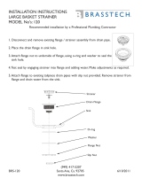
Figure 1 shows an explosion of the waste drain installation
10
Sink BowlSnap-in Strainer
Sink Flange
Gasket
Waste Drain
Assembly
Figure 1
1. Remove the Snap-in Strainer and unscrew the Sink Flange from the Waste Drain
Assembly. Apply a bead of Plumber’s Putty to the bottom of the Sink Flange where it
contacts the sink bowl.
2. Make sure the underside and inside mating surfaces of the sink bowl in the area of
the drain are clean.
3. Install the Waste Drain Assembly and Gasket from below the sink.
4. Install the Sink Flange thru the sink drain opening and screw it into the Waste Drain
Assembly below.
5. Before tightening, position the waste drain Handle to the desired location. Tighten
the Sink Flange securely with a Sink Flange Tool* or similar.
Sink Flange Tool
Figure 2
* Sink Flange Installation Tool # 017670-45
is available through T&S (see last page).
*

Figure 3
Outlet
Overflow Head
Overflow Tube
Coupling Nut
Seal
Overflow Port
Outlet Adapter
6. If Over ow* is used - Install the Over ow Head in the sink. Measure and cut the
over ow tube to t into the Over ow Head and Over ow Port on the waste drain
Outlet. Install the Coupling Nuts and Seals on the over ow tube. Install the over ow
tube and tighten the connections.
General Instructions
11
7. Connect the drain line to the waste drain Outlet. If Outlet Adapters are used, seal all
threaded connections with pipe sealant.
8. Open and close the waste drain several times to check the operation. Check for leaks.
Maintenance
Figure 4 shows a maintenance explosion of a typical Waste Drain Assembly.
Snap-in Strainer
Plunger O-ring
Plunger
Assembly
Handle
Handle Nut
Figure 4
Parts kit B-39K* is available for all servicable seals in Waste Drain models B-3940 Series
thru B-3970 Series. Most seal service and maintenance can be conducted without
removal of the waste drain from the sink or plumbing system. A typical maintenance
procedure is as follows:
1. Remove the Snap-in Strainer to allow access to the plunger.
2. Loosen and unscrew the Handle Nut and remove the Handle Assembly. Handle
Assembly seals can be serviced at this point.
3. Lift and remove the Plunger. The plunger O-Ring can be serviced at this point.
4. Re-assemble in reverse order. Check for leaks.
* Over ow B-3990-OF
is available through T&S
(see last page).
* B-39K is available through T&S (see last page).

RELATED T&S BRASS PRODUCT LINE
B-3999-OF
Waste Drain
Overflow Kit
017670-45
Waste Drain
Installation Tool
B-39K
Parts Kit for
Waste Drains
T&S BRASS AND BRONZE WORKS, INC.
A rm commitment to application-engineered plumbing products
2 Saddleback Cove, P.O. Box 1088 T & S Brass-Europe
Travelers Rest, SC 29690 ‘De Veenhoeve’
Phone: (864) 834-4102 Oude Nieuwveenseweg 84
Fax: (864) 834-3518 2441 CW Nieuwveen
E-mail: [email protected] The Netherlands
/