Page is loading ...

Date Issued: 05/10/16 IS-43925-USCB
We’re here to help 866-558-5706
Hrs: M-F 9am to 5pm EST
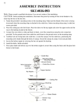
1) Pass fixture wire thru tube. Thread tube onto threaded
nipple on top of fixture and tighten to secure.
2) Pass fixture wire thru upper trim assembly. Thread upper
trim assembly onto of tube. Tighten to secure.
3) Thread small threaded nipple into end of large loop. Pass
fixture wire through threaded nipple and bottom of large
loop. Thread small threaded nipple with large loop into cou-
pling on top of upper trim assembly. Tighten to secure loop.
4) Thread small threaded nipple into end of small loop. Pass
threaded nipple on small loop up through hole in canopy.
Place lockwasher onto end of threaded nipple protruding
from inside canopy. Thread hexnut onto threaded nipple
protruding from inside canopy. Tighten to secure loop.
5) Attach one end of chain to large loop on top of fixture body.
Attach other end of chain to small loop on canopy.
6) Weave fixture wires and ground wire through chain links no
more than 3 inches apart.
7) Pass fixture wires through hole in small loop on canopy and
through hole in canopy.
8) Find the appropriate threaded holes on mounting strap. As-
semble mounting screws into threaded holes.
9) Attach mounting strap to outlet box. Mounting strap can be
adjusted to suit position of fixture.
10) Grounding instructions: (See Illus. A or B)
A) On fixtures where mounting strap is provided with a
hole and two raise dimples. Wrap ground wire from
outlet box around green ground screw, and thread into
hole.
B) On fixtures where a cupped washer is provided. Put
ground wire from outlet box under cupped washer
and green ground screw and thread screw into hole in
mounting strap.
If fixture is provided with ground wire. Connect fixture
ground wire to outlet box ground wire with wire connector,
after following the above steps. Never connect ground wire
to black or white power supply wires.
11) Make wire connections. Reference chart below for correct
connections and wire accordingly.
12) Push fixture to ceiling, carefully passing mounting screws
through holes in canopy. Make sure all wires are inside
canopy and do not get pinched between canopy and ceiling.
13) Thread lockup knobs onto mounting screw and tighten to
secure fixture to ceiling.
14) Insert recommended bulbs.
15) Thread hexnut onto threaded nipple leaving approximately
3/8-1/2 inch thread showing.
16) Using same end of threaded nipple, thread threaded nipple
into coupling just below sockets. Make sure threaded
nipple does not protrude pass opening in coupling.
17) Thread hexnut on threaded nipple up to coupling. Secure by
holding coupling and tighten hexnut with wrenches.
18) Thread hexnut on bottom of nipple leaving approximately
5/8-in threads showing.
19) Pass washer first and then rubber washer onto threaded
nipple.
20) Raise glass up passing threaded nipple thru hole in center of
glass. Check to determine when the glass touches the rub-
ber washer, the top of glass should be touching bottom of
fixture. It may be required to lower glass and adjust hexnut
up/down until you are able to bottom out on both rubber
washer and top of glass.
21) Once correct glass alignment is achieved, pass rubber
washer first and then washer onto threaded nipple. Thread
long hexnut onto threaded nipple. Tighten long hexnut to
secure glass. (DO NOT over tighten.)
22) Pass Trim (small hole) over threaded end of finial. Raise trim
and finial together and thread finial on end of long hexnut.
Tighten to secure. DO NOT over tighten.
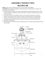
1) Remove coupling from upper trim assembly leaving the
small threaded nipple in place. See REF. 1.
2) Remove the pan from assembly and replace with canopy
(one with 2 additional small holes) with opening upward.
Pass small threaded nipple thru center hole in canopy. Pass
lockwasher over small threaded nipple. Thread hexnut onto
small threaded nipple and tighten to secure. See REF. 2.
3) Pass fixture wire thru tube. Thread tube over threaded
nipple protruding from above fixture. Tighten to secure.
4) Pass fixture wire thru upper trim and canopy assembly.
Thread upper trim and canopy assembly into tube. Tighten
to secure.
5) Continue with steps 12 - 22 in Chain Hung Mounting
instructions.
CAUTION – RISK OF SHOCK – Disconnect Power at the main
circuit breaker panel or main fuse box before starting and during
the installation.
CHAIN HUNG MOUNT
GREEN GROUND
SCREW
CUPPED
WASHER
OUTLET BOX
GROUND
FIXTURE
GROUND
DIMPLES
WIRE CONNECTOR
OUTLET BOX
GROUND
GREEN GROUND
SCREW
FIXTURE
GROUND
A
B
Connect Black or
Red Supply Wire to:
Connect
White Supply Wire to:
Black White
*Parallel cord (round & smooth) *Parallel cord (square & ridged)
Clear, Brown, Gold or Black
without tracer
Clear, Brown, Gold or Black
with tracer
Insulated wire (other than green)
with copper conductor
Insulated wire (other than green)
with silver conductor
*Note: When parallel wires (SPT I & SPT II)
are used. The neutral wire is square shaped
or ridged and the other wire will be round in
shape or smooth (see illus.)
Neutral Wire
SEMI FLUSH MOUNT
REF. 1
REF. 2
Remove
Add
COUPLING
LOCKWASHER
PAN
SMALL THREADED
NIPPLE
UPPER TRIM
ASSEMBLY
HEXNUT
LOCKWASHER
CANOPY
SMALL THREADED
NIPPLE
UPPER TRIM
ASSEMBLY

Date Issued: 05/10/16 IS-43925-USCB
We’re here to help 866-558-5706
Hrs: M-F 9am to 5pm EST
OUTLET BOX
WIRE
CONNECTORS
MOUNTING
STRAP
HEXNUT
STRAP
MOUNTING SCREWS
MOUNTING SCREW(S)
LOCKWASHER(S)
LOCK-UP KNOB(S)
SMALL THREADED NIPPLE
SMALL
LOOP
CHAIN
LARGE
LOOP
SMALL THREADED NIPPLE
COUPLING
UPPER TRIM
ASSEMBLY
TUBE
FIXTURE
BULB
(NOT INCLUDED)
COUPLING
HEXNUT
THREADED NIPPLE
HEXNUT
WASHER
RUBBER WASHER
RUBBER WASHER
WASHER
LONG HEXNUT
TRIM
FINIAL

CAJA DE SALIDA
CONECTORES
DE CABLES
MOUNTING
STRAP
TUERCA
HEXAGONAL
TORNILLOS DE
MONTAJE DE LA CORREA
TORNILLOS DE MONTAJE
ARANDELA
DE SEGURIDAD(S)
PERILLA DE BLOQUEO(S)
NIPLE ROSCADO PEQUEÑO
LAZO
PEQUEÑO
CADENA
LAZO
GRANDE
NIPLE ROSCADO PEQUEÑO
DE ACOPLAMIENTO
CONJUNTO AJUSTE
SUPERIOR
TUBO
ARTIFACTO
BOMBILLA
(NOT INCLUDIA)
DE ACOPLAMIENTO
TUERCA
HEXAGONAL
THREADED NIPPLE
HEXNUT
ARANDELA
ARANDELA
DE GOMA
ARANDELA
DE GOMA
TUERCA
HEXAGONAL LARGA
ARANDELA
RECORTAR
CAPUCHÓN

Date Issued: 05/10/16 IS-43925-CB
INSTRUCTIONS
For Assembling and Installing Fixtures in Canada
Pour L’assemblage et L’installation Au Canada
Nous sommes là pour vous aider 866-558-5706
Heures : du lundi au vendredi, de 9h à 17h (heure de l’Est)
BOÎTE Â PRISES
CONNECTORS
DE FIL
ÉTRIER
DE MONTAGE
ECROU
HEXAGONAL
VIS DE SUPPORT
DE SANGLE
VIS DE MONTAGE(S)
RONDELLE
DE BLOCAGE(S)
BOULE DE BLOCAGE(S)
PETIT RACCORD FILETÉ
PETITE
BOUCLE
CHAÎNE
GRANDE
BOUCLE
PETIT RACCORD FILETÉ
ACCOUPLEMENT
ENSEMBLE
GARNITURE
SUPÉRIEUR
TUBE
LUMINAIRE
AMPOULE
(PAS INCLUSE)
ACCOUPLEMENT
ECROU HEXAGONAL
RACCORD À VIS
ECROU HEXAGONAL
RONDELLE
RONDELLE
EN CAOUTCHOUC
RONDELLE
EN CAOUTCHOUC
RONDELLE
ÉCROU
HEXAGONAL LONG
TRIM
ORNAMENT
/


