Honeywell MS9520/40 Voyager User manual
- Category
- Bar code readers
- Type
- User manual

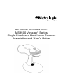
METROLOGIC INSTRUMENTS, INC.
MS9500 Voyager
®
Series
Single-Line Hand Held Laser Scanner
Installation and User's Guide

Copyright
© 2008 by Metrologic Instruments, Inc. All rights reserved. No part of this
work may be reproduced, transmitted, or stored in any form or by any means
without prior written consent, except by reviewer, who may quote brief
passages in a review, or provided for in the Copyright Act of 1976.
Trademarks
Metrologic is a registered trademark of Metrologic Instruments, Inc.
Products identified in this document are hereby acknowledged as
trademarks, registered or otherwise, of Metrologic Instruments, Inc. or their
respective companies.

ii
T
ABLE OF
C
ONTENTS
Introduction
Product Overview ............................................................................................. 1
Scanner and Accessories................................................................................. 2
Scanner Components....................................................................................... 4
The PowerLink Cable
Disconnecting............................................................................................... 5
Connecting ................................................................................................... 5
Labels............................................................................................................... 6
Maintenance..................................................................................................... 6
Installing the Scanner to the Host System
RS232, Laser Emulation, and Light Pen Emulation.......................................... 7
RS485 .............................................................................................................. 8
Keyboard Wedge.............................................................................................. 9
Stand-Alone Keyboard ................................................................................... 10
Integrated USB
Full Speed .................................................................................................. 11
Low Speed ................................................................................................. 11
The MS9540 VoyagerCG
®
Series
How to Use CodeGate
®
and the Manual Activation Mode.............................. 12
Three Modes of Operation.............................................................................. 12
Stand Kits
Types.............................................................................................................. 13
Assembly........................................................................................................ 14
Indicators
Audible ........................................................................................................... 17
Visual ............................................................................................................. 18
Failure Modes................................................................................................. 19
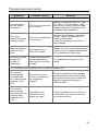
Configuration Modes .......................................................................................... 20
Upgrading the Firmware..................................................................................... 23
Depth of Field ..................................................................................................... 24

ii
T
ABLE OF
C
ONTENTS
IR Activation Range............................................................................................ 25
Applications and Protocols ................................................................................. 26
Troubleshooting Guide ....................................................................................... 27
RS232 Demonstration Program ......................................................................... 30
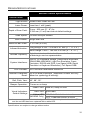
Design Specifications
Operational..................................................................................................... 31
Mechanical ..................................................................................................... 32
Electrical......................................................................................................... 32
Environmental ................................................................................................ 32
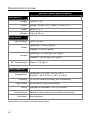
Default Settings .................................................................................................. 33
Scanner and Cable Terminations
Scanner Pinout Connections.......................................................................... 38
Cable Connector Configurations .................................................................... 40
Limited Warranty ................................................................................................ 42
Regulatory Compliance
Safety ............................................................................................................. 43
EMC ............................................................................................................... 44
Patents ............................................................................................................... 46
Index .................................................................................................................. 47
Contact Information and Office Locations........................................................... 49

1
I
NTRODUCTION
Product Overview
Metrologic's MS9500 Voyager
®
series of hand-held (single-line) laser scanners
offers the user an aggressive solution for scanning all standard 1D bar codes
including GS1 DataBar™ (RSS) bar codes. The MS9500 series is equipped with
both in-stand and out-of-stand operation enabling hand-held or fixed projection
scanning. The MS9520 Voyager model includes all of the same features as the
MS9540 VoyagerCG model, with the exception of Metrologic’s patented
CodeGate
®
technology.
The MS9540, VoyagerCG incorporates Metrologic’s patented auto-trigger and
CodeGate button feature. When a bar code is place in the scanner’s IR range,
the auto-trigger activates the laser enabling the user to align the visible laser line
over the bar code selected for scanning. The user can then press the CodeGate
button, to transmit the data to the host system. When the MS9540 is placed in
the stand the CodeGate button feature will automatically deactivating for hands
free operation.
Some additional key product features for the MS9500 series include:
• Auto-trigger operation and auto-stand detect
• CodeGate data transmission technology (MS9540 only)
• Flash – upgradeable firmware
• Easy configuration with MetroSelect
®
bar codes and MetroSet
®
2
Windows
®
compatible software
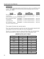
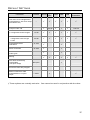
• Support for common interfaces including USB (see chart below)
V
OYAGER
V
OYAGER
CG I
NTERFACE
MS9520 – 00 MS9540 – 00 Laser Emulation RS232 Transmit/Receive
MS9520 – 11 MS9540 – 11
RS485
, RS232 (TXD, RXD, RTS, CTS)
MS9520 – 14 MS9540 – 14 RS232 (TXD, RXD, RTS, CTS, DTR, DSR)
MS9520 – 38 MS9540 – 38 Low Speed USB*, RS232 (TXD, RXD, RTS, CTS)
MS9520 – 40 MS9540 – 40 Full Speed USB, RS232 (TXD, RXD, RTS, CTS)
MS9520 – 41 MS9540 – 41 RS232/Light Pen Emulation
MS9520 – 47 MS9540 – 47
Keyboard Wedge, Stand-Alone Keyboard and
RS232 Transmit/Receive
* Configurable for Keyboard Emulation Mode or Serial Emulation Mode. The default
setting is Keyboard Emulation Mode.
Applicable for IBM
®
host applications.

2
I
NTRODUCTION
Scanner and Accessories
B
ASIC
K
IT
Part # Description
MS9520
or
MS9540
Voyager Bar Code Scanner
or
VoyagerCG Bar Code Scanner with CodeGate
00-02544 MetroSelect Single-Line Configuration Guide*
00-02410
MS9500 Voyager Series Single-Line Hand Held Laser
Scanner Installation and User’s Guide*
*
Available for download on the Metrologic website - www.metrologic.com
O
PTIONAL
A
CCESSORIES
Part # Description
AC to DC Power Transformer - Regulated 5.2VDC @ 1A output.
46-00525 90VAC to 255VAC, United States, Canada and Japan
46-00526 90VAC to 255VAC, Continental European
46-00527 90VAC to 255VAC, United Kingdom
46-00528 90VAC to 255VAC, Australia
46-00529 90VAC to 255VAC, China
53-53000x-3
RS232 PowerLink Cable with Built in Power Jack
Black, Coiled Cord, with Long Strain Relief
59-59000x-3
RS232 PowerLink Cable with Built in Power Jack
Black, Straight cord, with Short Strain Relief
53-53002x-3
Keyboard Wedge PowerLink Cable with Adapter Cable
Black, Coiled cord, with Long Strain Relief
53-53020x-3
Stand Alone Keyboard Wedge PowerLink Cable
Black, Coiled cord, with Long Strain Relief
Other items may be ordered for the specific protocol being used. To order additional items,
contact the dealer, distributor or call Metrologic’s Customer Service Department at
1-800-ID-METRO or 1-800-436-3876.

3
I
NTRODUCTION
Scanner and Accessories
O
PTIONAL
A
CCESSORIES
Part # Description
53-53213x-N-3
USB Full Speed Cable Locking Plus-Power™ Type A,
Black, Coiled Cord with Long Strain Relief
53-53214x-N-3
USB Full Speed Cable Locking Plus-Power™ Type A,
Black, Coiled Cord with Long Strain Relief, Extended
Length
Not for use with Low Speed USB scanners.
Use with Full Speed USB scanners only.
53-53235x-N-3
USB Low Speed Communication Cable, Type A
Black, Coiled Cord with Long Strain Relief
MVC**
RS485
Metrologic Voltage Converter Cable
±12VDC to +5.2VDC
** Contact a Metrologic customer service representative for additional
information on the MVC converter cable series and the host connections
available.
46-46128 Free-Standing Stand with Accessories
46-46351 Hard Mount Accessory Kit (used with kit #46-46128)
46-46508 Wall Mount Hanger Accessory Kit
Other items may be ordered for the specific protocol being used. To order additional items,
contact the dealer, distributor or call Metrologic’s Customer Service Department at
1-800-ID-METRO or 1-800-436-3876.
Applicable for IBM
®
host applications.

4
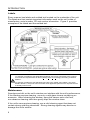
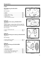
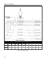
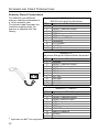
INTRODUCTION
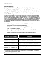
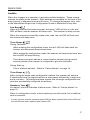
Scanner Components
No. Item Description
1
Green LED
♦
See Visual Indicators on page 18
2
Red LED
♦
See Visual Indicators on page 18
3
Yellow LED
♦♦
See Visual Indicators on page 18
4
Button
♦♦
See How to use CodeGate on page 12
5 Red Window Laser Aperture
6 Speaker See Audible Indicators on page 17
7 Cable Release Pin-Hole See The PowerLink Cable on page 5
8 Cable Connection
10-pin RJ45, Female Socket,
See Scanner Pinout Connections on page 38
Figure 1. Scanner Components
♦
In some custom units the standard green LED has been replaced with a
blue LED and the red LED has been replaced with a white LED.
♦♦
Items are provided with the MS9540, VoyagerCG model only.

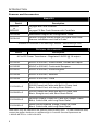
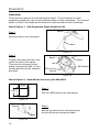
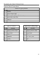
5
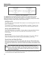
I
NTRODUCTION
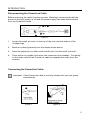
Disconnecting the PowerLink Cable
Before removing the cable from the scanner, Metrologic recommends that the
power on the host system is off and the power supply has been disconnected
from the PowerLink cable.
Figure 2.
1. Locate the small ‘pin-hole’ on the top of the unit near the bottom of the
Voyager logo.
2. Bend an ordinary paperclip into the shape shown above.
3. Insert the paperclip (or other small metallic pin) into the small ‘pin-hole’.
4. There will be an audible click when the connector lock releases. Pull gently
on the strain-relief of the PowerLink cable to separate the cable from the
scanner.
Connecting the PowerLink Cable
Important: If the PowerLink cable is not fully latched, the unit can power
intermittently.
Figure 3.
Figure 4.

6
I
NTRODUCTION
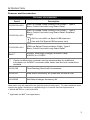
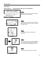
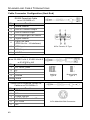
Labels
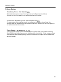
Every scanner has labels and molded text located on the underside of the unit.
The labels and text contain important information such as the unit’s date of
manufacture, serial number, CE and caution information. Figure 5 provides
examples of the labels and the molded text.
Figure 5 . Molded Text and Label Examples
Caution:
To maintain compliance with applicable standards, all circuits connected to the scanner
must meet the requirements for SELV (Safety Extra Low Voltage) according to EN/IEC
60950-1.
To maintain compliance with standard CSA-C22.2 No. 60950-1/UL 60950-1 and norm
EN/IEC 60950-1, the power source should meet applicable performance requirements for
a limited power source.
Maintenance
Smudges and dirt on the unit's window can interfere with the unit's performance.
If the window requires cleaning, use only a mild glass cleaner containing no
ammonia. When cleaning the window, spray the cleaner onto a lint free,
non-abrasive cleaning cloth then gently wipe the window clean.
If the unit's case requires cleaning, use a mild cleaning agent that does not
contain strong oxidizing chemicals. Strong cleaning agents may discolor or
damage the unit's exterior.

7
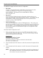
I
NSTALLING THE
S
CANNER TO THE
H
OST
S
YSTEM
RS232, Laser Emulation, and Light Pen Emulation
1. Turn off the host system.
2. Connect the 10-pin RJ45 male
connector into the jack on the
scanner. There will be an audible
click when the connector lock
engages.
If the scanner is receiving
power from the host system,
skip to step #5.
3. Connect the L-shaped plug of the
power supply into the power jack
on the PowerLink cable.
4. Verify the AC input requirements of
the power supply match the AC
outlet. Connect the power supply
into an AC outlet. The outlet should
be near the equipment and easily
accessible.
5. Connect the PowerLink cable to
the proper port on the host system.
6. Turn on the host system.
Plugging the scanner into a port on the host system does not guarantee
that scanned information will be communicated properly to the host
system. Please refer to the MetroSelect Single-Line Configuration
Guide or MetroSet2’s help files for instructions on changing the
scanner’s factory default configuration. The scanner and host system
must use the same communication protocols.
All MS95x0-00 scanners leave the factory with the Laser Emulation
Mode enabled. If you recall defaults while re-configuring your scanner
the Laser Emulation Mode will no longer be enabled. Refer to the
MS95
x
0-00 Laser Emulation Mode section of the MetroSelect Single-
Line Configuration Guide for information on enabling the Laser
Emulation Mode.
See caution on page 6
.
Figure 6.

8
I
NSTALLING THE
S
CANNER TO THE
H
OST
S
YSTEM
RS485
1. Turn off the host system.
2. Plug the male 10-pin RJ45 end of the
MVC cable into the 10-pin socket on
the scanner. You will hear a ‘click’
when the connection is made.
3. Connect the other end of the MVC
cable to the host device.
4. Turn on the host system.
Plugging the scanner into a port on the host system does not guarantee
that scanned information will be communicated properly to the host
system. Please refer to the MetroSelect Single-Line Configuration
Guide or MetroSet2’s help files for instructions on changing the
scanner’s factory default configuration. The scanner and host system
must use the same communication protocols.
See caution on page 6.
Applicable for IBM
®
host applications.
Figure 7.

9
I
NSTALLING THE
S
CANNER TO THE
H
OST
S
YSTEM
Keyboard Wedge
1. Turn off the host system.
2. Connect the 10-pin RJ45 male
connector into the jack on the scanner.
You will hear a ‘click’ when the
connection is made.
If the scanner is receiving
power from the host system,
skip to step #5.
3. Connect the L-shaped plug of the
power supply into the power jack on
the PowerLink cable.
4. Verify the AC input requirements
of the power supply match the AC
outlet. Connect the power supply into
an AC outlet. The outlet should be near
the equipment and easily accessible.
5. Disconnect the keyboard from the PC.
6. Connect the PowerLink cable to the
keyboard and the PC’s keyboard port.
If necessary use the supplied adapter
cable (5-pin male DIN to 6-pin female
mini DIN adapter).
7. Power up the host system.
Plugging the scanner into a port on the host system does not guarantee that
scanned information will be communicated properly to the host system. Please
refer to the MetroSelect Single-Line Configuration Guide or MetroSet2’s help files
for instructions on changing the scanner’s factory default configuration.
The scanner and host system must use the same communication protocols.
Powering the MS95x0-47 directly from the computer can sometimes cause
interference with the operation of the scanner or the computer. Not all computers
supply the same current through the keyboard port, explaining why a scanner
may work on one computer and not another. Contact a Metrologic Customer
Service Representative if you require an external power supply.
See caution on page 6.
Figure 8.

10
I
NSTALLING THE
S
CANNER TO THE
H
OST
S
YSTEM
Stand-Alone Keyboard
1. Turn off the host system.
2. Connect the 10-pin RJ45 male
connector into the jack on the
scanner. You will hear a ‘click’
when the connection is made.
If the scanner is receiving
power from the host system,
skip to step #5.
3. Connect the L-shaped plug of the
power supply into the power jack
on the PowerLink cable.
4. Verify the AC input requirements
of the power supply match the AC
outlet. Connect the power supply
into an AC outlet. The outlet
should be near the equipment and
easily accessible.
5. Connect the PowerLink cable
to the keyboard port on the host
system.
6. Turn on the host system.
Powering the MS95x0-47 directly from the computer can sometimes cause
interference with the operation of the scanner or the computer. Not all computers
supply the same current through the keyboard port, explaining why a scanner
would work on one computer and not another. Contact a Metrologic Customer
Service Representative if you require an external power supply.
Plugging the scanner into a port on the host system does not guarantee that
scanned information will be communicated properly to the host system. Please
refer to the MetroSelect Single-Line Configuration Guide or MetroSet2’s help files
for instructions on changing the scanner’s factory default configuration.
The scanner and host system must use the same communication protocols.
See caution on page 6.
Figure 9.

11
Figure 10.
I
NSTALLING THE
S
CANNER TO THE
H
OST
S
YSTEM
Integrated USB: Full Speed (-40)
Low Speed (-38)
1. Turn off the host system.
2. Connect the 10-pin RJ45 male
connector of the USB cable into the
jack on the scanner. You will hear a
‘click’ when the connection is made.
3. Connect the other end of the USB
cable to the host USB port.
4. Turn on the host system.
As a default, the MS95x0-38 leaves the factory with USB Keyboard
Emulation Mode enabled.
For information on configuring the MS95x0-38 for USB Serial
Emulation Mode, please refer to the USB section of the MetroSelect
Single-Line Configuration Guide (
MLPN
00-02544).
Plugging the scanner into a port on the host system does not guarantee
that scanned information will be communicated properly to the host
system. Please refer to the MetroSelect Single-Line Configuration
Guide or MetroSet2’s help files for instructions on changing the
scanner’s factory default configuration. The scanner and host system
must use the same communication protocols.
See caution on page 6.

12
T
HE
MS9540
V
OYAGER
CG
®
S
ERIES
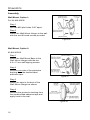
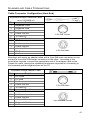
How to Use CodeGate and the Manual Activation Mode
C
ODE
G
ATE
®
M
ANUAL
A
CTIVATION
M
ODE
*
*
This feature is not a default setting.
Refer to the MetroSelect Configuration
Guide for instructions on enabling the
Manual Activation Mode.
Figure 11.
Figure 12.
Three Modes of Operation
Auto Trigger, In-Stand
• Auto-triggers while in the stand
• Bar code is automatically decoded and transmitted
CodeGate, Out-of-Stand
• CodeGate activates when removed from the stand
• Bar code data is transmitted when the button is pressed
Manual Activation Mode*, Out-of-Stand
• Button activates laser
• Bar code data is scanned and transmitted while button is held down

13
S
TAND
K
ITS
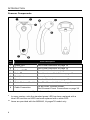
Types
Free Standing Kit #46-46128
(Figure 13)
Kit Contains:
a. Stand........................................................... Qty. 1
b. Apron........................................................... Qty. 1
c. Screw, M3 x 6 mm ...................................... Qty. 2
d. Washer, #5 x .5 OD..................................... Qty. 2
e. Stand Anchor .............................................. Qty. 1
f. M3 x 20 mm Set Screw ............................... Qty. 1
Optional
Hard Mount Accessory Kit #46-46351
(Figure 14)
This kit, used in conjunction with the stand kit
(#46-46128), can be used to hard mount (bolt)
the MS9500 to the countertop.
Kit Contains:
a. Screw, #8 Round Head .............................. Qty. 4
b. Base ........................................................... Qty. 1
Optional
Wall Mount Hanger Accessory Kit #46-46433
(Figure 15)
Kit Contains:
a. Screw #8 Round Head ................................ Qty. 2
b. Wall Mount Hanger ..................................... Qty. 1
Optional
Wall Mount Hanger Kit #46-46508
(Figure 16)
Kit Contains:
a.
Wall Mount Hanger ..................................... Qty. 1
b. Wall Mount Base ........................................ Qty. 1
c. 4.8 x 13 mm, Self Tapping Screw .............. Qty. 2
d. Double-Sided Adhesive Tape .................... Qty. 1
e. #8 Wood Screw.......................................... Qty. 2
e
.
d
.
a
.
b
.
f.
c.
Figure 13.
a
.
b
.
Figure 14.
Figure 15.
Figure 16.

14
S
TAND
K
ITS
Assembly
There are two options for assembling the stand. The first option is a self-
supporting stand that can be moved freely about on the countertop. The second
option is used if the stand will be bolted or hard-mounted to the countertop.
Stand Option 1: Self-Supported Stand Kit #46-46128
Step 1
Slide the apron over the stand.
Figure 17.
Step 2
Position the stand so that it sits
under the tab on the apron.
Then secure the apron to the
stand using the two M3 x 6 mm
screws and the two #5 washers
provided.
Figure 18.
Stand Option 2: Hard-Mount Accessory Kit #46-46351
Step 1
Drill four #39 holes in the countertop.
Figure 19.
Step 2
Secure the base to the countertop with
the four #8 wood screws provided.
Figure 20.
Stand
A
p
ron
A
pron
Stand
M3 x 6 mm
Scre
w
#5 Washer
Tab
Base
#8 Wood
Screw
2.00
2.00

15
S
TAND
K
ITS
Assembly
Stand Option 2: Hard-Mount Kits #46-46128 and #46-46351
Step 3
Screw the stand anchor onto the base
assembly until it sits flush.
Step 4
Remove the logo plate on the stand by
gently using an exacto knife to release
the plate hook.
Step 5
Position the stand over the base
assembly.
Step 6
Secure the stand to the base assembly
by installing and tightening the M3 set
screw under the logo plate as shown.
Step 7
Snap the logo plate back into place.
Anchor from
Kit #46-46128
Base Assembly from
Kit #46-46351 o
r
MS951 Stand Base
Figure 21.
Figure 22.
Figure 23.
Figure 24.
Figure 25.

16
S
TAND
K
ITS
Assembly
Wall Mount, Option 1:
For Kit #46-46508
Step 1
Drill two #39 pilot holes 3.00″ apart.
Step 2
Attach the Wall Mount Hanger to the wall
with the two #8 wood screws provided.
Wall Mount, Option 2:
Kit #46-46508
Step 1
Attach the Wall Mount Base to the
Wall Mount Hanger with the two
4.8 x 13 mm self-tapping screws.
Step 2
Remove one side of the protective
backing from the double-sided
adhesive tape.
Step 3
Attach the tape to the back of the
Wall Mount Hanger as shown.
Step 4
Remove the protective backing from
the double-sided adhesive tape and
apply hook to the wall.
Figure 26.
Figure 27.
Figure 28.
Page is loading ...
Page is loading ...
Page is loading ...
Page is loading ...
Page is loading ...
Page is loading ...
Page is loading ...
Page is loading ...
Page is loading ...
Page is loading ...
Page is loading ...
Page is loading ...
Page is loading ...
Page is loading ...
Page is loading ...
Page is loading ...
Page is loading ...
Page is loading ...
Page is loading ...
Page is loading ...
Page is loading ...
Page is loading ...
Page is loading ...
Page is loading ...
Page is loading ...
Page is loading ...
Page is loading ...
Page is loading ...
Page is loading ...
Page is loading ...
Page is loading ...
Page is loading ...
Page is loading ...
Page is loading ...
Page is loading ...
Page is loading ...
-
 1
1
-
 2
2
-
 3
3
-
 4
4
-
 5
5
-
 6
6
-
 7
7
-
 8
8
-
 9
9
-
 10
10
-
 11
11
-
 12
12
-
 13
13
-
 14
14
-
 15
15
-
 16
16
-
 17
17
-
 18
18
-
 19
19
-
 20
20
-
 21
21
-
 22
22
-
 23
23
-
 24
24
-
 25
25
-
 26
26
-
 27
27
-
 28
28
-
 29
29
-
 30
30
-
 31
31
-
 32
32
-
 33
33
-
 34
34
-
 35
35
-
 36
36
-
 37
37
-
 38
38
-
 39
39
-
 40
40
-
 41
41
-
 42
42
-
 43
43
-
 44
44
-
 45
45
-
 46
46
-
 47
47
-
 48
48
-
 49
49
-
 50
50
-
 51
51
-
 52
52
-
 53
53
-
 54
54
-
 55
55
-
 56
56


Honeywell MS9520/40 Voyager User manual
- Category
- Bar code readers
- Type
- User manual
Ask a question and I''ll find the answer in the document
Finding information in a document is now easier with AI
Related papers
-
Honeywell MS9520 Voyager User manual
-
Metrologic MS9500 User manual
-
-
Metrologic Orbit MS7120-38 User manual
-
Honeywell MS7120 User manual
-
-
-
-
Metrologic Orbit MS7120 User guide
-
Honeywell AP-010-BT User manual
Other documents
-
-
-
-
-
-
-
-
 T'nB KPASBW Datasheet
-
-
Metrologic Eclipse MS5145-14 User manual
