
ENGLISH
ESPAÑOL FRANÇAIS
INS129A
®
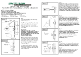
Available with and without stops.
Connections are either 1/2" I.P.S. pipe, 1/2"
copper sweat connections, 1/2" CPVC
connections or 1/2" PEX connections. If a
tub spout is installed, the drop and lookout
must be 1/2" copper or 1/2" IPS pipe.
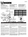
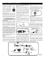
Measurements
The front face of the plaster ground is a
reference point for a nominal 5/8” thick
finished wall with the supply piping centerline
nominal 1 11/16” from the face of the stud.
Maximum wall thickness can only be obtained
with minimum distances from face of stud to
centerline of piping. For finished walls thicker
than illustrated, use handle extension kit
96945 for wall thickness 1 7/8” to 2 7/8”. Use
handle kit 96955 for wall thickness 2 7/8” to 3 7/8”.
CAUTION: Always turn water off before
disassembling the valve. Open valve
handle to relieve water pressure and to
insure that complete water shut-off has
been accomplished.
Disponible con y sin topes. Las conexiones son de
tubo I.P.S. de 1/2 pulgada (12,7 mm), conexiones de
cobre soldado de 1/2 pulgada (12,7 mm), conexiones
CPVC de 1/2 pulgada (12,7 mm) o conexiones PEX
de 1/2 pulgada (12,7 mm). Si se instala un Surtidor
Deslizable de Moen, la bajada y el niple a la vista
deben ser de cobre de 1/2 pulgada (12,7 mm) o de
tubería IPS de 1/2 pulgada (12,7 mm).
Medidas
La cara anterior de la plantilla de yeso es un punto de
referencia para un espesor nominal de la pared
acabada de 5/8" (15,8 mm) con la línea central de la
tubería de alimentación a una distancia nominal de 1
11/16" (42,8 mm) de la cara del tirante. El espesor
máximo de la pared sólo se puede lograr con distancias
mínimas entre la cara del tirante y la línea central de la
tubería. Para paredes acabadas más gruesas que las
ilustradas, use el juego de extensión del maneral 96945
para paredes de 1 7/8" (47,6 mm) a 2 7/8" (73 mm). Use
el juego de maneral 96955 para paredes con espesor
de 2 7/8" (73 mm) a 3 7/8" (98,4 mm).
ADVERTENCIA: Desconecte siempre el agua antes
de desarmar la válvula. Abra el maneral de la válvula
para desahogar la presión del agua y asegurarse de
que se ha logrado un corte completo de la misma.
Offert avec ou sans limiteur de température. Les
raccords sont des tuyaux IPS, des raccords de
ressuage en cuivre, des raccords CPVC ou des
raccords PEX de 13 mm. Si on installe un bec de
baignoire, la colonne descendante et le mamelon
doivent être des tuyaux en cuivre ou IPS de 13 mm.
Dimensions
Le devant de l’arrêt d’enduit est un point de
référence pour un mur fini d’une épaisseur suggérée
de 16 mm et un axe de tuyau d’alimentation d’une
valeur nominale de 26,3 mm po à partir du devant
du poteau. L’épaisseur murale maximale ne peut
être obtenue que si la distance entre le devant du
poteau et l’axe du tuyau est minimale. Pour les murs
finis plus épais que celui illustré : utiliser la trousse
d’extension de poignée 96945 pour un mur de
48 mm à 2 7/8 po d’épaisseur; la trousse de poignée
96955 pour un mur de 73 mm po à 3 7/8 : 98mm po
d’épaisseur.
ATTENTION : Toujours couper l’alimentation
en eau avant de démonter le robinet. Ouvrir le
robinet pour éliminer la pression d’eau et
s’assurer que l’alimentation a bien été
fermée
.
POSITEMP TUB
AND SHOWER VALVES
T180, TL180, 2350, 2360, L82300, 82350,
82340, L2300, 62300 Series
These instructions must be left with the homeowner
VÁLVULAS POSITEMP PARA
TINA Y REGADERA
Serie T180, TL180, 2350, 2360, L82300,
82350, 82340, L2300, 62300
Estas instrucciones deben permanecer con el propietario de la casa
SOUPAPES POSI-TEMP POUR
DOUCHE ET BAIGNOIRE
Séries T180, TL180, 2350, 2360, L82300,
82350, 82340, L2300, 62300
Ces directives doivent être remises au propriétaire.
WALL LINE
L NEA DE LA PARED
Ligne murale
FACE OF STUD
CARA DEL TIRANTE
Face du poteau
5/8" (16mm) Nominal Shown
5/8 (16mm) Nominal Ilustrado
16 mm, valeur nom. illustr e
2" (51mm) CC & PEX
1 7/8" (48mm) IPS & CPVC MAX
Wall/Mur max.
1-1/16" (26mm) MAX
(26 mm)
11" (279mm) MAX
ESCUTCHEON
CHAPET N
Rosace
4 1/2" (114mm)
PLASTER GROUND
EMPLASTE A TIERRA
Arr t d’enduit
KEY STOP
TOPE DE LA LLAVE
But e de cl
STOP TUBE
TUBO DE TOPE
Tube d’arr t
WASHER
ARANDELA
Rondelle
KNOB
ASSEMBLIES
CONJUNTOS DE PERILLAS
Assemblage de bouton
6’6"
(1981 mm)
FLOOR
Piso
Plancher
TUB SPOUT
SURTIDOR DE LA TINA
Bec de baignoire
3-1
/
2-1
Diam. d
e
D
WA
DI METRO
E
N
SHOWER 45" (1143mm) to 48" (1219mm) 32" (813mm)
REGADERA DE 45" (1143mm) A 48" (1219mm) (813m
m
32" (813mm)
FOR TUB/SHOWER COMBINATIONS AND TUB MODELS ONL
Y
32" (813mm) PARA COMBINACIONES DE TINA/REGADERA
Y MODELOS DE TINA SOLAMENTE
Douche de 1 143 1 219 mm
813 mm pour mod les avec combinaison
douche/baignoire et pour bains seulement
TEMPERATURE
LIMIT STOP
TOPE DEL LŒMITE
DE TEMPERATURA
Limiteur de temp rature
1-11/16" (17mm) Nominal Shown
(valeur nom. illustr.)
1/2" (13mm) MIN. CC & PEX
5/8" (16mm) MIN. IPS & CPVC
ENGLISH
ESPAÑOL
FRANÇAIS
1
Knob Cap
Tapa De Perilla
Capuchon du bouton
2
Knob Screw
Tornillo De Perilla
Vis du bouton
3
Knob Handle
Maneral De Perilla
Poignée à bouton
4
Lever Handle Hub
Cubo De Maneral De Palanca
Emboîtement de poignée à manette
5
Plug Button
Botón De Inserción
Bouton de bouchage
6
Lever handle insert (not furnished)
Pieza De Inserción Del Maneral De Palanca
(No Provisto)
Moyeu de poignée à manette (non fournie)
7
Lever Handle
Maneral De Palanca
Levier
8
Handle Adapter
Adaptador Del Maneral
Adapateur de poignée
9
Cap Screw
Tornillo De La Tapa
Vis de capuchon
10
Handle Screw
Tornillo Del Maneral
Vis de poignée
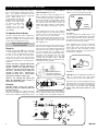
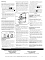
FLOOR
Piso
Plancher
1-1/16"
(27mm)
L
C
1 1/2"
(38mm)
3/16" (5mm)(typ)
PLASTER GROUND
PLANTILLA DE YESO
Arr t d’enduit
3-1/2" (89mm) MAX.
2-1/4" (57mm) MIN.
Diam. de l’ouverture murale
DIAMETER
WALL OPENING
DI METRO DE LA ABERTURA
EN LA PARED
PLASTIC TUB/SHOWER SURROUND
CERCO PL STICO TINA/REGADERA
Entourage de douche/baignoire en plastique
m
) 32" (813mm)
1
9mm) (813mm)
B
MODELS ONLY
N
A/REGADERA
E
NTE
m
i
naison
ulement
12
3
4
10
10
10
6
5
7
9
8
5
"The PEX fittings in the PEX valves (62360, 62380) have been third party
certified by CSA using the following: Nibco
®
and U.S. Brass QESTPEX
®
1/2"
Cu crimp rings and CSA certified 1/2" PEX tubing. Crimps were made using
Nibco
®
PEXlink
®
1/2" crimp tool in accordance with the Nibco
®
instructions."
"El organismo externo CSA certifica que los accesorios PEX en las válvulas PEX
(62360, 62380) utilizan los siguientes: anillos de pliegue de cobre Nibco ® y latón U.S.
QESTPEX ® de 1/2" (1,27 cm) y tubería PEX de 1/2" (1,27 cm) certificada por CSA.
Los anillos de pliegue fueron fabricados usando una herramienta de plegado Nibco ®
PEXlink ® de 1/2" (1,27 cm) de acuerdo a las instrucciones Nibco ®."
«Les raccords PEX de ces soupapes(62360, 62380) ont été homologués par une
tierce partie, la CSA, à l’aide des pièces suivantes: Anneaux de sertissage
en cuivre de 12,7 mm Nibco
®
et QESTPEX, laiton américain, de 12,7 mm et
tube PEX de 12,7 mm homologué par la CSA. Les sertissages ont été
effectués à l’aide d’un outil de sertissage de 12,7 mm PEXlink Nibco
®
selon
les directives de Nibco
®
.»

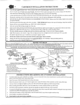
Before turning water on during either rough-in or
trim-out, ensure that the cartridge retainer clip is in
place. The cartridge and retainer clip were
properly installed and tested prior to leaving the
factory. While unlikely, it is
possible that due to handling the
retainer clip may not be properly
installed. If the retainer clip is
not properly installed, water
pressure could force the
cartridge out of the casing
causing personal injury and/or
water damage.
To Operate Shut-off Stops
This type is integral with casting, actuated by a
screwdriver, requiring a 90° turn to open or close.
When the screwdriver slot is vertical the stop is
closed; when horizontal the stop is open.
MAKE SURE ALL WATER
SUPPLIES ARE OFF.
Rough-In
Install the casting with the arrow pointing up
or the word “TOP” facing the ceiling. If the valve
is used for shower only, plug the bottom outlet. If
the valve is used for both a tub and shower,
connect the top outlet to the shower and the
bottom to the tub spout. Secure all pipes and the
shower ell and/or tub drop ell. Use Teflon tape on
all threads.
Caution: This valve is equipped with the Moen
long-life POSI-TEMP cartridge designed for
smooth, trouble free operation. When
soldering do not heat valve any higher than
necessary. Overheating may damage the
cartridge or rubber stops. Following this
direction will allow you to solder without
removing the cartridge or rubber stops.
Warning: The cartridge and rubber stops
MUST BE REMOVED before brazing or
resistance (electric) soldering.
Flushing
Important: Before closing wall openings,
pressure test valve and complete system using
flushing instructions.
Pipe chips, sand and other solids found in new
and renovated plumbing can damage the sealing
surfaces of the cartridge causing leakage or spool
blockage. To avoid damage, DO NOT TURN ON
SUPPLY VALVES until instructed.
Make sure both hot and cold supplies are off.
Rotate cartridge stem until the notch flat points up
to relieve pressure and insure complete shut-off.
Remove the cartridge (see Disassembly). Slowly
turn on both hot and cold supplies and flush out
the body and lines. Close the hot and cold
supplies and replace cartridge (see Reassembly).
Turn on both supplies and check the system for
leaks.
If the balancing spool becomes stuck, apparent
during the trim-out test, the valve will only deliver
a trickle of water or will only deliver hot or cold
water. If this occurs, proceed as follows:
Make sure that both hot and cold service lines are
ON and ensure that the integral stops are open
(stop models). The valve will not operate unless
both supplies are on.
If the valve still does not function properly, turn off
both hot and cold supplies and remove cartridge.
The inner spool in the cartridge should shake back
and forth freely. If this does not happen, remove
the stem assembly from the cartridge sleeve,
remove the cap from the assembly and remove
the balance spool. Carefully clean any foreign
material from the balance spool and stem
assembly and reassemble. Caution: DO NOT
DAMAGE O-RINGS. If the spool still does not free
up, replace the entire cartridge.
Make sure the o-rings are free of foreign material
and are lubricated. Reassemble stem assembly
into cartridge sleeve. Reassemble cartridge into
valve (see Reassembly). Turn on both water
supplies. The valve should function properly.
Slip-Fit spouts
C.C. SPOUT:
The Moen slip fit spout is designed with an o-ring
seal, specifically for installation with copper water
tube. Lookout must be free of burrs inside and out.
The edge must not be rolled. The outside surface
must be free from nicks and scratches.
Press and twist the spout onto the lookout upside
down. Tighten clamp screw with a 5/32” hex
wrench until it starts to bind. Correctly position
spout against the wall and tighten by hand.
Further tightening with pliers or hex wrench is not
needed. Do not overtighten.
IPS SPOUT:
CAUTION: This spout is ABS plastic and will crack
when in contact with some pipe thread
compounds. We recommend using Teflon Tape.
Screw tube spout onto pipe and tighten by hand.
If final turn by wrench is needed, use small wrench
with smooth jaws or pad wrench teeth with rag.
Pull outward to avoid scratching wall. DO NOT
INSERT TOOL INTO SPOUT END TO TURN
SPOUT.
INSTALLATION INSTRUCTIONS - ENGLISH
➤
➤
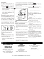
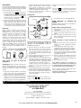
Clip
Cartridge
Ears
1
CLIP/BARS
ORIENT THE CLIP/BARS IN
THE SPOOL AND THE CAP
FINGERS AS SHOWN ABOVE
CAP
O-RINGS
BALANCE
SPOOL
CLIP/BARS
STEM ASSEMBLY
INS129A
CLAMP
SCREW
C.C
I.P.S.
RETAINER
CLIP
CARTRIDGE
NOTCH
WASHER
STOP TUBE
KEY STOP
TEMPERATURE
LIMIT STOP
KNOB
HANDLE
HANDLE
ADAPTER
CAP
SCREW
HANDLE
SCREW
HANDLE
SCREW
HANDLE
SCREW
KNOB
INSERT
PLUG BUTTON
PLUG BUTTON
HOT INLET
FORWARD
COLD INLET
TO REAR
INSTALL WITH
CARTRIDGE
STEM NOTCH
DOWN
TOP VIEWFRONT VIEW
LEVER
HANDLE
LEVER
HANDLE
TRADITIONAL
LEVER HANDLE
A
B
C
CAUTION: CARTRIDGE MUST BE INSTALLED
WITH HOT & COLD INLETS AS SHOWN
UP

Disassembly
Turn “OFF” hot and cold water supplies, then
rotate handle counterclockwise until the lever
points up to relieve pressure. Remove handle
parts.
1. For handle style A & B, remove handle insert or
plug button. Take out handle screw, remove
handle and washer. For handle style C,
remove cap screw and handle, then remove
handle screw and adapter
2. Remove temperature limit stop, key stop and
stop tube. Lift out retainer clip. Rotate cartridge
shell between the eleven and one o’clock
positions, grasp the cartridge stem with pliers
and pull out cartridge.
Reassembly
Orient cartridge, see illustration on previous page,
then re-insert cartridge by pushing it into the body
until the cartridge ears are flush and aligned with
the top and bottom of the valve body. Replace the
retainer clip with the legs straddling the cartridge
ears. Slide down into the bottom slot. This
prevents rotation and locks the cartridge into the
body. Reinstall stop tube and parts. Limit stop
must be installed with offset at TOP (12 o’clock)
position for maximum hot water. The notched flat
on the stem must point DOWN when mounting the
handle.
To Adjust Temperature Limit
Stops
CAUTION: Due to season temperature change of
the cold water supply, the temperature limit must
be readjusted accordingly to maintain the desired
maximum discharge temperature.
1. Rotate the handle counterclockwise to stop and
let water run till cold water is purged, check
temperature.
2. Rotate handle to off, remove handle parts (see
Disassembly) and temperature limit stop, rotate
clockwise to decrease and counterclockwise to
increase maximum hot water temperature,
reinstall temperature limit stop and handle (TIP:
Do not screw handle in until desired maximum
temperature is achieved)
3. Repeat steps until desired maximum
temperature is achieved.
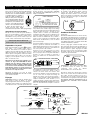
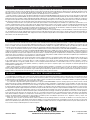
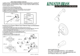
Trim
MAKE SURE ALL WATER SUPPLIES ARE OFF
TO INSTALL TRIM AFTER ROUGH-IN
1. Slide the flange into the long end of the shower
arm, wrap both ends of the shower arm with
teflon tape and screw long end into pipe ell
inside the wall. Do not install shower head at
this time.
2. Install tub spout (see spout installation
instructions).
3. Remove screw holding plaster ground and
stop tube guard in place and discard.
Temporarily install handle. Turn water on,
divert water to tub spout and flush the shower
riser for 15 seconds. Install shower head and
check for leaks. If there are no leaks, turn off
and remove handle and limit stop
4. Install escutcheon plate with 2 screws
provided. Mount with the escutcheon notch up.
5. Install temperature limit stops (see
Temperature Limit Stop section) ensure that
notched flat on the cartridge stem points
DOWN.
Handle Attachment :
For handle style A & B : Mount handle on stem
and replace handle screw tightly. Snap handle
insert or plug button in place.
For handle style C : Mount handle adapter on
stem and replace handle screw tightly. Mount
handle on adapter and replace set screw.
Not for use with Moentrol valves.
TO REMOVE STOP VALVE
Always turn water supply OFF before disassembly
(see Disassembly).
Removal of stop valve:
1. Remove handle parts (see Disassembly) and
escutcheon.
2. Using snap ring pliers, remove retaining ring
from valve body.
3. Grip stop valve stem with pliers and rotate
slightly to remove from valve body.
Re-Installation of new stop valve:
1. Check to be sure that stop valve stem is fully
seated in plug.
2. Insert stop valve until fully seated beyond
retaining ring groove in valve body.
3. Using snap ring pliers, place retaining ring in
valve body, making sure that ring is fully
seated.
4. Check orientation of stop valve for water flow.
(Stop is in the off position when screwdriver
slot is vertical).
5. Turn on water supply.
To Eliminate Cross-Piping On Back-
To-Back Installations, or To Correct
Reversed Rough-In Where Hot and
Cold Positions Are Reversed:
Remove cartridge assembly, rotate 180° and re-
install. (See Reassembly) Caution: Make sure
notch on stem is point up.
SHOWERHEAD
PIPE ELL
SHOWER ARM
NOTCH
CC
CONNECTIONS
ESCUTCHEON
TEMPERATURE
LIMIT STOP
ESCUTCHEON
SCREWS (2)
SPOUT
TUB LOOKOUT NIPPLE
2
KEY STOP
TEMPERATURE
LIMIT STOP
ROTATE LIMIT
STOP CLOCKWISE
TO REDUCE
FULL HOT POSITION
Call our toll free helpline number:
1 (800) 289-6636
1 (800) BUY-MOEN
For answers to any product, installation
replacement parts, or warranty questions.
Hours of operation are:
8:00 A.M. - 8 P.M. EST. Monday - Friday
8: A.M. - 6:30 P.M. EST. Saturday
Helpline
Visit our website at www.moen.com for more information
In Canada:
1-800-465-6130
Hours of operation are :
7:30 A.M. - 5:00 P.M. EST. Monday - Friday
Toronto:
1-905-829-3400
Hours of operation are :
7:30 A.M. - 5:00 P.M. EST. Monday - Friday
In Mexico:
(84) 88-08-26, 88-08-27,
o 91-800-84345
Hours of operation are :
8:00 A.M. - 8 P.M. EST. Monday - Friday
8: A.M. - 6:30 P.M. EST. Saturday
Page is loading ...
Page is loading ...
Page is loading ...
Page is loading ...

ENGLISH
ESPAÑOL
FRANÇAIS
INS129A MAY01
Moen, Incorporated 2001
Printed in U.S.A
Moen products have been manufactured under the highest standards of quality and workmanship. Moen warrants to the original consumer purchaser for as long as the original
consumer purchaser owns their home (the “Warranty Period” for homeowners), that this faucet will be leak and drip-free during normal use and all parts and finishes of this
faucet will be free from defects in material and manufacturing workmanship. All other purchasers (including purchasers for industrial, commercial and business use) are
warranted for a period of 5 years from the original date of purchase (the “Warranty Period” for non-homeowners).
If this faucet should ever develop a leak or drip during the Warranty Period, Moen will FREE OF CHARGE provide the parts necessary to put the faucet back in good working
condition and will replace FREE OF CHARGE, any part or finish that proves defective in material and manufacturing workmanship, under normal installation, use and service.
Replacement parts may be obtained by calling 1-800-289-6636 (Canada 1-800-465-6130), or by writing to the address shown. Proof of purchase (original sales receipt) from
the original consumer purchaser must accompany all warranty claims. Defects or damage caused by the use of other than genuine Moen parts are not covered by this warranty.
This warranty is applicable only to faucets purchased after December 1995 and shall be effective from the date of purchase as shown on purchaser’s receipt.
This warranty is extensive in that it covers replacement of all defective parts and finishes. However, damage due to installation error, product abuse, product misuse, or use
of cleaners containing abrasives, alcohol or other organic solvents, whether performed by a contractor, service company, or yourself, are excluded from this warranty. Moen will
not be responsible for labor charges and/or damage incurred in installation, repair or replacement, nor for any indirect, incidental or consequential damages, losses, injury or
costs of any nature relating to this faucet. Except as provided by law, this warranty is in lieu of and excludes all other warranties, conditions and guarantees, whether expressed
or implied, statutory or otherwise, including without restriction those of merchantability or of fitness for use.
Some states, provinces and nations do not allow the exclusion or limitation of incidental or consequential damages, so the above limitations or exclusions may not apply to
you. This warranty gives you specific legal rights and you may also have other rights which vary from state to state, province to province, nation to nation. Moen will advise you
of the procedure to follow in making warranty claims. Simply write to Moen Incorporated using the address below. Explain the defect and include proof of purchase and your
name, address, area code and telephone number.
Les produits Moen sont fabriqués selon les normes les plus élevées de qualité et de main-d’œuvre. Moen garantit à l'acheteur original, tant qu'il sera propriétaire de la maison
(la «période de garantie» des propriétaires), que ce robinet sera libre de toute fuite pendant son usage normal et qu'aucune pièce et qu'aucun fini de ce robinet ne présenteront
de défaut de matériel et de main-d’œuvre en usine. Tous les autres achats (y compris les achats à des fins industrielles, commerciales et d’affaires) sont garantis pendant cinq
(5) ans à compter de la date d’achat originale (période de garantie commerciale).
Si ce robinet fuit ou dégoutte durant la période de garantie, Moen s'engage à fournir GRATUITEMENT les pièces de rechange requises pour remettre le robinet en état de
fonctionnement ainsi qu'à remplacer GRATUITEMENT toute pièce ou tout fini dont le matériel, la fabrication ou la main-d’œuvre, lors de l'installation, de l'usage et du service
habituels, s’avèrent défectueux. On peut obtenir les pièces de rechange en composant le 1 800 465-6130 ou en écrivant à l’adresse indiquée ci-dessous. Le reçu de vente original
de l'acheteur initial du robinet doit accompagner toute réclamation. Les défauts ou les dommages causés par l’utilisation de pièces non fournies par Moen ne sont pas couverts
par cette garantie. Cette garantie s’applique uniquement aux robinets achetés après décembre 1995 et entre en vigueur à compter de la date d’achat indiquée sur le reçu de caisse du client.
Cette garantie s'étend aussi au remplacement de toute pièce ou de tout fini défectueux. Cependant, sont exclus de cette garantie, les dommages causés par une erreur
d’installation, un abus du produit, une mauvaise utilisation du produit, l’utilisation de produits de nettoyage contenant des agents abrasifs, de l’alcool ou des solvants organiques,
qu’ils soient utilisés par un entrepreneur, une entreprise de service ou le consommateur. Moen décline toute responsabilité quant aux frais de main-d’œuvre et aux dommages
causés durant l’installation, la réparation ou le remplacement, et aux dommages, pertes, blessures ou coûts, indirects ou consécutifs, connexes à ce robinet. Sauf lorsque la loi
le stipule, cette garantie remplace et exclut toutes les autres garanties et conditions, qu’elles soient indiquées expressément ou non, obligatoires ou autres, y compris, sans
restriction, celles qui visent la commercialisation ou l’aptitude d’utilisation.
Certains pays, états ou provinces ne permettent aucune exclusion, ni limitation suite aux dommages indirects ou consécutifs. Les limitations ou les exclusions précitées ne
s’appliqueraient pas dans ces cas. Cette garantie accorde des droits juridiques et il est possible que d’autres droits soient applicables selon l’état, la province ou le pays. Moen
avisera le consommateur de la procédure à suivre pour soumettre une réclamation. Il suffit d’écrire à Moen inc., d’expliquer le défaut, d’inclure une preuve d’achat, d’inscrire son
nom, son adresse ainsi que l'indicatif régional et le numéro de téléphone.
Los productos Moen han sido elaborados bajo las más estrictas normas de calidad y mano de obra. Moen garantiza al consumidor - comprador original durante el tiempo en
que éste esté en posesión de su casa (el "Período de Garantía" del propietario), que esta mezcladora no presentará infiltraciones ni goteo durante su uso normal y que ni las
piezas ni el acabado de la misma presentarán defectos de material ni de fabricación. Cualquier otro comprador, (incluyendo aquellos que la adquieran para uso industrial,
comercial y profesional) recibirá una garantía por un período de 5 años desde la fecha original de compra ("Período de Garantía" para los no propietarios).
En caso de que esta mezcladora comenzara a gotear o presentase pérdidas durante el Período de Garantía, Moen suministrará LIBRE DE CARGO las piezas necesarias para
restaurar el buen funcionamiento de la misma y reemplazará LIBRE DE CARGO cualquier pieza o acabado que resulte ser defectuoso en cuanto a material y elaboración, en
condiciones de instalación, uso y servicio normal. Las piezas de repuesto se pueden obtener llamando al 1-800-289-6636 (Canadá 1-800-465-6130), o escribiendo a la dirección
indicada. El comprobante de compra (recibo original de la venta) del consumidor - comprador de origen debe acompañar todas las reclamaciones de garantía. Esta garantía no
cubre defectos o daños ocasionados por el uso de piezas que no sean Moen genuinas. Esta garantía se extiende solamente a mezcladoras compradas después de Diciembre de
1995 y será efectiva desde la fecha de la compra indicada en el recibo del comprador.
Esta es una garantía amplia que cubre la reposición de todas las piezas y acabados defectuosos. Sin embargo, quedan excluidos de esta garantía los daños causados por un
error de instalación, abuso del producto, mal uso del producto o el uso de limpiadores que contengan abrasivos, alcohol u otros solventes orgánicos, ya sean responsabilidad
de un contratista, Cía. de servicio o de Ud. mismo. Moen no se hará responsable de costos laborales y/o daños producidos durante la instalación, reparación o reemplazo o
cualquier daño incidental o consiguiente, pérdidas, heridas o costos de cualquier naturaleza relacionados con esta mezcladora. Salvo en los casos previstos por la ley, esta
garantía reemplaza y excluye todas las otras garantías, condiciones y resguardos, ya sea expresos o implícitos, legales u otros, incluyendo sin restricción alguna aquellos de
comercialización o aptitud para el uso.
Algunos estados, provincias y naciones no permiten la exclusión o limitación de daños incidentales o consiguientes, y por este motivo las limitaciones citadas pueden no
afectarlo a Ud. Esta garantía le otorga derechos legales específicos y posiblemente tenga también otros derechos que varían de un estado a otro, de una provincia a otra, de una
nación a otra. Moen le informará sobre el procedimiento a seguir cuando haga una reclamación bajo garantía. Escriba a Moen Incorporated a la dirección indicada a continuación.
Explique el defecto e incluya la prueba de compra así como su nombre, dirección, código y número de teléfono.
®
25300 Al Moen Dr., North Olmsted, OH 44070-8022 U.S.A.
2816 Bristol Circle, Oakville (Ontario) L6H5S7
GARANTIE À VIE LIMITÉE DE MOEN
MOEN GARANTÍA LIMITADA DE POR VIDA
MOEN LIFETIME LIMITED WARRANTY
-
 1
1
-
 2
2
-
 3
3
-
 4
4
-
 5
5
-
 6
6
-
 7
7
-
 8
8


Moen 2357 Installation guide
- Category
- Sanitary ware
- Type
- Installation guide
Ask a question and I''ll find the answer in the document
Finding information in a document is now easier with AI
in other languages
- français: Moen 2357 Guide d'installation
- español: Moen 2357 Guía de instalación
Related papers
Other documents
-
Everbilt 69943 User manual
-
-
DANCO 10086 Installation guide
-
Signature Hardware Hardesty Thermostatic Shower Set Installation guide
-
 JAG PLUMBING PRODUCTS 18-789 Installation guide
-
 Kingston Brass HKB1638CFL Installation guide
-
 Kingston Brass HKB1638DFL Installation guide
-
 Kingston Brass HKB1631DFL Installation guide
-
American Standard Codie Installation & Operation Instructions
-
Ancona AN-4401 User manual


