Martin Professional MiniMAC Wash User manual

Category
Floodlights
Type
User manual

This manual is also suitable for

MiniMAC
user manual
MiniMAC Wash
MiniMAC Profile
1 data connection
2 base fan
3 head fan
4 AC input & main fuse
5 cover locks
6 lamp access
7 control panel
8 eye bolt for safety cable
9 Omega clamp attachment
bracket
©1999 - 2002 Martin Professional A/S, Denmark.
All rights reserved. No part of this manual may be
reproduced, in any form or by any means, without
permission in writing from Martin Professional A/S,
Denmark.
Printed in Denmark.
P/N 35000084, Rev. H
3
INTRODUCTION . . . . . . . . . . . . . . . . . . . . . . . . . . . . . . . . . . . . . . . 4
AC
POWER . . . . . . . . . . . . . . . . . . . . . . . . . . . . . . . . . . . . . . . . . . 6
I
NSTALLATION . . . . . . . . . . . . . . . . . . . . . . . . . . . . . . . . . . . . . . . . 8
CONTROL PANEL. . . . . . . . . . . . . . . . . . . . . . . . . . . . . . . . . . . . . 12
C
ONTROLLER OPERATION . . . . . . . . . . . . . . . . . . . . . . . . . . . . . . 20
A
UTOMATIC STAND-ALONE . . . . . . . . . . . . . . . . . . . . . . . . . . . . . 23
PROGRAMMED STAND-ALONE . . . . . . . . . . . . . . . . . . . . . . . . . . . 26
L
AMP . . . . . . . . . . . . . . . . . . . . . . . . . . . . . . . . . . . . . . . . . . . . . 30
G
OBOS . . . . . . . . . . . . . . . . . . . . . . . . . . . . . . . . . . . . . . . . . . . . 32
W
ASH FIELD ANGLE . . . . . . . . . . . . . . . . . . . . . . . . . . . . . . . . . . 34
BASIC SERVICE . . . . . . . . . . . . . . . . . . . . . . . . . . . . . . . . . . . . . . 35
T
ROUBLESHOOTING. . . . . . . . . . . . . . . . . . . . . . . . . . . . . . . . . . . 39
DMX
PROTOCOL . . . . . . . . . . . . . . . . . . . . . . . . . . . . . . . . . . . . . 40
S
PECIFICATIONS . . . . . . . . . . . . . . . . . . . . . . . . . . . . . . . . . . . . . 43
4
Introduction
I
NTRODUCTION
1
Thank you for selecting the Martin MiniMAC Profile or MiniMAC Wash. Both of
these automated luminaires provide 12 dichroic color filters, high-speed mechanical
shutter, 540° of pan by 270° of tilt, 3-digit LED control panel, DMX, MC-1, stand-
alone, and master/slave control options; and switch-selectable power supply
settings. The MiniMAC Profile provides a 17° hard-focused beam, manually
adjustable focus, and 7 interchangeable rotating gobos. The MiniMAC Wash
provides a soft-edged, user-selectable 23° or 40° beam.
SAFETY INFORMATION
Warning! This product is for professional use only. It is not for household
use.
This product presents risks of lethal or severe injury due to fire and heat, electric
shock, ultraviolet radiation, lamp explosion, and falls. Read this manual before
powering or installing the fixture, follow the safety precautions listed below and
observe all warnings in this manual and on the fixture. If you have questions about
how to operate the fixture safely, please contact your Martin dealer or call the
Martin 24-hour service hotline at +45 70 200 201.
To protect yourself and others from electric shock
Disconnect the fixture from AC power before removing or installing the lamp,
fuses, or any part, and when not in use.
Always ground (earth) the fixture electrically.
Use only a source of AC power that complies with local building and electrical
codes and has both overload and ground-fault protection.
Do not expose the fixture to rain or moisture.
Refer all service to a Martin service technician.
To protect yourself and others from UV radiation and lamp
explosion
Never operate the fixture with missing or damaged lenses and/or covers.
Introduction
5
When replacing the lamp, allow the fixture to cool for at least 5 minutes before
opening the fixture or removing the lamp. Protect your hands and eyes with gloves
and safety glasses.
Do not stare directly into the light. Never look at an exposed lamp while it is lit.
Replace the lamp if it becomes defective or worn out.
To protect yourself and others from burns and fire
Never attempt to bypass the thermostatic switch or fuses. Always replace defective
fuses with ones of the specified type and rating.
Keep all combustible materials (for example fabric, wood, paper) at least 0.3 meters
(12 inches) away from the fixture. Keep flammable materials well away from the
fixture.
Do not illuminate surfaces within 0.3 meters (12 inches) of the fixture.
Provide a minimum clearance of 0.1 meters (4 inches) around fans and air vents.
Never place filters or other materials over the lens.
The exterior of the fixture can reach temperatures up to 60° C (140° F). Allow the
fixture to cool before handling.
Do not modify the fixture or install other than genuine Martin parts.
Do not operate the fixture if the ambient temperature (Ta) exceeds 40° C (104° F).
To protect yourself and others from injury due to falls
When suspending the fixture above ground level, verify that the structure can hold
at least 10 times the weight of all installed devices.
Verify that all external covers and rigging hardware are securely fastened and use an
approved means of secondary attachment such as a safety cable.
Block access below the work area whenever installing or removing the fixture.
UNPACKING
The packing material is carefully designed to protect the fixture during shipment -
always use it to transport the fixture.
The MiniMAC comes with:
Martin Metal Halide 150 lamp
3 m, 3-pin IEC mains cable
5 m, black, 3-pin XLR data cable
Attachment bracket for mounting clamp
Eye bolt for safety cable
•User manual
6
AC power
AC
POWER
2
The MiniMAC has switch-selectable settings to configure the power supply for
local conditions. The factory-default setting is indicated on the serial number label.
Always use the setting that is closest to the local AC supply.
Warning! For protection from electric shock, the fixture must be
grounded (earthed). The power supply shall have overload and
ground-fault protection.
Important! Install fuse and verify that power supply settings match local
AC supply before use.
To change the voltage setting
1 Disconnect the fixture from power.
2 Remove the 4 base cover bolts with a 4 mm Allen wrench. Move the cover out of the
way of the switches without disconnecting wires.
3 Set the 5-position switch (A) to the setting closest to the AC voltage. Use the higher
setting if the voltage is halfway between 2 settings. For example, use the 230 V
setting instead of the 210 V setting for operation with 220 V power.
4 Set the 2-position switch (B) to the AC frequency (50 / 60 Hz).
5 Replace the cover and apply a new power setting label to the serial number label.
AC power
7
To install the main fuse
Fuses are provided for 100 - 130 V and 200 - 250 V operation. Use only the fuse
specified for the operating voltage.
1 Locate the bag containing the fuse for your AC voltage. Insert the fuse in the fuse
holder. The holder may be packed with the other fuse.
2 Remove the label covering the mains input socket.
3 Insert the fuse holder in the empty slot in the mains input socket (C).
To install a plug on the power cable
The power cable must be fitted with a grounding-type cord cap that fits your power
distribution system. Consult an electrician if you have any doubts about proper
installation.
Following the cord cap manufacturer’s instructions, connect the yellow and green
wire to ground (earth), the brown wire to live, and the blue wire to neutral. The table
below shows some pin identification schemes.
To apply power
Warning! The power cables must be undamaged and rated for the
electrical requirements of all connected devices.
Important! Powering through a dimmer system can damage the fixture.
Connect the prepared cable to the mains input socket and the AC mains distribution
system. Do not connect the fixture to a dimmer system.
Wire Pin Marking Screw color
brown live “L” yellow or brass
blue neutral “N” silver
yellow/green ground green
Table 1: Cord cap connections
8
Installation
I
NSTALLATION
3
LOCATION AND ORIENTATION
For safe operation, install the MiniMAC in a location where
it is at least 0.3 meters (12 inches) away from illuminated surfaces and combustible
materials.
it is not easily touched or bumped.
it is protected from rain and moisture.
there is at least 0.1 meters (4 inches) clearance around the fans and air vents.
there are no flammable materials nearby.
The MiniMAC may be installed in any orientation as described below or placed
directly on a stage or floor.
The intense light can burn or melt parts within a distance of 0.3 meters (12 inches).
The MiniMAC is programmed to close its shutter if it illuminates its own base for
more than 10 seconds. When installing fixtures side-by-side, avoid illuminating one
fixture with another.
INSTALLATION OPTIONS
The MiniMAC can be rigged using a clamp, a flush mount bracket, or a pantograph.
Installation
9
Clamp
The MiniMAC includes a bracket for attaching a rigging clamp with 12 mm (1/2
in.) hardware. Clamps available from Martin are listed on page 44.
TO RIG THE FIXTURE WITH A CLAMP
WARNING! Screw the included eye bolt securely into the base and fasten a
safety cable to the eye bolt.
1 Verify that the clamp is undamaged and can bear at least 10 times the weight of the
fixture. Verify that the structure can bear at least 10 times the weight of all installed
fixtures, clamps, cables, auxiliary equipment, etc.
2 Bolt a clamp to the included bracket with a grade 8.8 (minimum) M12 bolt and lock
nut, or as recommended by the clamp manufacturer, through the 13 mm hole in the
bracket.
3 Align the bracket with the keyholes in the base. Insert both locking pins into the holes
and turn both levers a full 1/4 turn clockwise to lock. The fasteners are locked only
when turned fully clockwise.
4 Screw the eye bolt securely into the base where shown below.
5 Block access below the work area.
6 Working from a stable platform, clamp the fixture to the structure.
7 Fasten a safety cable that can bear at least 10 times the weight of the fixture to the
structure and the eye bolt.
10
Installation
Flush mount bracket
Where no trussing system is available, you can use a special flush mount bracket
that is available for the MiniMAC series. It is a simple metal bracket, which enables
the MiniMAC to be flush mounted on a standard ceiling or wall. It provides a very
discrete installation, with a very limited air gap between the product and the ceiling
or wall. The bracket is designed so that one person can easily make the installation
alone.
The flush mount bracket can be ordered separately from a Martin dealer (P/N
91606009).
Pantograph
Another option for mounting the MiniMAC is the Martin Pantograph that is
specifically designed for hanging Martin luminaries from ceilings or other load-
bearing structural elements. It may be used to suspend a fixture weighing up to 22
Installation
11
kg (48 lbs), and provides a drop from the ceiling to the attachment point of 12 to 62
cm (4.75 - 24.4 in.).
The pantograph can be ordered separately from a Martin dealer (P/N 91602006).
Ceiling template
If you are mounting the MiniMAC through a ceiling then a template that can be
used to cut out the shape of the fixture is available from the MiniMAC support page
on the Martin support site (http://www.martin.dk/service/service.asp).
12
Control panel
C
ONTROL
PANEL
4
The control panel is used to set control modes, address, and personalities; to display
information readouts, to run tests, and to control the fixture manually.
All user options may be set remotely via the serial link using the Martin MP-2 or
MPBB1 with version 1.4 or later software.
rgo
P t
PIn
tIn
Pro
AdJ
Adr CtrtStPEr
Address/
Info
rst
LOn
LOF
COL
rst
LOn
SHU
COL
tIL
LOF
ALO
rES
dIS
UPL
PCb
UTl
Int
LOg
StC
SHU
...
EFS
tSE
PtS
P-t
tyP
LOF
SHU
Shaded items apply to Profile only.
gob
PAn
InF
Hr
tot
rES
LHr
tot
rES
LSt
tot
rES
UEr
gob
rgo
P-t
SA
EnA
trg
rAt
Ctr
SPd
COL
gob
Stb
POS
PAn
tIL
gEt
Sto
dEL
trg
FAd
run
FAC
FAC
Control panel
13
To navigate the control menu
Error messages, if any, and mode information are displayed at the top of the menu
tree. If the fixture is in (1) DMX mode, the address is displayed; (2) Automatic
Stand-alone mode,
SA is displayed; (3) Programmed Stand-alone mode, the scene
number is displayed. The top of the menu can be reached by pressing [menu]
repeatedly.
1 From the top of the control menu, press [menu] to enter the main menu.
2 Press [up] or [down] to scroll through menus and press [enter] to view submenus.
3 To activate a setting or function, press [enter].
4 To return to the previous menu or to escape without making a selection, press [menu].
To invert the display
Press [up] and [down] at the same time.
[menu] [enter] [up] [down]
14
Control panel
Adj
adjustment menu
POS
position
Adr
address
Pro
protocol, profile
ALO
automatic lamp on
P-t
pan/tilt menu
Aut
auto-trigger
PtS
pan/tilt speed
COL
color
rAt
rate
Ctr
manual control, SA control
rEC
receive (SA slave)
dEL
delete
rES
DMX reset
dIS
display
rgo
gobo rotation
EnA
enable
rnd
random
FAC
factory settings
rst
reset fixture
FAd
fade time
SA
stand-alone menu
FrE
Fresnel (MiniMAC Wash)
SHU
shutter
FSt
fast
SLO
slow
get
get (retrieve scene)
Snd
sound, send (SA master)
gob
gobo selection
SPd
speed
Hr
hours
Stb
strobe
InF
information menu
StC
start code
Int
intensity (dimmer)
StE
settings error
Inu
inverse
Sto
store
LHr
lamp hours
SUr
sure?
LOF
lamp off
tIE
tilt error time-out
LOg
DMX log
tIF
tilt fine
LOn
lamp on
tIL
tilt
LSt
lamp strikes
tIn
inverse tilt
nor
normal (medium)
tot
total
P t
pan/tilt swap
trg
trigger, wait time
PAE
pan error time-out
tSE
test sequence
PAF
pan fine
tSt
test menu
PAn
pan
tyP
fixture type
PCb
printed circuit board
UEr
software version
PEr
personalities
UPL
upload
PIn
inverse pan
Utl
utilities menu
Table 2: Menu abbreviations
Control panel
15
DMX MODE SETTING
The MiniMAC has 4 control modes for operation with DMX512 controllers. The
modes mix tracking and vector control with 8 and 16-bit pan/tilt resolution in
different combinations to minimize channel requirements. Mode 1 provides basic
control and requires the fewest channels. Modes 2 and 3 provide some additional
control options. Mode 4 provides the full set of control options.
TRACKING VERSUS VECTOR CONTROL
With tracking control (all modes) the speed at which an effect changes from one
position to another (fades) is determined by programming a fade time between 2
scenes using a cross-fader.
With vector control (modes 3 and 4), speed is programmed on separate speed
channels. This provides a way to program fades on controllers without cross-faders.
With some controllers, vector control provides smoother movement than tracking
control, particularly at slow speeds.
The speed channel must be set to “tracking speed” when using a cross-fader
(tracking control) to program fades.
The speed channels also provide a “blackout speed” that causes the shutter to close
while the effect is moving in order to make the transition invisible.
8-BIT VERSUS 16-BIT PAN/TILT RESOLUTION
8-bit pan/tilt resolution (modes 1 and 3) divides the pan and tilt ranges into 1 - 2°
increments. 16-bit resolution (modes 2 and 4) divides pan into 0.013° steps and tilt
into 0.007° steps for finer position control and smoother movement.
To select DMX mode
1 Scroll to Pro in the main menu, press [enter], and scroll to the desired mode.
2 Press [enter] to activate the setting and return to the main menu.
Mode Control Resolution MiniMAC Wash MiniMAC Profile
1 Tracking 8-bit 4 channels 6 channels
2 Tracking 16-bit 6 channels 8 channels
3 Tracking/Vector 8-bit 6 channels 8 channels
4 Tracking/Vector 16-bit 8 channels 10 channels
Table 3: DMX mode summary
16
Control panel
ADDRESS SELECTION
The control address, also known as the start channel, is the first channel used to
receive instructions from the controller. The total number of channels used depends
on the control mode.
Be sure to allow adequate channels when setting the control address. If control
channels for one fixture overlap control channels for another fixture, then one of the
fixtures will receive the wrong commands. To find the highest usable address
channel, subtract the number of channels required from the last controller channel
and add 1.
Two MiniMACs of the same type, and operating in the same control mode, may
share the same address if they are to respond identically. They will receive the same
commands and individual control will be impossible.
To set the control address
1 Scroll to Adr in the main menu and press [enter]. The current address is displayed.
2 Scroll to the address that is assigned to the fixture on the controller. Press [enter] to
activate the address setting.
PERSONALITIES
The following settings are available to modify fixture behavior.
Pan/tilt swap: Map pan to the tilt channel and tilt to the pan channel to provide
more intuitive control of fixtures mounted sideways.
Inverse pan: Flip pan movement to right-to-left instead of left-to-right.
Inverse tilt: Flip tilt movement to down-to-up instead of up-to-down.
Pan/tilt speed: Optimize motor control for speed or smoothness.
Profile/Wash: For service use only - initializes software for fixture type.
DMX lamp-off: Disable the lamp-off command unless color 12 (Blue 108) is
selected and, on the Profile, gobo 7 (Sunburst 507) is selected.
DMX reset: Disable the reset command unless color 12 (Blue 108) is selected and,
on the Profile, gobo 7 (Sunburst 507) is selected.
Automatic lamp-on: Strike lamps automatically within 90 seconds of applying
power to the fixture. Timing is staggered to prevent excessive current draw.
Display: Turn off the display 2 minutes after the last key press or leave it on.
Intensity: Enable shutter fade function.
Control panel
17
To select a personality setting
1 Scroll to PEr in the main menu, press [enter], scroll to the desired personality, and
press [enter].
2 Scroll to the desired option and press [enter].
To restore default personality settings
Scroll to PEr in the main menu, press [enter], and scroll to FAC. Press [enter]
twice to confirm and execute the command.
Personality Path Option Effect (Default setting bold)
Pan/tilt swap
P-t/P t
ON
Map pan to tilt channel and vice versa.
OFF
Select normal pan and tilt control.
Inverse pan
P-t/PIn
ON
Reverse pan control (right left).
OFF
Select normal pan (left right).
Inverse tilt
P-t/TIn
ON
Reverse tilt control (down up).
OFF
Select normal tilt (up down).
Pan/tilt speed
PtS
FSt
Optimize movement for speed.
SLO Optimize movement for smoothness.
Profile/Wash
tYP
Pro
Initialize MiniMAC Profile.
FrE Initialize MiniMAC Wash.
DMX lamp off
LOF
ON
Enable lamp-off without confirmation.
OFF
Require confirmation of lamp-off.
DMX reset
rES
ON
Enable reset without confirmation.
OFF Require confirmation of reset command
Automatic lamp
on
ALO
ON
Strike lamp automatically within 90 seconds.
OFF
Strike lamp from controller.
Display
dIS
ON
Keep display lit.
OFF
Turn display off 2 minutes after key press.
Intensity
Int
ON
Enable shutter fade.
OFF
Disable shutter fade.
Table 4: Personalities
18
Control panel
READOUTS
The MiniMAC provides readouts to track usage, maintenance intervals, lamp life,
and software version. Values from 1000 to 9999 are automatically scrolled and
counters reset to 0 when they reach 10,000.
To display or reset a readout
1 Scroll to Inf in the main menu, press [enter] and scroll to the desired readout.
Press [enter] and scroll to the desired option. Press [enter] to display the information.
2 (Optional) To reset a counter, press [up] until the readout displays
0.
TEST PROGRAMS
Test sequence: This provides an easy way to test all effects without a controller.
Effects return to their home position at the end of the sequence before the test
repeats. To run the test, navigate to
tSt / tSE / run and press [enter]. To stop
the test, press [menu].
DMX log: Displays the start code and the DMX value received for each effect. This
is useful for troubleshooting set-up errors. For example, if the fixture is
programmed for red but projects blue, check the DMX log to find the value
received for color. If the value is for red (see the DMX protocol on page 40) then
there is a problem with the fixture. If the value is for blue, then the problem is with
the programming, set-up, or link.
PCb: For service use only. Executing this test with motors connected may cause
damage to the circuit board.
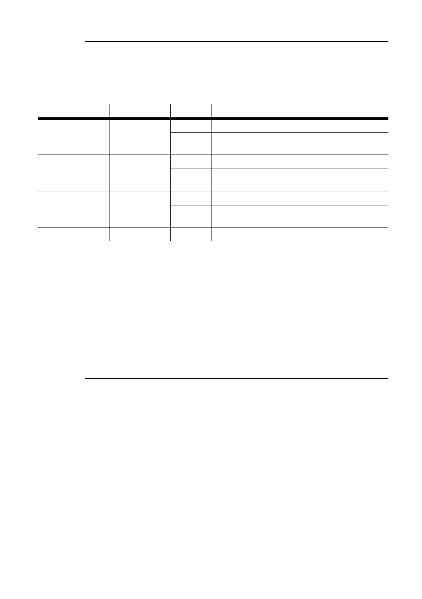
Readout Path Option Displays
Usage
Inf/Hr
tot Total hours with power on.
rES Hours with power on since counter was reset.
Recommended for tracking service intervals.
Lamp usage
Inf/LHr
tot Total hours with lamp on.
rES Hours with lamp on since counter was reset.
Recommended for tracking lamp life.
Lamp strikes
Inf/LSt
tot
Total number of lamp strikes.
rES Lamp strikes since counter was reset. Helps
evaluate lamp life.
Software version
UEr - Version number of installed software.
Table 5: Readouts
Control panel
19
To test DMX control values
1 Program a set of commands for the fixture.
2 Scroll to tSt in the main menu, press [enter] and scroll to
LOg. Press [enter].
3 Press [enter] to display the start code. The start code must be 0. Press [menu].
4 Scroll through the effects and press [enter] to display the DMX values received.
Compare the values with the DMX protocol.
UPLOAD MODE
Software upload mode is normally engaged automatically. Use this option only if
automatic upload fails. See “Installing software” on page 36.
MANUAL CONTROL
The manual control menu (Ctr) provides limited manual operation and is used to
program and execute scenes as described under “Programmed Stand-alone” on page
26. The lamp strikes automatically when you enter the menu.
To reset the fixture, select
rST.
To turn the lamp on or off, select
LOn or LOF.
See Table 7 on page 27 for additional options.
ADJUSTMENT CONTROL
The adjustment menu (AdJ) provides manual control for service use.
AUTOMATIC STAND-ALONE CONTROL
The MiniMAC can be operated without a controller in Automatic Stand-alone
mode; see page 23.
20
Controller operation
C
ONTROLLER
OPERATION
5
This section describes operation with DMX controllers. The MiniMAC is also
compatible with the Martin MC-1 and MC-X controllers.
Controller operation is disabled when a stand-alone mode is enabled.
DATA CONNECTION
RECOMMENDED CABLE
Reliable data communication begins with the right cable. Most microphone cable
does not transmit digital data reliably over long runs. For best results, use shielded,
twisted-pair cable designed for RS-485 applications with low capacitance and a
characteristic impedance of 85 to 150 ohms. The minimum wire size is 0.2 mm (24
AWG) for runs up to 300 meters (1000 ft.) and 0.322 mm (26 AWG) for runs up
500 meters (1640 ft.).
Your Martin dealer can supply the right cable in various lengths.
CONNECTIONS
The XLR data sockets are wired pin 1 to ground, pin 2 to signal - (cold), and pin 3
to signal + (hot). This is the standard pin assignment for DMX devices.
One or more adaptor cables may be required to connect the MiniMAC to the
controller and other lights if they have 5-pin connectors or reversed signal polarity
on pins 2 and 3.
Phase-Reversing
Adaptor
Male Female
1
2
3
1
2
3
3-pin to 3-pin
P/N 11820006
Adaptor
Male Female
1
2
3
4
5
1
2
3
5-pin to 3-pin
P/N 11820005
Adaptor
Male Female
1
2
3
1
2
3
4
5
3-pin to 5-pin
P/N 11820004
  • Page 1 1
  • Page 2 2
  • Page 3 3
  • Page 4 4
  • Page 5 5
  • Page 6 6
  • Page 7 7
  • Page 8 8
  • Page 9 9
  • Page 10 10
  • Page 11 11
  • Page 12 12
  • Page 13 13
  • Page 14 14
  • Page 15 15
  • Page 16 16
  • Page 17 17
  • Page 18 18
  • Page 19 19
  • Page 20 20
  • Page 21 21
  • Page 22 22
  • Page 23 23
  • Page 24 24
  • Page 25 25
  • Page 26 26
  • Page 27 27
  • Page 28 28
  • Page 29 29
  • Page 30 30
  • Page 31 31
  • Page 32 32
  • Page 33 33
  • Page 34 34
  • Page 35 35
  • Page 36 36
  • Page 37 37
  • Page 38 38
  • Page 39 39
  • Page 40 40
  • Page 41 41
  • Page 42 42
  • Page 43 43
  • Page 44 44

Martin Professional MiniMAC Wash User manual

Category
Floodlights
Type
User manual
This manual is also suitable for

Ask a question and I''ll find the answer in the document

Finding information in a document is now easier with AI