ASROCK K10N78FULLHD-HSLI User manual
- Category
- Motherboards
- Type
- User manual
This manual is also suitable for

11
11
1
K10N78FullHD-hSLI
User Manual
Version 2.0/3.0
Published March 2008
Copyright©2008 ASRock INC. All rights reserved.

22
22
2
Copyright Notice:Copyright Notice:
Copyright Notice:Copyright Notice:
Copyright Notice:
No part of this manual may be reproduced, transcribed, transmitted, or translated in
any language, in any form or by any means, except duplication of documentation by
the purchaser for backup purpose, without written consent of ASRock Inc.
Products and corporate names appearing in this manual may or may not be regis-
tered trademarks or copyrights of their respective companies, and are used only for
identification or explanation and to the owners’ benefit, without intent to infringe.
Disclaimer:Disclaimer:
Disclaimer:Disclaimer:
Disclaimer:
Specifications and information contained in this manual are furnished for informa-
tional use only and subject to change without notice, and should not be constructed
as a commitment by ASRock. ASRock assumes no responsibility for any errors or
omissions that may appear in this manual.
With respect to the contents of this manual, ASRock does not provide warranty of
any kind, either expressed or implied, including but not limited to the implied warran-
ties or conditions of merchantability or fitness for a particular purpose.
In no event shall ASRock, its directors, officers, employees, or agents be liable for
any indirect, special, incidental, or consequential damages (including damages for
loss of profits, loss of business, loss of data, interruption of business and the like),
even if ASRock has been advised of the possibility of such damages arising from any
defect or error in the manual or product.
This device complies with Part 15 of the FCC Rules. Operation is subject to the
following two conditions:
(1) this device may not cause harmful interference, and
(2) this device must accept any interference received, including interference that
may cause undesired operation.
CALIFORNIA, USA ONLY
The Lithium battery adopted on this motherboard contains Perchlorate, a toxic
substance controlled in Perchlorate Best Management Practices (BMP) regulations
passed by the California Legislature. When you discard the Lithium battery in
California, USA, please follow the related regulations in advance.
“Perchlorate Material-special handling may apply, see
www.dtsc.ca.gov/hazardouswaste/perchlorate”
ASRock Website: http://www.asrock.com

33
33
3
ContentsContents
ContentsContents
Contents
1.1.
1.1.
1.
IntroductionIntroduction
IntroductionIntroduction
Introduction
......................................................................................................................
......................................................................................................................
...........................................................
5 5
5 5
5
1.1 Package Contents ..................................................................... 5
1.2 Specifications ........................................................................... 6
1.3 Minimum Hardware Requirement Table for Windows
®
Vista
TM
Premium 2008 and Basic Logo .................................................. 10
1.4 Minimum Hardware Requirement for 1080p Blu-ray (BD) /
HD-DVD Playback Support ......................................................... 11
1.5 1080p Blu-ray (BD) / HD-DVD Films Which Pass Our Lab Test . 12
1.6 Motherboard Layout (K10N78FullHD-hSLI R2.0) ........................ 13
1.7 Motherboard Layout (K10N78FullHD-hSLI R3.0) ........................ 14
1.8 ASRock 6CH_DVI I/O Plus ........................................................ 15
2.2.
2.2.
2.
InstallationInstallation
InstallationInstallation
Installation
..........................................................................................................................
..........................................................................................................................
.............................................................
16 16
16 16
16
Pre-installation Precautions ................................................................ 16
2.1 CPU Installation ......................................................................... 17
2.2 Installation of CPU Fan and Heatsink ......................................... 17
2.3 Installation of Memory Modules (DIMM) .................................... 18
2.4 Expansion Slots (PCI and PCI Express Slots) .................................. 19
2.5 Hybrid SLI
TM
Operation Guide .................................................... 21
2.6 Dual Monitor and Surround Display Features ............................. 25
2.7 HDMI Audio Function Operation Guide ...................................... 29
2.8 Jumpers Setup .......................................................................... 30
2.9 Onboard Headers and Connectors ............................................. 31
2.10 HDMI_SPDIF Header Connection Guide .................................... 35
2.11 SATAII Hard Disk Setup Guide ................................................... 36
2.12 Serial ATA (SATA) / Serial ATAII (SATAII) Hard Disks
Installation ................................................................................. 37
2.13 Hot Plug and Hot Swap Functions for SATA / SATAII HDDs ....... 37
2.14 SATA / SATAII HDD Hot Plug Feature and Operation Guide ....... 38
2.15 Driver Installation Guide ............................................................. 40
2.16 Installing Windows
®
XP / XP 64-bit / Vista
TM
/ Vista
TM
64-bit
Without RAID Functions ............................................................ 40
2.16.1 Installing Windows
®
XP / XP 64-bit Without RAID
Functions ...................................................................... 40
2.16.2 Installing Windows
®
Vista
TM
/ Vista
TM
64-bit Without RAID
Functions ...................................................................... 41
2.17 Installing Windows
®
XP / XP 64-bit / Vista
TM
/ Vista
TM
64-bit
With RAID Functions ................................................................. 42
2.17.1 Installing Windows
®
XP / XP 64-bit With RAID Functions 42
2.17.2 Installing Windows
®
Vista
TM
/ Vista
TM
64-bit With RAID
Functions ...................................................................... 43

44
44
4
2.18 Untied Overclocking Technology ................................................ 44
3.3.
3.3.
3.
BIOS SBIOS S
BIOS SBIOS S
BIOS S
ETUP UTILITYETUP UTILITY
ETUP UTILITYETUP UTILITY
ETUP UTILITY
....................................................................................................
....................................................................................................
..................................................
45 45
45 45
45
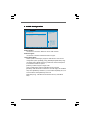
3.1 Introduction ................................................................................ 45
3.1.1 BIOS Menu Bar ............................................................... 45
3.1.2 Navigation Keys .............................................................. 46
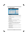
3.2 Main Screen .............................................................................. 46
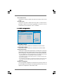
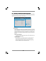
3.3 Advanced Screen ....................................................................... 47
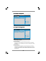
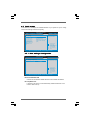
3.3.1 CPU Configuration ........................................................... 47
3.3.2 Chipset Configuration ...................................................... 52
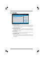
3.3.3 ACPI Configuration .......................................................... 54
3.3.4 IDE Configuration ............................................................. 55
3.3.5 PCIPnP Configuration ...................................................... 57
3.3.6 Floppy Configuration ........................................................ 58
3.3.7 Super IO Configuration .................................................... 58
3.3.8 USB Configuration ........................................................... 59
3.4 Hardware Health Event Monitoring Screen ................................. 60
3.5 Boot Screen .............................................................................. 61
3.5.1 Boot Settings Configuration ............................................. 61
3.6 Security Screen ......................................................................... 62
3.7 Exit Screen ................................................................................ 63
4.4.
4.4.
4.
Software SupportSoftware Support
Software SupportSoftware Support
Software Support
......................................................................................................
......................................................................................................
...................................................
64 64
64 64
64
4.1 Install Operating System ........................................................... 64
4.2 Support CD Information .............................................................. 64
4.2.1 Running Support CD ........................................................ 64
4.2.2 Drivers Menu ................................................................... 64
4.2.3 Utilities Menu .................................................................. 64
4.2.4 Contact Information .......................................................... 64

55
55
5
1.1.
1.1.
1.
IntroductionIntroduction
IntroductionIntroduction
Introduction
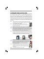
Thank you for purchasing ASRock K10N78FullHD-hSLI motherboard, a reliable
motherboard produced under ASRock’s consistently stringent quality control. It delivers
excellent performance with robust design conforming to ASRock’s commitment to qual-
ity and endurance.
In this manual, chapter 1 and 2 contain introduction of the motherboard and step-by-step
guide to the hardware installation. Chapter 3 and 4 contain the configuration guide to
BIOS setup and information of the Support CD.
Because the motherboard specifications and the BIOS software might be
updated, the content of this manual will be subject to change without
notice. In case any modifications of this manual occur, the updated
version will be available on ASRock website without further notice. You
may find the latest VGA cards and CPU support lists on ASRock website
as well. ASRock website
http://www.asrock.com
If you require technical support related to this motherboard, please visit
our website for specific information about the model you are using.
www.asrock.com/support/index.asp
1.11.1
1.11.1
1.1
PP
PP
P
ackack
ackack
ack
age Contentsage Contents
age Contentsage Contents
age Contents
1 x ASRock K10N78FullHD-hSLI Motherboard
(Micro ATX Form Factor: 9.6-in x 9.6-in, 24.4 cm x 24.4 cm)
1 x ASRock K10N78FullHD-hSLI Quick Installation Guide
1 x ASRock K10N78FullHD-hSLI Support CD
1 x Ultra ATA 66/100/133 IDE Ribbon Cable (80-conductor)
1 x 3.5-in Floppy Drive Ribbon Cable
1 x Serial ATA (SATA) Data Cable (Optional)
1 x Serial ATA (SATA) HDD Power Cable (Optional)
1 x HDMI_SPDIF Cable (Optional)
1 x “ASRock 6CH_DVI I/O Plus” I/O Shield

66
66
6
1.21.2
1.21.2
1.2
SpecificationsSpecifications
SpecificationsSpecifications
Specifications
Platform - Micro ATX Form Factor: 9.6-in x 9.6-in, 24.4 cm x 24.4 cm
CPU - Support for Socket AM2+ / AM2 processors: AMD Phenom
TM
FX / Phenom / Athlon 64 FX / Athlon 64 X2 Dual-Core / Athlon
X2 Dual-Core / Athlon 64 / Sempron
processor
- AMD LIVE!
TM
Ready
- Supports AMD’s Cool ‘n’ Quiet
TM
Technology
- FSB 2600 MHz (5.2 GT/s) (see CAUTION 1)
- Supports Untied Overclocking Technology (see CAUTION 2)
- Supports Hyper-Transport 3.0 (HT 3.0) Technology
Chipset - NVIDIA
®
GeForce 8200
Memory - Dual Channel DDR2 Memory Technology (see CAUTION 3)
- 4 x DDR2 DIMM slots
- Support DDR2 1066/800/667/533 non-ECC, un-buffered memory
(see CAUTION 4)
- Max. capacity of system memory: 8GB (see CAUTION 5)
Expansion Slot - 1 x PCI Express 2.0 x16 slot (green @ x16 mode)
- 1 x PCI Express x1 slot
- 2 x PCI slots
- Supports NVIDIA
®
Hybrid SLI
TM
(see CAUTION 6)
Graphics - Integrated NVIDIA
®
GeForce8 Series
- DX10 VGA, Pixel Shader 4.0
- Max. shared memory 512MB (see CAUTION 7)
- Dual VGA Output: support DVI-D and D-Sub ports by
independent display controllers
- Supports HDCP function with DVI-D port
- Supports 1080p Blu-ray (BD) / HD-DVD playback with
DVI-D port (see CAUTION 8)
- NVIDIA
®
PureVideo
TM
HD Ready
Audio - 5.1 CH Windows
®
Vista
TM
Premium Level HD Audio
(ALC662 Audio Codec)
- Chipset embeded HDMI Audio
LAN - K10N78FullHD-hSLI R2.0
Realtek PHY RTL8201CL, speed 10/100 Mb/s
- K10N78FullHD-hSLI R3.0
Realtek Giga PHY RTL8211B, speed 10/100/1000 Mb/s
- Supports Wake-On-LAN
Rear Panel I/O ASRock 6CH_DVI I/O Plus
- 1 x PS/2 Mouse Port
- 1 x PS/2 Keyboard Port

77
77
7
- 1 x VGA/D-Sub Port
- 1 x VGA/DVI-D Port (see CAUTION 9)
- 6 x Ready-to-Use USB 2.0 Ports
- 1 x RJ-45 Port
- HD Audio Jack: Line in/Front Speaker/Microphone
Connector - 6 x Serial ATAII 3.0Gb/s connectors, support RAID (RAID 0,
RAID 1, RAID 0+1, RAID 5 and JBOD), NCQ, AHCI and
“Hot Plug” functions (see CAUTION 10)
- 1 x ATA133 IDE connector (supports 2 x IDE devices)
- 1 x Floppy connector
- 1 x DeskExpress Hot Plug Detection header
- 1 x COM port header
- 1 x HDMI_SPDIF header
- CPU/Chassis FAN connector
- 24 pin ATX power connector
- 4 pin 12V power connector
- CD in header
- Front panel audio header
- 2 x USB 2.0 headers (support 4 USB 2.0 ports)
(see CAUTION 11)
- 1 x WiFi/E header (see CAUTION 12)
BIOS Feature - 4Mb AMI BIOS
- AMI Legal BIOS
- Supports “Plug and Play”
- ACPI 1.1 Compliance Wake Up Events
- Supports jumperfree
- SMBIOS 2.3.1 Support
Support CD - Drivers, Utilities, AntiVirus Software (Trial Version)
Unique Feature - ASRock OC Tuner (see CAUTION 13)
- Intelligent Energy Saver (see CAUTION 14)
- Hybrid Booster:
- CPU Frequency Stepless Control (see CAUTION 15)
- ASRock U-COP (see CAUTION 16)
- Boot Failure Guard (B.F.G.)
- ASRock AM2 Boost: ASRock Patented Technology to boost
memory performance up to 12.5% (see CAUTION 17)
Hardware - CPU Temperature Sensing
Monitor - Chassis Temperature Sensing
- CPU Fan Tachometer
- Chassis Fan Tachometer
- CPU Quiet Fan
- Voltage Monitoring: +12V, +5V, +3.3V, Vcore

88
88
8
WARNING
Please realize that there is a certain risk involved with overclocking, including adjusting
the setting in the BIOS, applying Untied Overclocking Technology, or using the third-
party overclocking tools. Overclocking may affect your system stability, or even
cause damage to the components and devices of your system. It should be done at
your own risk and expense. We are not responsible for possible damage caused by
overclocking.
CAUTION!
1. If you install AM2 CPU on this motherbord, the system bus speed will be
HT1.0 (2000 MT/s). If you install AM2+ CPU on this motherbord, the system
bus speed will be HT3.0 (up to 5200 MT/s), and the HT Link frequency
depends on the ability of the AM2+ CPU you adopt. Please refer to the CPU
support list on our website for more information.
ASRock website
http://www.asrock.com
2. This motherboard supports Untied Overclocking Technology. Please read
“Untied Overclocking Technology” on page 44 for details.
3. This motherboard supports Dual Channel Memory Technology. Before
you implement Dual Channel Memory Technology, make sure to read
the installation guide of memory modules on page 18 for proper
installation.
4. Whether 1066MHz memory speed is supported depends on the AM2+
CPU you adopt. If you want to adopt DDR2 1066 memory module on this
motherboard, please refer to the memory support list on our website for
the compatible memory modules.
ASRock website
http://www.asrock.com
5. Due to the operating system limitation, the actual memory size may be
less than 4GB for the reservation for system usage under Windows
®
XP
and Windows
®
Vista
TM
. For Windows
®
XP 64-bit and Windows
®
Vista
TM
64-
bit with 64-bit CPU, there is no such limitation.
6. Hybrid SLI
TM
feature should depend on the driver from NVIDIA
®
and it may
be updated in the near future. Currently, the Hybrid SLI
TM
driver in our sup-
port CD is beta driver provided by NVIDIA
®
. As long as we have the latest
Hybrid SLI
TM
driver, we will update it to our website. Please visit our website
for Hybrid SLI
TM
driver in the future. For the current operation procedures,
please refer to “Hybrid SLI
TM
Operation Guide” on page 21.
7. The maximum shared memory size is defined by the chipset vendor
and is subject to change. Please check NVIDIA
®
website for the latest
information.
8. 1080p Blu-ray (BD) / HD-DVD playback support on this motherboard re-
quires the proper hardware configuration. Please refer to page11 and 12
for the minimum hardware requirement and the passed 1080p Blu-ray
(BD) / HD-DVD films in our lab test.
OS - Microsoft
®
Windows
®
XP / XP Media Center / XP 64-bit /
Vista
TM
/ Vista
TM
64-bit compliant
Certifications - FCC, CE, Microsoft
®
WHQL Certificated
* For detailed product information, please visit our website: http://www.asrock.com

99
99
9
9. This DVI-D port for the chipset adopted on this motherboard can support
DVI/HDCP and HDMI format signal. You may use the DVI to HDMI adapter to
convert this DVI-D port to HDMI interface. DVI to HDMI adapter is not bundled
with our product, please refer to the adapter vendor for further information.
10. Before installing SATAII hard disk to SATAII connector, please read the “SATAII
Hard Disk Setup Guide” on page 36 to adjust your SATAII hard disk drive to
SATAII mode. You can also connect SATA hard disk to SATAII connector
directly.
11. Power Management for USB 2.0 works fine under Microsoft
®
Windows
®
Vista
TM
64-bit / Vista
TM
/ XP 64-bit / XP SP1 or SP2.
12. WiFi/E header supports WiFi+AP function with ASRock WiFi-802.11g or
WiFi-802.11n module, an easy-to-use wireless local area network
(WLAN) adapter. It allows you to create a wireless environment and
enjoy the convenience of wireless network connectivity. Please visit our
website for the availability of ASRock WiFi-802.11g or WiFi-802.11n
module. ASRock website http://www.asrock.com
13. It is a user-friendly ASRock overclocking tool which allows you to surveil
your system by hardware monitor function and overclock your hardware
devices to get the best system performance under Windows
®
environment. Please visit our website for the operation procedures of
ASRock OC Tuner. ASRock website:
http://www.asrock.com
14. Featuring an advanced proprietary hardware and software design, Intel-
ligent Energy Saver is one of the options in ASRock OC Tuner. The
voltage regulator can reduce the number of output phases to improve
efficiency when the CPU cores are idle. In other words, it is able to
provide exceptional power saving and improve power efficiency without
sacrificing computing performance. To use Intelligent Energy Saver
function, please enable Cool ‘n’ Quiet option in the BIOS setup in
advance. Please visit our website for the operation procedures of Intel-
ligent Energy Saver. ASRock website:
http://www.asrock.com
15. Although this motherboard offers stepless control, it is not recom-
mended to perform over-clocking. Frequencies other than the recom-
mended CPU bus frequencies may cause the instability of the system
or damage the CPU.
16. While CPU overheat is detected, the system will automatically shutdown.
Before you resume the system, please check if the CPU fan on the
motherboard functions properly and unplug the power cord, then plug it
back again. To improve heat dissipation, remember to spray thermal
grease between the CPU and the heatsink when you install the PC
system.
17. This motherboard supports ASRock AM2 Boost overclocking technology. If
you enable this function in the BIOS setup, the memory performance will
improve up to 12.5%, but the effect still depends on the AM2 CPU you
adopt. Enabling this function will overclock the chipset/CPU reference clock.
However, we can not guarantee the system stability for all CPU/DRAM
configurations. If your system is unstable after AM2 Boost function is enabled,
it may not be applicative to your system. You may choose to disable this
function for keeping the stability of your system.

1010
1010
10
1.31.3
1.31.3
1.3
Minimum Hardware RMinimum Hardware R
Minimum Hardware RMinimum Hardware R
Minimum Hardware R
equirement Tequirement T
equirement Tequirement T
equirement T
able for Wable for W
able for Wable for W
able for W
indowsindows
indowsindows
indows
®®
®®
®
VistaVista
VistaVista
Vista
TMTM
TMTM
TM
Premium 2008 and Basic Logo Premium 2008 and Basic Logo
Premium 2008 and Basic Logo Premium 2008 and Basic Logo
Premium 2008 and Basic Logo
For system integrators and users who purchase this motherboard and
plan to submit Windows
®
Vista
TM
Premium 2008 and Basic logo, please follow
below table for minimum hardware requirements.
CPU Sempron 2800+
Memory 512MB x 2 Dual Channel (Premium)
512MB Single Channel (Basic)
256MB x 2 Dual Channel (Basic)
VGA DX10 with WDDM Driver
DVI with HDCP
* If you use onboard VGA with total system memory size 512MB and plan to
submit Windows
®
Vista
TM
Basic logo, please adjust the shared memory size of onboard
VGA to 64MB. If you use onboard VGA with total system memory size above 512MB
and plan to submit Windows
®
Vista
TM
Premium or Basic logo, please adjust the shared
memory size of onboard VGA to 128MB or above.
* If you plan to use external graphics card on this motherboard, please refer to Premium
Discrete requirement at
http://www.asrock.com
* If the onboard VGA supports DVI, it must also support HDCP function to qualify for
Windows
®
Vista
TM
Premium 2008 logo.
* After June 1, 2008, all Windows
®
Vista
TM
systems are required to meet above
minimum hardware requirements in order to qualify for Windows
®
Vista
TM
Premium
2008 logo.

1111
1111
11
1.41.4
1.41.4
1.4
Minimum Hardware Requirement for 1080p Blu-rayMinimum Hardware Requirement for 1080p Blu-ray
Minimum Hardware Requirement for 1080p Blu-rayMinimum Hardware Requirement for 1080p Blu-ray
Minimum Hardware Requirement for 1080p Blu-ray
(BD) / HD(BD) / HD
(BD) / HD(BD) / HD
(BD) / HD
-D-D
-D-D
-D
VD Playback SupporVD Playback Suppor
VD Playback SupporVD Playback Suppor
VD Playback Suppor
tt
tt
t
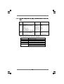
1080p Blu-ray (BD) / HD-DVD playback support on this motherboard
requires the proper hardware configuration. Please refer to below table
for the minimum hardware requirement.
CPU AMD Phenom X3 8400
VGA Onboard VGA with DVI-D port
Memory Dual Channel DDR2 533, 1GB x 2
Suggested OS Windows
®
Vista
TM
or Windows
®
Vista
TM
64
* Currently, 1080p Blu-ray (BD) / HD-DVD playback is only supported under Windows
®
Vista
TM
/ Vista
TM
64-bit OS. If you install Windows
®
XP / XP 64-bit OS, the function of
1080p Blu-ray (BD) / HD-DVD playback is not available, please visit our website for
NVIDIA
®
driver update in the future.
ASRock website
http://www.asrock.com

1212
1212
12
1.51.5
1.51.5
1.5
PP
PP
P
assed 1080p Blu-ray (BD) / HDassed 1080p Blu-ray (BD) / HD
assed 1080p Blu-ray (BD) / HDassed 1080p Blu-ray (BD) / HD
assed 1080p Blu-ray (BD) / HD
-D-D
-D-D
-D
VD FVD F
VD FVD F
VD F
ilms in Our Lilms in Our L
ilms in Our Lilms in Our L
ilms in Our L
abab
abab
ab
TT
TT
T
estest
estest
est
DVD Film Name Format Producer
Type
Blu-ray SWORDFISH VC-1 WB
DVD UNDERWORLD EVOLUTION MPEG-2 SONY
X-MEN III MPEG-4-AVC FOX
SPEED MPEG-4-AVC FOX
CASINO ROYALE MPEG-4-AVC SONY
THE LEAGUE OF MPEG-4-AVC FOX
EXTRAORDINARY GENTLEMEN
HD- KING KONG VC-1 UNIVERSAL
DVD NEW ORLEANS CONCERT MPEG-2 WEA
ONE SIX RIGHT MPEG-2 TERWILLIGER
* MPEG-4-AVC mentioned above refers to the same format of H.264.
* Above passed films are tested under below configuration.
Items Configurations
CPU AMD Phenom X3 8400
VGA Onboard VGA with DVI-D port
Memory Dual Channel DDR2 533, 1GB x 2
OS Windows
®
Vista
TM
or Windows
®
Vista
TM
64
Playback Software CyberLink PowerDVD Ultra
DVD Player Blu-ray-DVDRW-LG-GBW-H10N (BD)
HD DVD-HP-TOSD-H802A-01 (HD-DVD)

1313
1313
13
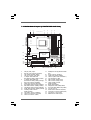
1.6 Motherboard L1.6 Motherboard L
1.6 Motherboard L1.6 Motherboard L
1.6 Motherboard L
ayout (K10N78Fayout (K10N78F
ayout (K10N78Fayout (K10N78F
ayout (K10N78F
ullHDullHD
ullHDullHD
ullHD
-hSLI R2.0)-hSLI R2.0)
-hSLI R2.0)-hSLI R2.0)
-hSLI R2.0)
Super
I/O
PCI
EXPRESS
CMOS
BATTERY
ATXPWR1
SOCKET AM2
K10N78FullHD-hSLI
CD1
NVIDIA
GeForce 8200
Chipset
ATX12V1
PS2_USB_PW1
1
COM1
IDE1
FSB800
DDRII_1 (64 bit, 240-pin module)
DDRII_2 (64 bit, 240-pin module)
FSB800
DDRII_3 (64 bit, 240-pin module)
DDRII_4 (64 bit, 240-pin module)
PCIE1
PCI1
PCI2
LAN
PHY
AUDIO
CODEC
1
CLRCMOS1
1
Dual Channel
RAID
CPU_FAN1
HDLED RESET
PLED PWRBTN
1
PANEL1
CHA_FAN1
SPEAKER1
1
FLOPPY1
HD_AUDIO1
1
RoHS
24.4cm (9.6-in)
24.4cm (9.6-in)
6
7
1
2
43
5
8
9
10
11
12
13
14
15
16
17
18
19
20
2122
23
24
25
26
27
28
29
PCIE2
USB8_9
1
1
HDMI_SPDIF1
30
31
32
USB6_7
1
USB 2.0
T: USB4
B: USB5
USB 2.0
T: USB0
B: USB1
Top:
RJ-45
Top:
LINE IN
Center:
FRONT
Bottom:
MIC IN
DVI_CON1
PS2
Mouse
PS2
Keyboard
VGA1
DVI
HDCP
4Mb
BIOS
WIFI/E
1
SATAII_1(PORT0) SATAII_3(PORT2) SATAII_5(PORT4)
IR1
1
DDR2 800
AM2+
SATAII
FSB2.6GHz
SATAII_2(PORT1) SATAII_4(PORT3) SATAII_6(PORT5)
USB 2.0
T: USB2
B: USB3
PCI Express 2.0
33
1 PS2_USB_PW1 Jumper 17 DeskExpress Hot Plug Detection Header
2 ATX 12V Power Connector (ATX12V1) (IR1)
3 CPU Heatsink Retention Module 18 Floppy Connector (FLOPPY1)
4 CPU Fan Connector (CPU_FAN1) 19 System Panel Header (PANEL1)
5 2 x 240-pin DDR2 DIMM Slots 20 Chassis Speaker Header (SPEAKER 1)
(Dual Channel A: DDRII_1, DDRII_2; Yellow) 21 SPI Flash Memory (4Mb)
6 2 x 240-pin DDR2 DIMM Slots 22 USB 2.0 Header (USB8_9, Blue)
(Dual Channel B: DDRII_3, DDRII_4; Orange) 23 USB 2.0 Header (USB6_7, Blue)
7 ATX Power Connector (ATXPWR1) 24 Primary SATAII Connector
8 Primary IDE Connector (IDE1, Blue) (SATAII_1 (PORT0))
9 Third SATAII Connector (SATAII_3 (PORT2)) 25 WiFi/E Header (WIFI/E)
10 Fifth SATAII Connector (SATAII_5 (PORT4)) 26 HDMI_SPDIF Header (HDMI_SPDIF1)
11 Sixth SATAII Connector (SATAII_6 (PORT5)) 27 Front Panel Audio Header (HD_AUDIO1)
12 Fourth SATAII Connector (SATAII_4 (PORT3)) 28 PCI Slots (PCI1- 2)
13 Secondary SATAII Connector 29 Internal Audio Connector: CD1 (Black)
(SATAII_2 (PORT1)) 30 PCI Express 2.0 x16 Slot (PCIE2; Green)
14 Clear CMOS Jumper (CLRCMOS1) 31 PCI Express x1 Slot (PCIE1)
15 Chassis Fan Connector (CHA_FAN1) 32 NVIDIA GeForce 8200 Chipset
16 Serial Port Connector (COM1)

1414
1414
14
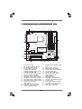
1.7 Motherboard L1.7 Motherboard L
1.7 Motherboard L1.7 Motherboard L
1.7 Motherboard L
ayout (K10N78Fayout (K10N78F
ayout (K10N78Fayout (K10N78F
ayout (K10N78F
ullHDullHD
ullHDullHD
ullHD
-hSLI R3.0)-hSLI R3.0)
-hSLI R3.0)-hSLI R3.0)
-hSLI R3.0)
Super
I/O
PCI
EXPRESS
CMOS
BATTERY
ATXPWR1
SOCKET AM2
K10N78FullHD-hSLI
CD1
NVIDIA
GeForce 8200
Chipset
ATX12V1
PS2_USB_PW1
1
COM1
IDE1
FSB800
DDRII_1 (64 bit, 240-pin module)
DDRII_2 (64 bit, 240-pin module)
FSB800
DDRII_3 (64 bit, 240-pin module)
DDRII_4 (64 bit, 240-pin module)
PCIE1
PCI1
PCI2
LAN
PHY
AUDIO
CODEC
1
CLRCMOS1
1
Dual Channel
RAID
CPU_FAN1
HDLED RESET
PLED PWRBTN
1
PANEL1
CHA_FAN1
SPEAKER1
1
FLOPPY1
HD_AUDIO1
1
RoHS
24.4cm (9.6-in)
24.4cm (9.6-in)
6
7
1
2
43
5
8
9
10
11
12
13
14
15
16
17
18
19
20
2122
23
24
25
26
27
28
29
PCIE2
USB8_9
1
1
HDMI_SPDIF1
30
31
32
USB6_7
1
USB 2.0
T: U SB 4
B: USB5
USB 2.0
T: U SB 0
B: USB1
Top:
RJ-45
Top:
LINE IN
Center:
FRONT
Bottom:
MIC IN
PS2
Mouse
PS2
Keyboard
DVI
HDCP
4Mb
BIOS
WIFI/E
1
IR1
1
DDR2 800
AM2+
SATAII
FSB2.6GHz
USB 2.0
T: U SB 2
B: USB3
PCI Express 2.0
SATAII_1(PORT0) SATAII_3(PORT2) SATAII_5(PORT4)
SATAII_2(PORT1) SATAII_4(PORT3) SATAII_6(PORT5)
33
DVI_CON1
VGA1
1 PS2_USB_PW1 Jumper 17 DeskExpress Hot Plug Detection Header
2 ATX 12V Power Connector (ATX12V1) (IR1)
3 CPU Heatsink Retention Module 18 Floppy Connector (FLOPPY1)
4 CPU Fan Connector (CPU_FAN1) 19 System Panel Header (PANEL1)
5 2 x 240-pin DDR2 DIMM Slots 20 Chassis Speaker Header (SPEAKER 1)
(Dual Channel A: DDRII_1, DDRII_2; Yellow) 21 SPI Flash Memory (4Mb)
6 2 x 240-pin DDR2 DIMM Slots 22 USB 2.0 Header (USB8_9, Blue)
(Dual Channel B: DDRII_3, DDRII_4; Orange) 23 USB 2.0 Header (USB6_7, Blue)
7 ATX Power Connector (ATXPWR1) 24 Primary SATAII Connector
8 Primary IDE Connector (IDE1, Blue) (SATAII_1 (PORT0))
9 Third SATAII Connector (SATAII_3 (PORT2)) 25 WiFi/E Header (WIFI/E)
10 Fifth SATAII Connector (SATAII_5 (PORT4)) 26 HDMI_SPDIF Header (HDMI_SPDIF1)
11 Sixth SATAII Connector (SATAII_6 (PORT5)) 27 Front Panel Audio Header (HD_AUDIO1)
12 Fourth SATAII Connector (SATAII_4 (PORT3)) 28 PCI Slots (PCI1- 2)
13 Secondary SATAII Connector 29 Internal Audio Connector: CD1 (Black)
(SATAII_2 (PORT1)) 30 PCI Express 2.0 x16 Slot (PCIE2; Green)
14 Clear CMOS Jumper (CLRCMOS1) 31 PCI Express x1 Slot (PCIE1)
15 Chassis Fan Connector (CHA_FAN1) 32 NVIDIA GeForce 8200 Chipset
16 Serial Port Connector (COM1)

1515
1515
15
1.81.8
1.81.8
1.8
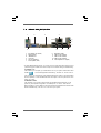
ASRock 6CH_DVI I/O PlusASRock 6CH_DVI I/O Plus
ASRock 6CH_DVI I/O PlusASRock 6CH_DVI I/O Plus
ASRock 6CH_DVI I/O Plus
1 PS/2 Mouse Port (Green) * 7 Microphone (Pink)
2 VGA/D-Sub Port 8 USB 2.0 Ports (USB45)
* 3 VGA/DVI-D Port 9 USB 2.0 Ports (USB01)
4 RJ-45 Port 10 USB 2.0 Ports (USB23)
5 Line In (Light Blue) 11 PS/2 Keyboard Port (Purple)
6 Front Speaker (Lime)
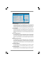
* To enable Multi-Streaming function, you need to connect a front panel audio cable to the front
panel audio header. Please refer to below steps for the software setting of Multi-Streaming.
For Windows
®
XP:
After restarting your computer, you will find “Mixer” tool on your system. Please select “Mixer
ToolBox” , click “Enable playback multi-streaming”, and click “ok”. Choose “2CH” or
“4CH” and then you are allowed to select “Realtek HDA Primary output” to use Rear Speaker
and Front Speaker, or select “Realtek HDA Audio 2nd output” to use front panel audio. Then
reboot your system.
For Windows
®
Vista
TM
:
After restarting your computer, please double-click “Realtek HD Audio Manager” on the
system tray. Set “Speaker Configuration” to “Quadraphonic” or “Stereo”. Click “Device
advanced settings”, choose “Make front and rear output devices playbacks two different audio
streams simultaneously”, and click “ok”. Then reboot your system.
1
2
4
3
5
6
7
8
9
10
11

1616
1616
16
2.2.
2.2.
2.
InstallationInstallation
InstallationInstallation
Installation
This is a Micro ATX form factor (9.6-in x 9.6-in, 24.4 cm x 24.4 cm) motherboard.
Before you install the motherboard, study the configuration of your chassis to en-
sure that the motherboard fits into it.
Pre-installation PrecautionsPre-installation Precautions
Pre-installation PrecautionsPre-installation Precautions
Pre-installation Precautions
Take note of the following precautions before you install motherboard
components or change any motherboard settings.
Before you install or remove any component, ensure that the
power is switched off or the power cord is detached from the
power supply. Failure to do so may cause severe damage to the
motherboard, peripherals, and/or components.
1. Unplug the power cord from the wall socket before touching any
component.
2. To avoid damaging the motherboard components due to static
electricity, NEVER place your motherboard directly on the carpet or
the like. Also remember to use a grounded wrist strap or touch a
safety grounded object before you handle components.
3. Hold components by the edges and do not touch the ICs.
4. Whenever you uninstall any component, place it on a grounded anti-
static pad or in the bag that comes with the component.
5. When placing screws into the screw holes to secure the motherboard
to the chassis, please do not over-tighten the screws! Doing so may
damage the motherboard.

1717
1717
17
2.12.1
2.12.1
2.1
CPU InstallationCPU Installation
CPU InstallationCPU Installation
CPU Installation
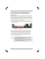
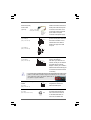
Step 1. Unlock the socket by lifting the lever up to a 90
o
angle.
Step 2. Position the CPU directly above the socket such that the CPU corner with
the golden triangle matches the socket corner with a small triangle.
Step 3. Carefully insert the CPU into the socket until it fits in place.
The CPU fits only in one correct orientation. DO NOT force the CPU
into the socket to avoid bending of the pins.
Step 4. When the CPU is in place, press it firmly on the socket while you push
down the socket lever to secure the CPU. The lever clicks on the side tab
to indicate that it is locked.
2.22.2
2.22.2
2.2
Installation of CPU Fan and HeatsinkInstallation of CPU Fan and Heatsink
Installation of CPU Fan and HeatsinkInstallation of CPU Fan and Heatsink
Installation of CPU Fan and Heatsink
After you install the CPU into this motherboard, it is necessary to install a
larger heatsink and cooling fan to dissipate heat. You also need to spray
thermal grease between the CPU and the heatsink to improve heat
dissipation. Make sure that the CPU and the heatsink are securely fas-
tened and in good contact with each other. Then connect the CPU fan to
the CPU FAN connector (CPU_FAN1, see Page 13/14, No. 4). For proper
installation, please kindly refer to the instruction manuals of the CPU fan
and the heatsink.
STEP 1:
Lift Up The Socket Lever
STEP 2 / STEP 3:
Match The CPU Golden Triangle
To The Socket Corner Small
Triangle
STEP 4:
Push Down And Lock
The Socket Lever
Lever 90° Up
CPU Golden Triangle
Socker Corner Small Triangle

1818
1818
18
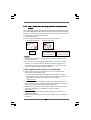
2.3 Installation of Memory Modules (DIMM)2.3 Installation of Memory Modules (DIMM)
2.3 Installation of Memory Modules (DIMM)2.3 Installation of Memory Modules (DIMM)
2.3 Installation of Memory Modules (DIMM)
This motherboard provides four 240-pin DDR2 (Double Data Rate 2) DIMM slots,
and supports Dual Channel Memory Technology. For dual channel configuration,
you always need to install identical (the same brand, speed, size and chip-type)
DDR2 DIMM pair in the slots of the same color. In other words, you have to install
identical DDR2 DIMM pair in Dual Channel A (DDRII_1 and DDRII_2; Yellow slots;
see p.13/14 No.5) or identical DDR2 DIMM pair in Dual Channel B (DDRII_3 and
DDRII_4; Orange slots; see p.13/14 No.6), so that Dual Channel Memory Technol-
ogy can be activated. This motherboard also allows you to install four DDR2 DIMMs
for dual channel configuration, and please install identical DDR2 DIMMs in all four
slots. You may refer to the Dual Channel Memory Configuration Table below.
Dual Channel Memory Configurations
DDRII_1 DD RII_2 DDRII_3 DDRII_4
(Yellow Slot) (Yellow Slot) (Orange Slot) (Orange Slot)
(1) Populated Populated - -
(2) - - Populated Populated
(3)* Populated Populated Populated Populated
* For the configuration (3), please install identical DDR2 DIMMs in all four slots.
1. If you want to install two memory modules, for optimal compatibility
and reliability, it is recommended to install them in the slots of the
same color. In other words, install them either in the set of yellow
slots (DDRII_1 and DDRII_2), or in the set of orange slots (DDRII_3
and DDRII_4).
2. If only one memory module or three memory modules are installed
in the DDR2 DIMM slots on this motherboard, it is unable to acti-
vate the Dual Channel Memory Technology.
3. If a pair of memory modules is NOT installed in the same Dual
Channel, for example, installing a pair of memory modules in DDRII_1
and DDRII_3, it is unable to activate the Dual Channel Memory
Technology .
4. It is not allowed to install a DDR memory module into DDR2 slot;
otherwise, this motherboard and DIMM may be damaged.

1919
1919
19
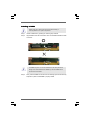
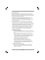
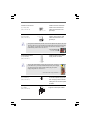
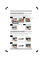
notch
break
notch
break
Installing a DIMMInstalling a DIMM
Installing a DIMMInstalling a DIMM
Installing a DIMM
Please make sure to disconnect power supply before adding or
removing DIMMs or the system components.
Step 1. Unlock a DIMM slot by pressing the retaining clips outward.
Step 2. Align a DIMM on the slot such that the notch on the DIMM matches the break
on the slot.
The DIMM only fits in one correct orientation. It will cause permanent
damage to the motherboard and the DIMM if you force the DIMM into the
slot at incorrect orientation.
Step 3. Firmly insert the DIMM into the slot until the retaining clips at both ends fully
snap back in place and the DIMM is properly seated.

2020
2020
20
2.4 Expansion Slots (PCI and PCI Express Slots)2.4 Expansion Slots (PCI and PCI Express Slots)
2.4 Expansion Slots (PCI and PCI Express Slots)2.4 Expansion Slots (PCI and PCI Express Slots)
2.4 Expansion Slots (PCI and PCI Express Slots)
There are 2 PCI slots and 2 PCI Express slots on this motherboard.
PCI slots: PCI slots are used to install expansion cards that have the 32-bit PCI
interface.
PCIE slots: PCIE1 (PCIE x1 slot) is used for PCI Express cards with x1 lane width
cards, such as Gigabit LAN card, SATA2 card, etc.
PCIE2 (PCIE x16 slot) is used for PCI Express cards with x16 lane
width graphics cards.
Installing an expansion cardInstalling an expansion card
Installing an expansion cardInstalling an expansion card
Installing an expansion card
Step 1. Before installing the expansion card, please make sure that the power
supply is switched off or the power cord is unplugged. Please read the
documentation of the expansion card and make necessary hardware
settings for the card before you start the installation.
Step 2. Remove the bracket facing the slot that you intend to use. Keep the screws
for later use.
Step 3. Align the card connector with the slot and press firmly until the card is
completely seated on the slot.
Step 4. Fasten the card to the chassis with screws.
Page is loading ...
Page is loading ...
Page is loading ...
Page is loading ...
Page is loading ...
Page is loading ...
Page is loading ...
Page is loading ...
Page is loading ...
Page is loading ...
Page is loading ...
Page is loading ...
Page is loading ...
Page is loading ...
Page is loading ...
Page is loading ...
Page is loading ...
Page is loading ...
Page is loading ...
Page is loading ...
Page is loading ...
Page is loading ...
Page is loading ...
Page is loading ...
Page is loading ...
Page is loading ...
Page is loading ...
Page is loading ...
Page is loading ...
Page is loading ...
Page is loading ...
Page is loading ...
Page is loading ...
Page is loading ...
Page is loading ...
Page is loading ...
Page is loading ...
Page is loading ...
Page is loading ...
Page is loading ...
Page is loading ...
Page is loading ...
Page is loading ...
Page is loading ...
-
 1
1
-
 2
2
-
 3
3
-
 4
4
-
 5
5
-
 6
6
-
 7
7
-
 8
8
-
 9
9
-
 10
10
-
 11
11
-
 12
12
-
 13
13
-
 14
14
-
 15
15
-
 16
16
-
 17
17
-
 18
18
-
 19
19
-
 20
20
-
 21
21
-
 22
22
-
 23
23
-
 24
24
-
 25
25
-
 26
26
-
 27
27
-
 28
28
-
 29
29
-
 30
30
-
 31
31
-
 32
32
-
 33
33
-
 34
34
-
 35
35
-
 36
36
-
 37
37
-
 38
38
-
 39
39
-
 40
40
-
 41
41
-
 42
42
-
 43
43
-
 44
44
-
 45
45
-
 46
46
-
 47
47
-
 48
48
-
 49
49
-
 50
50
-
 51
51
-
 52
52
-
 53
53
-
 54
54
-
 55
55
-
 56
56
-
 57
57
-
 58
58
-
 59
59
-
 60
60
-
 61
61
-
 62
62
-
 63
63
-
 64
64


ASROCK K10N78FULLHD-HSLI User manual
- Category
- Motherboards
- Type
- User manual
- This manual is also suitable for
Ask a question and I''ll find the answer in the document
Finding information in a document is now easier with AI
Related papers
-
ASROCK A780FULLHD User manual
-
ASROCK K10N78M PRO Owner's manual
-
ASROCK K10N78D User manual
-
-
ASROCK N68PV-GS Owner's manual
-
ASROCK N61P-S Owner's manual
-
ASROCK A780FULLDISPLAYPORT_858 Owner's manual
-
-
ASROCK A780LM-S User manual
-
ASROCK A330GC User manual
Other documents
-
PNY B-GMGTX26N2F89S2PB-G Datasheet
-
M-Cab 7070018 Datasheet
-
DeLOCK 61787 Datasheet
-
Novell CLIENT FOR LINUX 2.0 SP1 - 08-19-2008 User manual
-
Nvidia MCP55 Owner's manual
-
Sitecom MD-209 Datasheet
-
EVGA 113-M2-E113-TR Datasheet
-
Gigabyte GA-MA69GM-S2H Datasheet
-
Gigabyte Computer Hardware GA-M52S-S3P User manual
-
Foxconn C51XEM2AA User manual