Page is loading ...

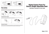
Auxiliary electric heat
power supply knockout
opposite air coil
Electric Heat Assembly
Air Coil
Low Voltage control harness
is prewired on all distributor
class units.
*
Auxiliary electric heat
power supply knockout
opposite air coil
Electric Heat Assembly
Air Coil
Low Voltage control
harness is factory installed.
Auxiliary Electric Heat
Installation, Operation & Maintenance Instructions
Figure 1: Typical Vertical External Mount Installation
HG Series Electric Heaters
Overview
The HG Series Auxiliary Electric Heat mounts externally
to the blower outlet of all HP and HE. For the HT Series it
mounts externally on the horizontals and internally on the
vertical upow and downow units. It mounts internally
on all WDG units.Note model compatibility Table 1. Units
are rated for zero clearance at the unit and 1” clearance for
rst three feet of duct. The discharge plenum should make
a 90° turn after leaving the unit and be constructed from
non combustible material. The HG electric heat contains a
four stage relay control board which activates the elements
directly via an internally wired low voltage harness. Low
voltage signals (W1 and W2) are staged from the CXM
(AXM on WDG Series) control of the unit.
HG Installation - External Mount
1. Disconnect power to the unit.
2. Remove blower access panel(s) from the unit and
control box and element covers from the electric heater.
3. Locate remove and discard blower discharge anges
from the unit but save the screws. Flanges will be
packaged loose inside the blower compartment of
vertical upow units and will be factory installed on
horizontal units, downow units have none. HE036
and 042 units require a transition bracket between
the cabinet panel and the electric heater. This bracket
is packaged inside the blower compartment for eld
installation.
4. Position the electric heater as illustrated herein.
Heater control box should be facing the front access
panel of vertical units. For horizontal units notice that
the discharge air opening is off centered in the blower
panel. The electric heater must be positioned so that
its control box is located vertically over the wide side
of this panel.
The electric heater air inlet dimensions should match
the unit air outlet, installer should stop and refer
to the unit/heater compatibility chart later in this
instruction or consult factory if they do not match.
5. Use the saved blower ange screws to attach the
heater by its anges to the unit panel except do not
fasten ange on control box side.
6. Use aluminum tape (not provided) to seal all four
heater anges to the blower panel.
7. Locate and route the low voltage control harness
through one of the unit corner post or blower panel
knockout(s). Seal the penetration ‘air tight’.
8. Route the control harness through one of the ‘pie’
bushings in the heater control box and plug on to the
P2 connector. See gure 3.
9. Install power conduit and attach directly to the
electric heater control box. See gures 5a-c.
10. Replace all covers and panels, heater installation is
complete. Proceed to wiring and setup.
Figure 1a: Typical Vertical Internal Mount

Page 2
HG Installation - Internal Mount
1. Disconnect power to the unit.
2. Remove blower access panel(s) from the unit and
control box cover from the electric heater.
3. Remove blower mounting bolts and drop blower
assembly as shown in gure 1b. Removal of electrical
wiring should not be necessary.
4. Position the electric heater as illustrated in gure 1c
with its control box facing the front access panel of
the unit. Attach heater to unit using the support pins
on the back and bolts on the front.
The electric heater air inlet dimensions should match
the unit blower outlet, installer should stop and refer
to the unit/heater compatibility chart later in this
instruction or consult factory if they do not match.
5. Re-install blower assembly on to electric heater using
pins and bolts as before. Check blower electrical
wiring for proper connection and remedy any pinched
wire(s) or contact with sharp edges.
6. Route the low voltage control harness through one of
the ‘pie’ bushings in the heater control box and plug
on to the P2 connector. See gure 3.
7. Install power conduit through the unit corner post as
shown in gure 4a and attach directly to the electric
heater control box. See gures 5a-c.
8. Replace all covers and panels, heater installation is
complete. Proceed to wiring and setup.
Locate electric heat assembly
on pins in discharge panel
and insert bolts
Relocate blower in electric
heat assembly in same
manner
Figure 1b: Blower removal
Figure 1c: HG electric heat mounting and blower
re-installation
Remove bolts
and drop blower

Page 3
Figure 3: Low Voltage Harness Connection
Figure 4: Power Conduit And Wire Routing
(external mount)
Figure 2: Typical Horizontal Installation
Wiring and Setup
1. Install power wiring and connect to power block or
circuit breakers. For 12, 15 or 20 kW models, two
power circuits may be used to reduce wiring and
breaker costs as in Figure 5a. If a single circuit supply
is desired, install the optional single circuit accessory
kit (part number 16B0002N02), as shown in Figure
5b. Optional for WDG: HG**C kits only. Blower
power may be supplied from T3 and T4 CB5 breaker.
Refer to wiring diagram.
2. Check unit CFM to insure airow setting is above
minimum airow rating for the electric heat model
from Table 1. Low speed blower not allowed with
electric heat.
Field supplied disconnect.
Refer to local codes.
Electric Heat Assembly
Disconnect (optional)
refer to local code
Field supplied
disconnect.
Refer to local
codes.
Figure 4a: Power Conduit And Wire Routing
(internal mount)
3. Check heat staging for the application. Table 4
contained later in this IOM shows the factory default
staging and the alternate eld selectable staging where
applicable. Staging changes are made by dip switch
settings. See gure 6. These are identied as either
ER1, ER2, ER3 or ER4 depending on the heater size.
4. Mark the appropriate box of the electric heat model
installed on the additional serial plate on the exterior
of the unit.
5. Turn on the power to the unit and the auxiliary
electric heat. Wiring installation is complete.
Field supplied
disconnect.
Refer to local
codes.

Page 4
Figure 5a: Power Wiring, Dual Circuits, 12, 15, 20kw
Figure 6: Staging Dip Switches
Figure 5b: Power Wiring, Single Circuit, 12, 15, 20kw
Figure 5c: Power Wiring, 4, 5, 8, and 10kw
ON
OFF
ON
OFF
1234
P1
In 15 and 20 kW units
two power circuits are
employed to reduce wires
size and cost of breakers
L1
L2
L3
L4
P2
Conduit
Auxiliary Electric Heat Start-up
Put thermostat in emergency heat mode (or jumper t-stat
input R to W and R to G) and setpoint to high setting.
Momentarily short the test pins (do not jumper the test
pins) of the CXM control to place it in test mode to
reduce time delays. Unit will require 15-20 seconds
before engaging emergency heat mode stage 1 (W1) and
then another 15-20 seconds to engage stage 2 (W2) when
in ‘Test mode’. Verify proper electric heat operation.
In 12, 15 and 20 kW units, optional single power circuit is employed to reduce the
number of wires needed. Optional single unit adapter kit part number 16B0002N02.
ER1
ER2
ER1
ER2
ER3
ER4
For HGM/L 4, 5, 8, 10kW.
For HGL 12, 15, and 20kW.

Page 5
Table 2: HG Electric Heat Electrical Data - HP/HT/HE
Table 1: HG Electric Heat Ratings and Compatibility
HG Series Supply
Heater Amps Min Circ Ampacity Max Fuse Supply Wire
Electric Heat Model Circuit
240V 208V 240V 208V 240V 208V Min AWG Max Ft
HGM5A/B
Single 20.0 17.3 25.0 21.625251
07
0
HGM8A/B
Single 31.7 27.5 39.6 34.44035870
HGM10A/B
Single 40.0 34.7 50.0 43.45045690
Single 47.5 41.2 59.4 51.56060670
HGM12A/B
Dual - L1/L3 31.7 27.5 39.6 34.44035870
Dual - L2/L4 15.8 13.7 19.8 17.120201
25
0
HGL10A
Single 40.0 34.7 50.0 43.45045680
Single 60.0 52.0 75.0 65.08070650
HGL15A
Dual - L1/L3 40.0 34.7 50.0 43.45045680
Dual - L2/L4 20.0 17.3 25.0 21.625251
07
0
Single 80.0 69.3 100.0 86.6 100 90 2 100
HGL20A
Dual - L1/L3 40.0 34.7 50.0 43.45045680
Dual - L2/L4 40.0 34.7 50.0 43.45045680
All heaters rated single phase 208-240V 60 Hz Wire length based on one way measurement with 2% voltage drop
Wire size based on 60°C copper conductor
All models 12kW or larger feature internal circuit breakers
All fuses UL Class K general purpose
HGM4A/B
Single 15.8 14.0 19.8
17.1 20 20 12 130
Heater
Model
HT Series HP Series HE Series WDG Series kW Rating Btuh Rating
Minimum
CFM
Required
24 36 48 60 70 18 24 30 36 42 48 60 24 30 36 42 48 60 24 36 48 60 240V 208V 240V 208V
HGM4A X 3.8 2.9 13000 9900 500
HGM5A X 4.8 3.6 16300 12300 500
HGM8A X 7.6 5.7 25900 19400 650
HGM10A X 9.6 7.2 32700 24600 650
HGM12A 11.4 8.6 38900 29200 750
HGM4B 3.8 2.9 13000 9900 500
HGM5B 4.8 3.6 16300 12300 500
HGM8B 7.6 5.7 25900 19400 650
HGM10B 9.6 7.2 32700 24600 650
HGM12B 11.4 8.6 38900 29200 750
HGM4C 3.8 2.9 13000 9900 500
HGM5C 4.8 3.6 16300 12300 500
HGM8C 7.6 5.7 25900 19400 650
HGM10C 9.6 7.2 32700 24600 650
HGL10A X X X X 9.6 7.2 32700 24600 1300
HGL15A X X X X 14.4 10.8 49100 36900 1350
HGL20A X X X 19.2 14.4 65500 49200 1350
HGL10C X X X 9.6 7.2 32700 24600 1300
HGL15C X X X 14.4 10.8 49100 36900 1350
HGL20C X X 19.2 14.4 65500 49200 1350
Shaded areas denote compatibility
Internal mounted heaters are rated for zero clearance (unit and duct). External mounted heaters require 1” clearance for rst three feet of duct.

Page 6
Table 4: HG Electric Heat Staging Options
Unit Model
Head Kit
Model
Supply
Heater
Amps
240
Heater
Amps
208
Blower
FLA
Minimum Circuit Amps
Maximum Breaker
Size
240 V 208 V 240 V 208 V
024
HGM4C SINGLE 15.8 14 4.3 25 23 25 25
HGM 5C SINGLE 20 17.3 4.3 30 27 30 30
HGM 8C SINGLE 31.7 27.5 4.3 45 40 45 40
HGM 10C SINGLE 40 34.7 4.3 55 49 60 50
036
HGL10C SINGLE 40 34.7 4.3 59 52 60 60
HGL15C DUAL L1/L2 40 34.7 0 50 43 50 45
L3/L4 20 17.3 4.3 34 30 35 30
048 and 060
HGL10C SINGLE 40 34.7 7.0 59 52 60 60
HGL15C DUAL L1/L2 40 34.7 0.0 50 43 50 45
L3/L4 20 17.3 7.0 34 30 35 30
HGL20C DUAL L1/L2 40 34.7 0.0 50 43 50 45
L3/L4 40 34.7 7.0 59 52 60 60
All heaters rated single phase 208-240V 60Hz All Fuses UL Class K general purpose
All models 15kW or larger feature internal circuit breakers
Table 3: HG Electric Heat Electrical Data - WDG
Heater Model Staging Factory Setting Alternate Setting
kW Dip Position Stage 1 kW Stage 2 kW Dip Position Stage 1 kw Stage 2 kW
HGM4 4 ER1 4
HGM5 5 ER1 5
HGM8 4 or 8 ER1 4 4 ER2 8
HGM10, HGL10 5 or 10 ER1 5 5 ER2 10
HGM12 4, 8, or 12 ER1, ER4 4 8 ER3, ER4 8 4
HGL15 5,10 or 15 ER1, ER4 5 10 ER3, ER2 10 5
HGL20 10 or 20 ER3, ER4 10 10

Page 7
Figure 6: Heater Dimensions
NOTE: The maximum recommended air velocity for a supply plenum is 900 fpm. When connecting a plenum to
an external supplemental heater, ensure that the air velocity in the plenum does not exceed 900 fpm. Noise and air
distribution issues may occur if supply plenum velocities exceed 900 fpm.
HGM (Medium) Electric Heat Option
HGL (Large) Electric Heat Option
14.7
Control box
Element
cover
10.3
15.5
16.8
8.1
3
13.3
13.5
2
15.1
12
Discharge Air Opening
Discharge Air Opening
14.7
Control box
Element
cover
10.3
15.5
16.8
8.1
3
13.3
13.5
2
15.1
12
A
I
R
F
L
O
W
Rev. A 13.6
Rev. B 14.9
Rev. A 10.7
Rev. B 12.0
14.6
8.8
11.7
Control box
Element
cover
6.2
5.1
Rev. A 9.4
Rev. B 10.6
10.2
1
14.6
1.4
Discharge Air Opening
Discharge Air Opening
A
I
R
F
L
O
W
Rev. A 13.6
Rev. B 14.9
Rev. A 10.7
Rev. B 12.0
14.6
8.8
11.7
Control box
Element
cover
6.2
5.1
Rev. A 9.4
Rev. B 10.6
10.2
1
14.6
1.4

:HOOZRUWK$YH-DFNVRQ0,3KZZZKHDWFRQWUROOHUFRP
'XHWRRQJRLQJSURGXFWLPSURYHPHQWVVSHFLILFDWLRQVDQGGLPHQVLRQVDUH
VXEMHFWWRFKDQJHDQGFRUUHFWLRQZLWKRXWQRWLFHRULQFXUULQJREOLJDWLRQV'HWHUPLQLQJWKH
DSSOLFDWLRQDQGVXLWDELOLW\IRUXVHRIDQ\SURGXFWLVWKHUHVSRQVLELOLW\RIWKHLQVWDOOHU
$GGLWLRQDOO\WKHLQVWDOOHULVUHVSRQVLEOHIRUYHULI\LQJGLPHQVLRQDOGDWDRQWKHDFWXDOSURGXFW
SULRUWREHJLQQLQJDQ\LQVWDOODWLRQSUHSDUDWLRQV
,QFHQWLYHDQGUHEDWHSURJUDPVKDYHSUHFLVHUHTXLUHPHQWVDVWRSURGXFWSHUIRUPDQFH
DQGFHUWLILFDWLRQ$OOSURGXFWVPHHWDSSOLFDEOHUHJXODWLRQVLQHIIHFWRQGDWHRIPDQXIDFWXUH
KRZHYHUFHUWLILFDWLRQVDUHQRWQHFHVVDULO\JUDQWHGIRUWKHOLIHRIDSURGXFW
7KHUHIRUHLWLVWKHUHVSRQVLELOLW\RIWKHDSSOLFDQWWRGHWHUPLQHZKHWKHUDVSHFLILF
PRGHOTXDOLILHVIRUWKHVHLQFHQWLYHUHEDWHSURJUDPV
Revision History
Date: Page: Action:
12/22/14 External Mount Edits to number three
11/12/14 All First Published
11/14
*97B0016N23*
97B0016N23
/