2ADA16-8/2(LPCI)L, AD16-16(LPCI)L, DA16-4(LPCI)L
Ver.1.00
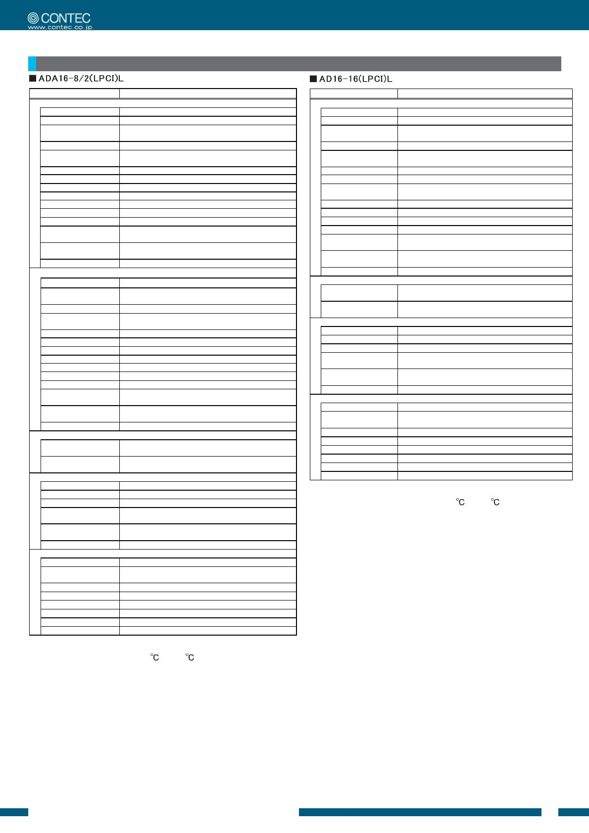
Specifications
Item Specification
Analog input
Isolated specification Un-Isolated
Input type
Single-Ended Input
Number of input
channels
8ch
Input range Bipolar ±10V
Absolute max. input
voltage
±20V
Input impedance 1MΩ or more
Resolution 16bit
Non-Linearity error *1*2 ±5LSB
Conversion speed 10μsec/ch
Buffer memory 1k Word
Conversion start trigger Software / external trigger
Conversion stop trigger Number of sampling times / external trigger/software
External start signal TTL level (Rising or falling edge can be selected by software)
Digital filter (1μsec can be selected by software)
External stop signal TTL level (Rising or falling edge can be selected by software)
Digital filter (1μsec can be selected by software)
External clock signal TTL level (Rising or falling edge can be selected by software)
Analog output
Isolated specification Un-Isolated
Number of output
channels
2ch
Output range Bipolar ±10V
Absolute max. input
currency
±3mA
Output impedance
1Ω or less
Resolution 16bit
Non-Linearity error *1 ±5LSB
Conversion speed
10μsec
Buffer memory 1k Word
Conversion start trigger Software / external trigger
Conversion stop trigger Number of sampling times / external trigger/software
External start signal TTL level (Rising or falling edge can be selected by software)
Digital filter (1μsec can be selected by software)
External stop signal TTL level (Rising or falling edge can be selected by software)
Digital filter (1μsec can be selected by software)
External clock signal TTL level (Rising or falling edge can be selected by software)
Digital I/O
Number of input
channels
4 TTL levels (positive logic)
Number of output
channels
4 TTL levels (positive logic)
Counter
Number of channels 1ch
Counting system Up count
Max. count FFFFFFFFh (Binary data,32bit)
Number of external
inputs
2 TTL levels (Gate/Up)/ch
Gate (High level), Up (Rising edge)
Number of external
outputs
TTL Count match output (positive logic, pulse output)
Response frequency 10MHz (Max.)
Common section
I/O address 64 ports
Interruption level Errors and various factors,
One interrupt request line as INTA
Connector 10250-52A2JL[3M]
Power consumption 5VDC 380mA (Max.)
Operating condition 0 - 50°C, 10 - 90%RH (No condensation)
PCI bus specification 32bit, 33MHz, Universal key shapes supported *3
Dimension (mm) 121.69 (L) x 63.41 (H)
Weight 60g
*1: The non-linearity error means an error of approximately 0.1% occurs
over the maximum range at 0
and 50 ambient temperature.
*2: At the time of the source use of a signal which built in the high-speed
operational amplifier.
*3: This board requires power supply at +5V from an expansion slot (it
does not work on a machine with a +3.3V power supply alone).
Item Specification
Analog input
Isolated specification Un-Isolated
Input type Single-Ended Input
Number of input
channels
16ch
Input range Bipolar ±10V
Absolute max. input
voltage
±20V
Input impedance 1MΩ or more
Resolution 16bit
Non-Linearity error
*1*2
±5LSB
Conversion speed 10μsec/ch
Buffer memory 1k Word
Conversion start trigger Software / external trigger
Conversion stop trigger Number of sampling times / external trigger/software
External start signal TTL level (Rising or falling edge can be selected by software)
Digital filter (1μsec can be selected by software)
External stop signal TTL level (Rising or falling edge can be selected by software)
Digital filter (1μsec can be selected by software)
External clock signal TTL level (Rising or falling edge can be selected by software)
Digital I/O
Number of input
channels
4 TTL levels (positive logic)
Number of output
channels
4 TTL levels (positive logic)
Counter
Number of channels 1ch
Counting system Up count
Max. count FFFFFFFFh (Binary data,32bit)
Number of external
inputs
2 TTL levels (Gate/Up)/ch
Gate (High level), Up (Rising edge)
Number of external
outputs
TTL Count match output (positive logic, pulse output)
Response frequency 10MHz (Max.)
Common section
I/O address 64 ports
Interruption level Errors and various factors,
One interrupt request line as INTA
Connector 10250-52A2JL[3M]
Power consumption 5VDC 260mA (Max.)
Operating condition 0 - 50°C, 10 - 90%RH (No condensation)
PCI bus specification 32bit, 33MHz, Universal key shapes supported *3
Dimension (mm) 121.69 (L) x 63.41 (H)
Weight 60g
*1: The non-linearity error means an error of approximately 0.1%
occurs over the maximum range at 0
and 50 ambient
temperature.
*2: At the time of the source use of a signal which built in the high-
speed operational amplifier.
*3: This board requires power supply at +5V from an expansion slot
(it does not work on a machine with a +3.3V power supply
alone).


