Page is loading ...

BLUETOOTH SYSTEMS®
KIT CONTENTS
Description
QTY
UIB-Door Assembly 1
Module Box 1
Main Harness 1
User Guide Packet 1
Tie Straps 3
Foam Adhesive Pads 4
Scotchlok #558 Connectors 3
Installation Instructions 1
INSTALLATION INSTRUCTIONS
HBCI-DIO-SF-01
REV. DATE: 04/04/2008
A
PPLICABLE MODEL:
2008 Santa Fe
PART NUMBER
U8780 2B000J9 / J4 (NON S/R)
U8781 2B000J9 / J4 (S/R)
Please refer to sections pertaining to SUNROOF and to NON SUNROOF options
Page 1 of 17

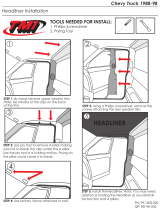
TOOLS REQUIRED
INSTALLATION PROCEDURE
1/16” Drill Bit w/Hex Head 7/32" Drill Bit w/Hex Head 1/2" Drill Bit
#1 Phillips Screwdriver #2 Phillips Screwdriver Cordless Drill Driver Extension
Scissors Plastic Trim Removal Tool 10mm Socket with Ratchet
1" Unibit
Wire Strip/Crimp Tool Safety Goggles Marking Utensil Measuring Scale
Page 2 of 17

1. Disconnect vehicle's negative (-) battery cable.
2. Use #2 phillips screwdriver to remove (2) screws located in overhead console sunglass bin.
3. Pull overhead console down to remove.
4. Disconnect harness and set overhead console aside.
5. Use #2 phillips screw driver to remove sun visor hook base. Repeat this step for both driver and passenger side.
INSTALLATION PROCEDURE
Non-Sunroof
Sunroof
Non-Sunroof
Sunroof
Do NOT
Remove
Headliner
clip will
break if
removed.
Leave in
place.
5
5
4
4
3
2
Page 3 of 17

6. NON-SUNROOF ONLY: (For SUNROOF skip to step 7.)
a. Remove screw cover at left side of driver side sun visor. Use #2 phillips screw driver to remove driver side visor.
Disconnect vanity mirror light.
b. Use plastic trim removal tool to open screw cover on driver side A-pillar trim and remove screw. Remove A-pillar trim.
c. Remove fuse panel door on knee bolster cover. (for wiring information skip to page 12)
INSTALLATION PROCEDURE
a
b
a
c
Page 4 of 17

SUNROOF: NON-SUNROOF:
7. Use plastic trim removal tool to remove sunglass bin door 7. Use plastic trim removal tool to remove sunglass bin
from overhead console. Dispose of spring. door (larger of 2) from overhead console. Dispose of
spring.
8. Harness hole.
a. Use a measuring scale to identify center of harness
hole location on back of overhead console. Mark
center at 53mm (2 1/8 ") from edge of 8. Harness hole.
molded rectangle and 32mm(1 1/4") up from the a. Position measuring scale end on top of screw
bottom of the electronics base. and against plastic bin. Identify center of harness
hole. Mark center 30mm (1 3/16") above screw.
INSTALLATION PROCEDURE
53mm (2 1/8")
30mm
(1 3/16")
a
aa
7
7
Safety Goggles are recommended before moving on to
step 7.
Safety Goggles are recommended before moving on to
step 7.
32mm (1 1/4")
a
Page 5 of 17

SUNROOF: NON SUNROOF:
b. The molding containing the dome lights MUST be b. The molding containing the dome lights MUST be
separated from the O/H console by carefully removing separated from the O/H console by carefully removing
the 4 screws using a #1 Phillips screwdriver. Disengage the 4 screws using a #1 Phillips screwdriver. Disengage
corner clips and remove. Lay overhead console face corner clips and remove. Lay overhead console face
down on clean surface. Drill out 25mm (1") harness down on clean surface. Drill out 25mm (1") harness
hole with 1" Unibit. hole with 1" Unibit.
ALL STYLES:
9. Drill Clip Holes
a. Insert UIB-Door assembly into overhead console, making sure that both pivot pins are properly seated in holes
in the overhead console.
b. Use plastic trim removal tool to close sunglass bin door until door is pushed into the closed position. Rock the
bin door up and down to create vertical marks with both clips. Continue to rock the door up and down 5 more times
without opening the door to establish defined vertical contact lines.
INSTALLATION PROCEDURE
b
a
a
b
b
b
Do not lose the screws or scratch the
surfaces / buttons of the molding.
Disengage corner
clips carefully.
Do not lose the screws or scratch the
surfaces / buttons of the molding.
Disengage corner
clips carefully.
b
Page 6 of 17

SUNROOF: NON SUNROOF:
c. Remove UIB-Door assembly and locate two (2) vertical
marks made by clips. Use clip hole template on
page 17 step 25 to mark hole location center at 13mm
(1/2") from top edge of cavity. c. Remove UIB-Door assembly and locate two (2) vertical
d. Use a measuring scale to mark clearance hole marks made by clips. Use clip hole template on
locations at 44mm (1 3/4") from plastic flange on front page 17 step 25 to mark hole location center at 13mm
of console and 13mm (1/2") down from edge of the OHC (1/2") from top edge of cavity.
flange. Repeat for second hole.
e. Drill pilot hole with 1/16" drill bit with hex head
attached to driver extension. Repeat for second
clearance hole.
INSTALLATION PROCEDURE
Please skip to page 17 step 25 and cut out clip
hole template before proceeding to step 9-c.
c
c
d
e
Please skip to page 17 step 25 and cut out clip
hole template before proceeding to step 9-c.
When marking vertical lines with UIB, the clear lens
may pop off. Retain lens in housing when
measuring with paper template.
When marking vertical lines with UIB, the clear lens
may pop off. Retain lens in housing when measuring
with paper template.
c
c
Page 7 of 17

SUNROOF: NON SUNROOF:
f. Drill same hole with 7/32" drill bit with hex head
attached to driver extension. Repeat for second
clearance hole. d. Drill pilot hole with 1/16" drill bit with hex head
g. Drill same hole with 1/2" Drill bit. Repeat for second attached to driver extension. Drill depth stop can be
clearance hole. marked on drill bit at 3/16" with tape from the cutting
h. Using the clearance hole for easy access, drill pilot edge. Wrap tape around drill bit 10 times. Repeat for
hole with 1/16” drill bit with hex head attached to second hole. Use clip hole template to confirm hole
driver extension. Drill depth stop can be marked on location is accurate, 13mm (1/2") from top edge of
drill bit at 3/16” with tape from the cutting edge. Wrap cavity. Repeat for second hole.
tape around drill bit 10 times. Use clip hole template to
confirm hole location is accurate, 13mm (1/2”) from top
edge of cavity. Repeat for second hole. e. Use cordless drill and 7/32" drill bit with hex head
attached to driver extension to cut full size hole. Drill
depth stop can be marked on drill bit at 3/16" with
tape from the cutting edge. Wrap tape around drill
i. Use cordless drill and 7/32" drill bit with hex head bit 10 times. Repeat for second hole.
attached to driver extension to cut full size hole. Drill
depth stop can be marked on drill bit at 3/16" with tape
from the cutting edge. Wrap tape around drill bit 10
times. Repeat for second hole.
INSTALLATION PROCEDURE
Y
ou must use protective tape on front of sunglass bin
opening to prevent damage from drill.
i
d/e
h
e
h/i
d
e
Protective
Tape
i
Page 8 of 17

SUNROOF: NON-SUNROOF:
j. Replace the dome light molding back into its original f. Replace the dome light molding back into its original
position and secure in place using the 4 screws. position and secure in place using the 4 screws.
10. Insert UIB-Door assembly into overhead console, making
sure that both pivot 10. Insert UIB-Door assembly into overhead console, making
pins are properly sure that both pivot pins are properly seated in holes
seated in holes in the in the overhead console.
overhead console.
11. Mount module box.
a. Use 10mm socket with ratchet to remove (2) bolts
from center metal bracket.
11. Mount module box.
a. Securely connect the wire harness to the module.
INSTALLATION PROCEDURE
Sunroof
a
a
a
10
10
Caution: Use only a hand screwdriver (#1 Phillips)
to tighten the screws. DO NOT use a power
screwdriver as the screws may strip the molding.
Caution: Use only a hand screwdriver (#1 Phillips)
to tighten the screws. DO NOT use a power
screwdriver as the screws may strip the molding.
Page 9 of 17

SUNROOF: NON-SUNROOF:
b. Carefully bend passenger side bracket in
overhead console area to give clearance. b. Peel backing from tape on module box and mount
c. Remove center metal bracket. securely to roof to the rear of center metal bracket
in overhead console opening.
d. Securely connect the
wire harness to the
module.
e. Peel backing from tape on module box and mount
securely to headliner on passenger side. Green
harness connector needs to be towards the
windshield.
INSTALLATION PROCEDURE
Use caution to avoid
sharp metal edges.
Non-Sunroof
e
d
b/c
b
Page 10 of 17

SUNROOF: NON-SUNROOF:
12. Accessory Power Wiring Connections 12. Accessory Power Wiring Connections
a. Cut black-shielded-yellow wire to length, a. Route black-shielded-yellow accessory wire
approximately 200mm (8") long. Remove an through headliner and down A-pillar to fuse panel on
additional 25mm (1") of shielding from end of knee bolster cover.
black-shielded-yellow wire. b. Secure wire to factory harness retainer clips in
A-pillar using tie straps.
c. Wrap foam tape around black-shielded-yellow
b. Disconnect sunroof motor connector. accessory wire and tuck above headliner at top
of A-pillar.
d. Remove 25mm (1") of shielding from the end of
the black-shielded-yellow wire.
c. Clip tape to expose 25mm of wires on the sunroof
motor wire harness.
INSTALLATION PROCEDURE
Keep wire
clear from
all side
curtain
airbag parts
in A-Pillar.
dc
b
a
a
Page 11 of 17

SUNROOF: NON-SUNROOF:
d. Using Scotchlok #558 connect black-shielded-yellow e. Using Scotchlok #558 connect black-shielded-yellow
accessory wire to pin 3 (gray wire) in sunroof motor accessory wire to pin 9 (blue wire w/silver bands) on
(gray) connector R38. the front side of the I/P junction box in D connector.
e. Wrap foam tape around Scotchlok #558. (Remove two connectors to the right of connector D
f. Reconnect grey sunroof motor connector. to gain easy access-See green box in picture E)
f. Wrap foam tape around Scotchlok #558.
INSTALLATION PROCEDURE
Accessory
Power
wrap foam tape
e
d
Accessory
Power
e
D Connector
D Connector
e
f
e
Remove 2 connectors
for easy access to
connector D
Connector
D
Page 12 of 17

SUNROOF: NON-SUNROOF:
13. Constant Power & Ground Wiring Connections 13. Constant Power & Ground Wiring Connections
a. Clip tape to expose 50mm (2") a. Clip tape to expose 50mm (2")
of wires on the overhead of wires on the overhead
console map lamp wire console map lamp wire
harness. harness.
b. Using Scotchlok #558 connect b. Using Scotchlok #558
red power wire to pin 1 (green connect red power wire to
wire) in overhead console map pin 1( green wire) in overhead
lamp white connector R27. console map lamp white
c. Using Scotchlok #558 connector R27.
connect black ground wire c. Using Scotchlok #558
to pin 2( black wire) in connect black ground wire
overhead console map to pin 2 (black wire) in
lamp white connector R27. overhead console map
d. Wrap foam tape around both lamp white connector R27.
Scotchlok #558. d. Wrap foam tape around both
Scotchlok #558.
INSTALLATION PROCEDURE
Expose 50mm
(2") wire
R27
Connector:
Overhead
Console
Map Lamp
Expose
50mm
(2")
wires
a
a
d
d
b/c
b/c
Power
Ground
Power
Ground
Page 13 of 17

SUNROOF: NON-SUNROOF:
14. Routing Wires 14. Routing Wires
a. Secure ALL (3) excess wires with tie straps to a. Secure ONLY red and black wires to main harness
main harness with tie strap. with tie strap.
b. Position remaining harness in front of foam above
headliner and over metal bracket on driver side. b. Position remaining harness above headliner
c. Replace center metal bracket. Carefully bend
and foam on driver side.
passenger side metal bracket back into original
position. Replace bolts to hold center bracket.
INSTALLATION PROCEDURE
b
a
a
c
b
Page 14 of 17

ALL STYLES:
15. Route white connector from main harness through 25mm (1") hole on back side of console.
16. Plug white connector into UIB-Door assembly. Make sure connector locks in place.
17. Reconnect negative (-) battery terminal.
18. Turn the ignition to ON position. The operating buttons on the UIB assembly will illuminate. Allow 5 seconds for
the system to self-check.
19. Push the phone button to activate the system. The blue center bar will illuminate and "BlueConnect Ready"
will be heard. BlueConnect® is now ready for the pairing process and use.
20. Reconnect all wire harness connectors to back of overhead console. Push overhead console into opening and
replace screws.
21. Use plastic trim removal tool to close sunglass bin door until clip locks into place. Ensure door is securely locked
into place (drilled 7/32" holes).
INSTALLATION PROCEDURE
Volume up and
down buttons
Phone button
19
20
16
21
Page 15 of 17

22. Reinstall in reverse order all remaining trim pieces removed during installation.
Sunroof: driver and passenger sun visor hook bases
Non sunroof: A-pillar trim, knee bolster fuse panel door, driver and passenger sun visor hook bases,
and driver sun visor.
23. Check function for all that apply: Map lamps, Dome Lamps, Mirror, Sunroof.
24. Place the user guide packet inside the glove compartment after installation.
INSTALLATION PROCEDURE
23
Note: Maps lamps are controlled by doors
in open/close position.
Page 16 of 17

ALL STYLES:
25.
This step needs to be completed for page 7 step 9-c.
a. Cut out template along solid out side line with scissors. Make sure to follow line and not over cutting.
b. Fold template 90º on dotted line with writing facing up.
c. Lay template onto console with the fold at the top of the inside edge of opening. Distance from dotted line to end of
template will be 13mm (1/2").
d. Mark drill hole location on console making a + on the vertical lines scribed by the two plastic clips.
e. Return to page 7 step 9-c.
INSTALLATION PROCEDURE
26
7/32" Clip Hole Location Template.
26
½
”
Page 17 of 17
/