Page is loading ...

INSTALLATION & OPERATION MANUAL
FOR ECOLAB MODELS:
ES-2000
ES-2000-CS
ES-2000HH
ES-2000HHV
ES-2000-V
ES-2000XSP
ES-2000XSP-PH
ES-4000
ES-4000XSP
ES-4000CDL
ES-4000CDR
www.ecolab.com
ES SERIES DOOR TYPE, CHEMICAL SANITIZING,
SINGLE AND DUAL RACK DISHMACHINES
December 5, 2007
P/N 7610-011-35-10 (Revision O)
Manufactured in the United States by:


REVISION/
PAGE
REVISION
DATE
MADE
BY
APPLICABLE
ECN
DETAILS
I 03-16-04 MAW N/A, 6935
Added both chemical feeder pump rollers. Added Ecolab
#96582747. Converted to the new layout. Added Viton Pump
Seal 5330-002-87-16
J 04-26-04 MAW N/A Added Ecolab numbers.
K 08-31-04 MAW N/A Added ES-2000HH and ES-2000HHV
L 04-13-05 MAW
7228
7107
Added schematic for CD units. Changed reed switch to 05930-
002-36-80 removed switch box weldments. Added common parts
pages. Seperated vacuum breaker and solenoid parts into two
pages. Moved vacuum breaker, solenoid and chemical feeder
pump to common parts section. Changed numbers per Ecolab
request.
M 05-09-05 MAW N/A
Change numbers on pages 33, 34, 61, 66, 67 & 69 per Ecolab
request
N 04-13-06 MAW
7555, 7518
7406, 7415
7260, 7553
Change ES-2000-V Right Side Door from 05700-002-38-34 to
05700-003-13-02. Remove Cotter Pin 05315-011-60-09 and add
Hair Pin 05315-002-15-39. Add Control Box Bracket 05700-002-
90-37 for ES-2000HH. Add new conduit, drip through tube & 1/4”
red, white and blue chemical tubes for the ES-2000HH. Remove
Drip Shield 05700-031-34-80, add Drip trough 05700-031-82-56.
Add false panel kit option. Added ES-2000-V frame 05700-002-
97-85. Added ES-2000-V Accumulator 05700-002-19-05. Added
Pump & Motor Assembly page for ES-2000-CS. Made changes
per Ecolab requests.
O 10-29-07 MAW N/A
Added dimensions on CDL/CDR for handle to table. Added num-
bers for: hood support repair kits, microswitch replacement kit,
cap & brass bonet kit, 1/4” component repair kit, dual strap kit, flat
gasket. Removed one gasket from drain solenoid assemblies.
Updated part numbers per Ecolab requests.
68 12-05-07 MAW N/A Changed drawing and numbers for ES-4000 left door.
i

ii
NOMENCLATURE FOR THE MODELS COVERED IN THIS MANUAL
ES-2000-V
ES = Door type, Chemical Sanitizing
2000 = Single rack dishmachine
4000 = Dual rack dishmachine
CS = Omega design
CDL = Corner model with left hand entry
CDR = Corner model with right hand entry
HH = Higher Hood
HHV = Higher Hood with Vapor Vent
PH = 31” Wide
V = Vapor Vent
XSP = Solid detergent dispensing system
Model:
Serial No.:
Installation Date:
Service Rep. Name:
Phone No.:

SECTION DESCRIPTION PAGE
I. SPECIFICATION INFORMATION
Specifications of the ES-2000 Series Models 2
Specifications of the ES-4000 Series Models 3
Dimensions (ES-2000/ES-2000XSP/ES-2000XSP-PH) 4
Dimensions (ES-2000-CS) 5
Dimensions (ES-2000HH) 6
Dimensions (ES-4000/ES-4000XSP) 7
Dimensions (ES-4000CDL) 8
Dimensions (ES-4000CDR) 9
Table Dimensions 10
II. INSTALLATION & OPERATION INSTRUCTIONS
Installation Instructions 12
Electrical Installation Instructions 13
Operation Instructions 14
Chemical Dispensing Equipment 16
XSP Dispenser Preparation 17
Chemical Set-Up 18
Detergent Set-Up 19
Rinse Feed Set-Up 20
Cam Timer Operation 21
III. PREVENTATIVE MAINTENANCE
Preventative Maintenance 23
IV. TROUBLESHOOTING SECTION 25
V. SERVICE PROCEDURES
Rinse Solenoid Valve Repair Parts Kit 32
Vacuum Breaker Repair Parts Kit 36
VI. PARTS SECTION
Common Parts 39
Chemical Feeder Pump Assembly 42
Solenoid Valve Repair Parts Kits 43
Vacuum Breaker Repair Parts Kits 44
Control Box Assembly 45
Hood Assemblies (ES-2000) 47
Hood Assembly & Associated Parts (ES-2000-CS) 48
Hood Assembly & Associated Parts (ES-2000HH) 49
Hood Assembly (ES-4000) 50
Cantilever Arm Assembly (ES-2000 & ES-4000 Double Bracket Mount) 51
Cantilever Arm/Door Assembly (ES-2000HH) 53
Cantilever Arm Assembly (ES-2000 & ES-4000 Single Bracket Mount) 55
Tub Assembly (ES-2000) 56
Tub Assembly (ES-4000) (Left Front View) 57
Tub Assembly (ES-4000) (Right Front View) 58
Frame & Accumulator Assemblies (ES-2000 & ES-4000) 59
Tub & Frame Assemblies (ES-2000-CS) 60
Incoming Plumbing Assembly (ES-2000 & ES-4000) 61
Incoming Plumbing Assembly & Misc. Parts (ES-2000-CS) 62
Wash Manifold Assembly (ES-2000 & ES-4000) 63
Wash Arm Assembly (ES-2000 & ES-4000) 63
Pump & Motor Assemblies (ES-2000 & ES-4000) 64
Pump & Motor Assemby (ES-2000-CS) 65
TABLE OF CONTENTS
iii

SECTION DESCRIPTION PAGE
Miscellaneous Parts (ES-2000 & ES-4000) 66
Door Assemblies (ES-2000) 67
Door Assemblies (ES-4000) 68
False Panel Option 69
ES-4000CDL Assembly Options 70
ES-4000CDR Assembly Options 72
Vapor Vent Option Assembly (Revision A) 74
Vapor Vent Option Assembly (Revision B) 75
SDI Option (ES-2000HHV) 76
Dispenser Assembly (Front View) 77
Solenoid Mounting Plate Assembly 78
VII. SCHEMATICS
ES-2000/ES-2000-CS (115 Volt, 60 Hz, single phase) 80
ES-2000-V (115 Volt, 60 Hz, single phase) 81
ES-2000XSP (115 Volt, 60 Hz, single phase) 82
ES-4000 (115 Volt, 60 Hz, single phase) 83
ES-4000CDL/ES-4000CDR (115 Volt, 60 Hz, single phase) 84
ES-4000XSP (115 Volt, 60 Hz, single phase) 85
TABLE OF CONTENTS
iv

1
SECTION 1:
SPECIFICATION INFORMATION

ES-2000 & ES-4000 Series Installation/Operation Manual 7610-011-35-10
Issued: 10-29-2007 Revised: N/A
SECTION 1: SPECIFICATION INFORMATION
ES-2000 SERIES SPECIFICATIONS
2
PERFORMANCE/CAPABILITIES
OPERATING CAPACITY (ES-2000’s) (RACKS/HOUR)
RACKS PER HOUR 40
RACKS PER HOUR (OPTION) 48
DISHES PER HOUR 1000
GLASSES PER HOUR 1000
OPERATING CAPACITY (ES-2000HH) (RACKS/HOUR)
RACKS PER HOUR 40
DISHES PER HOUR 1000
GLASSES PER HOUR 1000
OPERATING CAPACITY (ES-2000HHV) (RACKS/HOUR)
RACK PER HOUR 30
DISHES PER HOUR 750
GLASSES PER HOUR 750
OPERATING CAPACITY (ES-2000-V) (RACKS/HOUR)
RACK PER HOUR 30
DISHES PER HOUR 750
GLASSES PER HOUR 750
OPERATING CYCLE (ES-2000’s) (SECONDS)
WASH TIME 40
RINSE TIME 15
TOTAL CYCLE TIME 90
TOTAL CYCLE TIME (OPTION) 72
OPERATING CYCLE (ES-2000HH) (SECONDS)
WASH TIME 44
RINSE TIME 25
TOTAL CYCLE TIME 90
OPERATING CYCLE (ES-2000HHV) (SECONDS)
WASH TIME 44
RINSE TIME 25
TOTAL CYCLE TIME 120
* Total time extended by 30 seconds.
OPERATING CYCLE (ES-2000-V) (SECONDS)
WASH TIME 40
RINSE TIME 15
TOTAL CYCLE TIME 120
*Total time extended by 30 seconds.
TUB CAPACITY (GALLONS)
WASH TUB (MINIMUM) (ES-2000’s) 1.7
WASH TUB (MINIMUM) (ES-2000-CS) 1.2
WASH PUMP CAPACITY
GALLONS PER MINUTE 61
TEMPERATURES
WASH---°F (MINIMUM) 120
WASH---°F (MINIMUM) (ES-2000HH/HHV ONLY) 130
WASH---°F (RECOMMENDED) 140
RINSE---°F (MINIMUM) 120
RINSE---°F (MINIMUM) (ES-2000HH/HHV ONLY) 130
RINSE---°F (RECOMMENDED) 140
ELECTRICAL REQUIREMENTS
WASH PUMP MOTOR HORSEPOWER 3/4
NOTE: Typical Electrical Circuit is based upon (1) 125% of
the full amperage load of the machine and (2) typical
fixed-trip circuit breaker sizes as listed in the NEC 2002
Edition. Local codes may require more stringent protec-
tion than what is displayed here. Always verify with your
electrical service contractor that your circuit protection is
adequate and meets all applicable national and local
codes. These numbers are provided in this manual sim-
ply for reference and may change without notice at any
given time.
TYPICAL
TOTAL ELECTRICAL
VOL
TS HERTZ PHASE AMPS CIRCUIT
ES-2000’s 115 60 1 12.0 15 AMP
WATER REQUIREMENTS
INLET TEMPERATURE (MINIMUM) 120°F
INLET TEMPERATURE (RECOMMENDED) 140°F
INLET TEMPERATURE
ES-2000HH MODELS (RECOMMENDED) 130°F
GALLONS PER HOUR 68
WATER LINE SIZE NPT (MINIMUM) 3/4”
DRAIN LINE SIZE NPT (MINIMUM) 2”
FLOW PRESSURE P.S.I. 20 ±5
MINIMUM CHLORINE REQUIRED (PPM) 50
NOTE: Always refer to the machine data plate for specific
electrical and water requirements. The material provided
on this page is for reference only and may be subject to
change without notice.

ES-2000 & ES-4000 Series Installation/Operation Manual 7610-011-35-10
Issued: 10-29-2007 Revised: N/A
SECTION 1: SPECIFICATION INFORMATION
ES-4000 SERIES SPECIFICATIONS
3
PERFORMANCE/CAPABILITIES
OPERATING CAPACITY (RACKS/HOUR)
RACKS PER HOUR 80
RACKS PER HOUR (OPTION) 96
DISHES PER HOUR 2000
GLASSES PER HOUR 2000
OPERATING CYCLE (SECONDS)
WASH TIME 35
RINSE TIME 20
TOTAL CYCLE TIME 90
TOTAL CYCLE TIME (OPTION) 72
TUB CAPACITY (GALLONS)
WASH TUB (MINIMUM) 3.1
WASH PUMP CAPACITY
GALLONS PER MINUTE 61
TEMPERATURES
WASH---°F (MINIMUM) 120
WASH---°F (RECOMMENDED) 140
RINSE---°F 120
RINSE---°F (RECOMMENDED) 140
ELECTRICAL REQUIREMENTS
(2) WASH PUMP MOTOR HORSEPOWER 3/4 ea.
NOTE: Typical Electrical Circuit is based upon (1) 125% of
the full amperage load of the machine and (2) typical
fixed-trip circuit breaker sizes as listed in the NEC 2002
Edition. Local codes may require more stringent protec-
tion than what is displayed here. Always verify with your
electrical service contractor that your circuit protection is
adequate and meets all applicable national and local
codes. These numbers are provided in this manual sim-
ply for reference and may change without notice at any
given time.
TYPICAL
TOTAL ELECTRICAL
VOL
TS HERTZ PHASE AMPS CIRCUIT
ES-4000’s 115 60 1 23.0 30 AMP
WATER REQUIREMENTS
INLET TEMPERATURE (Minimum) 120°F
INLET TEMPERATURE (Recommended) 140°F
GALLONS PER HOUR 160
WATER LINE SIZE NPT (Minimum) 3/4”
DRAIN LINE SIZE NPT (Minimum) 2”
FLOW PRESSURE P.S.I. 20 ±5
MINIMUM CHLORINE REQUIRED (PPM) 50
NOTE: Always refer to the machine data plate for specific
electrical and water requirements. The material provided
on this page is for reference only and may be subject to
change without notice.

ES-2000 & ES-4000 Series Installation/Operation Manual 7610-011-35-10
Issued: 10-29-2007 Revised: N/A
SECTION 1: SPECIFICATION INFORMATION
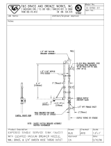
DIMENSIONS ES-2000/ES-2000XSP-PH
4
4” MIN.
ES-2000/XSP 25 1/4”
ES-2000XSP-PH 25 3/4”
TOP VIEW
RACK GUIDES IN STRAIGHT
THROUGH CONFIGURATION
5” MIN
TOP VIEW
RACK GUIDES IN CORNER
CONFIGURATION
12”
6”
24 1/4”
DOORS
19” MAX
CLEARANCE
34”
TABLE HEIGHT
1”
1”
11 1/2”
FRONT
RIGHT SIDE
NOTE: DRAIN IS ON FAR
SIDE OF ACCUMULATOR
4” MIN.
ES-2000/XSP 25 1/4”
ES-2000XSP-PH 30 3/4”
12 1/2”
A
B
D
B
A
C
61”
62”
A- DRAIN CONNECTION 2” NPT
B- ELECTRICAL CONNECTION 3/4” CONDUIT
C- WATER INLET 3/4” NPT
D- XSP DISPENSER
ALL DIMENSION FROM FLOOR ARE ADJUSTABLE +/-
1/2” DUE TO BULLET FEET.
64 1/4”
66 1/4”
77 1/4”

ES-2000 & ES-4000 Series Installation/Operation Manual 7610-011-35-10
Issued: 10-29-2007 Revised: N/A
SECTION 1: SPECIFICATION INFORMATION
DIMENSIONS ES-2000-CS
5
LEGEND
A - WATER INLET (1/2”NPT)
B - ELECTRICAL CONNECTION POINT
C - DRAIN (2” NPT)
D - STANDARD CLEARANCE BETWEEN MACHINE AND
WALL (WITH DISHTABLE) IS 4”.
NOTE: All vertical dimensions are +/- 1/2” due to
adjustable feet.
5” Min.
4 11/16”
25 1/4”
25 1/4”
33 1/4”
Table
10 3/8”
11 3/4” with
Accumulator
Lift Kit
Ecolab No.:
96582202
64 11/16”
67 3/4”
22 1/2”
18”
Opening
62”
24 1/2”
Door
26 1/4”
A
B
C
D

ES-2000 & ES-4000 Series Installation/Operation Manual 7610-011-35-10
Issued: 10-29-2007 Revised: N/A
SECTION 1: SPECIFICATION INFORMATION
DIMENSIONS ES-2000HH
6
4” MIN.
TOP VIEW
RACK GUIDES IN STRAIGHT
THROUGH CONFIGURATION
5” MIN
TOP VIEW
RACK GUIDES IN CORNER
CONFIGURATION
12”
24 1/4”
DOORS
27” MAX
CLEARANCE
34”
TABLE HEIGHT
1”
11 1/2”
FRONT
RIGHT SIDE
NOTE: DRAIN IS ON FAR
SIDE OF ACCUMULATOR
4” MIN.
12 1/2”
A
B
A
C
72”
A- DRAIN CONNECTION 2” NPT
B- ELECTRICAL CONNECTION 3/4” CONDUIT
C- WATER INLET 3/4” NPT
ALL DIMENSION FROM FLOOR ARE ADJUSTABLE +/-
1/2” DUE TO BULLET FEET.
72”
77”
86”
25 1/4”
25 1/4”

ES-2000 & ES-4000 Series Installation/Operation Manual 7610-011-35-10
Issued: 10-29-2007 Revised: N/A
SECTION 1: SPECIFICATION INFORMATION
DIMENSIONS ES-4000/ES-4000XSP
7
TOP VIEW
FRONT VIEW RIGHT SIDE VIEW
A - DRAIN CONNECTION - 2” NPT
B - ELECTRICAL CONNECTION
C - WATER INLET - 3/4” NPT
D - SERVICE DISCONNECT SWITCH
E - XSP DISPENSER
ALL DIMENSION FROM FLOOR ARE ADJUSTABLE +/- 1/2”
DUE TO BULLET FEET.
25 7/8”
1”
60 1/2”
61”
10 1/2”
24 1/2”
DOORS
19” MAX
CLEARANCE
34”
TABLE HEIGHT
32 1/4”
44 1/8”
4” min.
4 3/4”
15 3/4”
C
C
E
B
D
B
A
A
D
D
75 3/4”

ES-2000 & ES-4000 Series Installation/Operation Manual 7610-011-35-10
Issued: 10-29-2007 Revised: N/A
SECTION 1: SPECIFICATION INFORMATION
DIMENSIONS ES-4000CDL
8
20 3/4”
OPENING
4 1/2”
MINIMUM
2 1/2”
1 1/2”
5”
19”
OPENING
20 3/4”
OPENING
2 1/2”
3 1/2”
4”
MINIMUM
2 1/2 “
A - DRAIN-GRAVITY 2” NPT
B - WATER INLET 3/4” NPT
C - ELECTRICAL CONNECTION 3/4”
ALL DIMENSION FROM FLOOR ARE
ADJUSTABLE +/- 1/2” DUE TO BULLET FEET.
32 3/4”
25 3/4”
43 1/2 “
46 1/2”
C
B
A
B
16”
13”
66 1/4”
60 3/4”
12”
34”
77”
14”

ES-2000 & ES-4000 Series Installation/Operation Manual 7610-011-35-10
Issued: 10-29-2007 Revised: N/A
SECTION 1: SPECIFICATION INFORMATION
DIMENSIONS ES-4000CDR
9
19”
OPENING
12 3/8”
2 1/2”
5”
2 1/2”
20 3/4”
OPENING
4 1/2”
MINIMUM
1 1/2”
20 3/4”
OPENING
2 1/2”
4”
MINIMUM
3 1/2”
A.- DRAIN-GRAVITY 2” NPT
B.- WATER INLET 3/4” NPT
C.- ELECTRICAL CONNECTION
ALL DIMENSION FROM FLOOR ARE
ADJUSTABLE +/- 1/2” DUE TO BULLET FEET.
32 3/4”
25 3/4”
43 1/2”
46 1/2”
30 1/2”
16”
C
C
B
B
A
A
77”
60 3/4”
66 1/4”
34”
12”
14”

ES-2000 & ES-4000 Series Installation/Operation Manual 7610-011-35-10
Issued: 10-29-2007 Revised: N/A
SECTION 1: SPECIFICATION INFORMATION
TABLE DIMENSIONS
10
TABLE DIMENSIONS
CORNER INST
ALLATION
T
ABLE DIMENSIONS
CONNECTION TO DISHMACHINE
T
ABLE DIMENSIONS
STRAIGHT THROUGH INSTALLATION
20 1/2”
OPENING
25 1/4”
2 1/4”
4” MIN.
2 1/2”
4”
MIN.
20 1/2”
OPENING
25 1/4”
20 1/2”
3/4”
1 1/2” ROLL
4”
MIN
2 1/2”
25 1/4”
20 1/2”
OPENING
25 1/4” ES-2000
30 3/4” XSP-PH
44” ES-4000

11
SECTION 2:
INSTALLATION/OPERATION
INSTRUCTIONS

VISUAL INSPECTION: Before installing the unit, check the container and machine for damage. Adamaged container is an indi-
cator that there may be some damage to the machine. If there is damage to both the container and machine, do not throw away
the container. The dishmachine has been inspected and packed at the factory and is expected to arrive to you in new, undam-
aged condition. However, rough handling by carriers or others may result in there being damage to the unit while in transit. If
such a situation occurs, do not return the unit to Ecolab; instead, contact the carrier and ask them to send a representative to
the site to inspect the damage to the unit and to complete an inspection report. You must contact the carrier within 48 hours of
receiving the machine.
UNPACKING THE DISHMACHINE: Once the machine has been removed from the container, ensure that there are no miss-
ing parts from the machine. This may not be obvious at first. If it is discovered that an item is miss-
ing, contact Ecolab immediately to have the missing item shipped to you.
LEVEL THE DISHMACHINE: The dishmachine is designed to operate while being level. This is
important to prevent any damage to the machine during operation and to ensure the best results
when washing ware. The unit comes with adjustable bullet feet, which can be turned using a pair of
channel locks or by hand if the unit can be raised safely. Ensure that the unit is level from side to
side and from front to back before making any connections.
PLUMBING THE DISHMACHINE: All plumbing connections must comply with all applicable local, state, and national plumb-
ing codes. The plumber is responsible for ensuring that the incoming water line is thoroughly flushed prior to connecting it to
any component of the dishmachine. It is necessary to remove all foreign debris from the water line that may potentially get
trapped in the valves or cause an obstruction.
CONNECTING THE DRAIN LINE: The drains for the ES-2000/ES-4000 dishmachines are gravity discharge. All piping from
the 2” MNPT connection on the waste accumulator must be pitched (1/4” per foot) to the floor or sink drain. All piping from the
machine to the drain must be a minimum 2” NPT and shall not be reduced. There must also be an air gap between the machine
drain line and the floor sink or drain. If a grease trap is required by code, it should have a flow capacity of 5 gallons per minute.
WATER SUPPLY CONNECTION: Ensure that you have read the section entitled “PLUMBING
THE DISHMACHINE” above before proceeding. Install the water supply line (3/4” pipe size min-
imum) to the dishmachine line strainer using copper pipe. It is recommended that a water shut-
off valve be installed in the water line between the main supply and the machine to allow access
for service. The water supply line is to be capable of 20±5 PSI “flow” pressure at the recom-
mended temperature indicated on the data plate.
NOTE: The optional Vapor Vent system must be connected to the COLD water line.
In areas where the water pressure fluctuates or is greater than the recommended pressure, it is suggested that a water pres-
sure regulator be installed.
Do not confuse static pressure with flow pressure. Static pressure is the line pressure in a “no flow” condition (all valves and
services are closed). Flow pressure is the pressure in the fill line when the fill valve is opened during the cycle.
It is also recommended that a shock absorber (not supplied) be installed in the incoming water line. This prevents line hammer
(hydraulic shock), induced by the solenoid valve as it operates, from causing damage to the equipment.
PLUMBING CHECK: Slowly turn on the water supply to the machine after the incoming fill line and the drain line have been
installed. Check for any leaks and repair as required. All leaks must be repaired prior to placing the machine in operation.
ES-2000 & ES-4000 Series Installation/Operation Manual 7610-011-35-10
Issued: 10-29-2007 Revised: N/A
SECTION 2: INSTALLATION/OPERATION INSTRUCTIONS
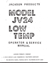
INSTALLATION INSTRUCTIONS
12
Frame with Adjustable Foot
Raise
Lower
Incoming Plumbing Connection

ELECTRICAL POWER CONNECTION: Electrical and grounding connections must comply with the applicable portions of the
National Electrical Code ANSI/NFPA 70 (latest edition) and/or other electrical codes.
Disconnect electrical power supply and place a tag at the disconnect switch to indi-
cate that you are working on the circuit.
The dishmachine data plate is located on the right side and to the front of the
machine. Refer to the data plate for machine operating requirements, machine volt-
age, total amperage load and serial number.
To install the incoming power lines, unlock the control box. Install 3/4” conduit into
the pre-punched holes in the back of the control box. Route power wires and con-
nect to power block and grounding lug. Install the service wires (L1 & L2) to the
appropriate terminals as they are marked on the terminal block. Install the ground-
ing wire into the lug provided.
It is recommended that “DE-OX” or another similar anti-oxidation agent be used on
all power connections.
VOLTAGE CHECK: Ensure that the power switch is in the OFF position and apply power to the dishmachine. Check the incom-
ing power at the terminal block and ensure it corresponds to the voltage listed on the data plate. If not, contact a qualified ser-
vice agency to examine the problem. Do not run the dishmachine if the voltage is too high or too low. Shut off the service break-
er and mark it as being for the dishmachine. Advise all proper personnel of any problems and of the location of the service
breaker. Replace the control box cover and tighten down the screws.
ES-2000 & ES-4000 Series Installation/Operation Manual 7610-011-35-10
Issued: 10-29-2007 Revised: N/A
SECTION 2: INSTALLATION/OPERATION INSTRUCTIONS
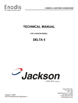
ELECTRICAL INSTALLATION INSTRUCTIONS
13
Ground Lug
Power Block

PREPARATION: Before proceeding with start-up verify the following:
A. Sump strainer is in place.
B. Drain stopper is installed.
C. Check that the wash arms are securely screwed into the stationary bases and rotate freely. Also check that the end plugs
are securely screwed into the ends of all wash arms.
POWER UP: To energize electrically, proceed as follows:
A. Turn on electrical power supply at the circuit breaker.
B. Check voltage at incoming terminals L1& L2. The voltage measured at these points should match data plate voltage.
C. If voltages are in required range, close the control box cover.
TO FILL WASH TUB: To Fill Wash Tub depress the “On/Off/Fill” rocker switch to the “Fill” position and hold until you see water
draining out from the bottom of the machine. Open door for 3 seconds and close, this will start machine cycle. Allow machine
to complete one cycle, and then check for proper water level.
Note: Water must be in the sump while the machine is running to avoid running the pump dry and causing damage to the
pump seal.
If the water level is not at the level noted above it will require adjustment. Check to ensure that the recommended water pres-
sure is being supplied to the machine (20 ±5 PSI is required). If the water pressure is correct then the fill valve cam will need
adjustment. Use the following steps to adjust the cam.
A. Turn power off at the machine circuit breaker.
B. Open control box cover
C. Locate the timer fill valve cam (Cam 4 from the timer motor)
D. Locate the spanner wrench taped to the electrical panel. The spanner wrench is used to adjust the cam.
E. To increase the water level, open the notch of the adjustable cam. To decrease the water level, close the notch. Care must
be taken that the set point does not extend into the home position of the timer. Do not move the side of the cam that starts the
fill; this will change the sequence of cycle operation.
F. With the door closed turn the power circuit breaker on. Open and close the door to run a cycle, then check the water level.
Adjust as necessary then close the control box cover.
Refer to page 21 for adjustment to the cam timer.
NOTE: The machine must run a complete cycle to drain and fill. If the machine is not allowed to drain, the water will build up
inside the tub. After the initial fill, the rinse water for the current cycle will become the wash water for the next cycle.
The dishmachine is now ready to proceed with the washing of dishes.
VAPOR VENT OPTION: If the dishmachine is fitted with the optional vapor vent system, it will be shipped from the factory with
the vent option installed. Run several cycles to confirm that the vapor vent is functioning properly. At the end of the venting
sequence, there should be only a small amount of vapor released from the machine when the door interlock retracts and the
machine doors are opened.
ES-2000 & ES-4000 Series Installation/Operation Manual 7610-011-35-10
Issued: 10-29-2007 Revised: N/A
SECTION 2: INSTALLATION/OPERATION INSTRUCTIONS
OPERATING INSTRUCTIONS
14
/