Ecolab ES-2000HT INTL Installation & Operation Manual
- Category
- Dishwashers
- Type
- Installation & Operation Manual

INSTALLATION & OPERATION MANUAL
FOR ECOLAB MODELS:
ES-2000HT INTL
www.ecolab.com
An
Company
HOT WATER SANITIZING UPRIGHT DOOR DISHMACHINE
July 10, 2006
P/N 7610-003-24-90 (Revision A)
Manufactured in the United States by:


REVISION
REVISION
DATE
MADE
BY
APPLICABLE
ECN
DETAILS
A 07-10-06 MAW 7820 Release to production.
i

ii
NOMENCLATURE FOR THE MODELS COVERED IN THIS MANUAL
ES-2000HT INTL
ES-2000HT - Hot water sanitizing, electrically-heated export model dishmachine
Model:
Serial No.:
Installation Date:
Service Rep. Name:
Phone No.:

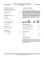
SECTION DESCRIPTION PAGE
I. SPECIFICATION INFORMATION
Specifications 2
Dimensions 3
Table Dimensions 4
II. INSTALLATION & OPERATION INSTRUCTIONS
Installation Instructions 6
Electrical Installation Instructions 7
Operation Instructions 8
Timer Programming Instructions 10
III. PREVENTATIVE MAINTENANCE
Preventative Maintenance 13
IV. TROUBLESHOOTING SECTION
Common Problems 15
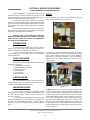
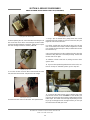
V. SERVICE PROCEDURES
Rinse Solenoid Valve Repair Parts Kit 19
Vacuum Breaker Repair Parts Kit 23
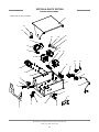
VI. PARTS SECTION
Standard Parts 26
Chemical Feeder Pump Assembly 39
Solenoid Valve Repair Kit 30
Vacuum Breaker Repair Kit 31
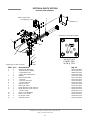
Control Box Assembly 32
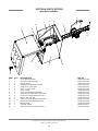
Hood Assembly 34
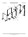
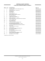
Frame & Tub Assemblies 35
Motor & Pump Assembly 36
Booster Tank Assembly 37
Drain Motor Assembly 38
Cantilever Arm/Door Assemblies 39
Incoming Plumbing Assembly 41
Outlet Plumbing Assembly 42
Wash/Rinse Arms/Manifold Assemblies 43
Inner Tub Components 45
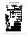
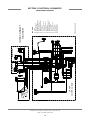
VII. ELECTRICAL SCHEMATICS
380 Volt, 50 Hertz, Three Phase 47
Interconnect Diagram 48
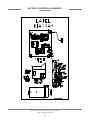
Label Diagram 49
TABLE OF CONTENTS
iii

1
SECTION 1:
SPECIFICATION INFORMATION

PERFORMANCE/CAPABILITIES
OPERATING CAPACITY (RACKS/HOUR)
RACKS PER HOUR (NSF RATED) 55
DISHES PER HOUR 1375
GLASSES PER HOUR 1375
OPERATING CYCLE (SECONDS)
WASH TIME 41
RINSE TIME 11
TOTAL CYCLE TIME 62
TANK CAPACITY (GALLONS)
WASH TANK (MINIMUM) 1.25
BOOSTER TANK 6
WASH PUMP CAPACITY
GALLONS PER MINUTE 55
TEMPERATURES
WASH---°F (MINIMUM) 150
RINSE---°F (MINIMUM) 180
ELECTRICAL REQUIREMENTS
WASH PUMP MOTOR HORSEPOWER 3/4
NOTE: Typical Electrical Circuit is based upon (1) 125% of
the full amperage load of the machine and (2) typical
fixed-trip circuit breaker sizes as listed in the NEC 2002
Edition. Local codes may require more stringent protec-
tion than what is displayed here. Always verify with your
electrical service contractor that your circuit protection is
adequate and meets all applicable national and local
codes. These numbers are provided in this manual sim-
ply for reference and may change without notice at any
given time.
RINSE TYPICAL
HEATER TOTAL ELECTRICAL
VOLTS PH HZ RATINGS AMPS CIRCUIT
380 3 50 14KW@230V WYE 23 30 AMP
WATER REQUIREMENTS
INLET TEMPERATURE (Minimum) 110°F
WATER LINE SIZE NPT (Minimum) 1/2”
DRAIN LINE SIZE NPT (Minimum) 2”
FLOW PRESSURE P.S.I. 20A5
FRAME DIMENSIONS
WIDTH 25 1/4”
DEPTH 25 1/4”
HEIGHT 66 1/4”
STANDARD TABLE HEIGHT 34”
MAXIMUM CLEARANCE 19”
NOTE: Always refer to the machine data plate for specific
electrical and water requirements. The material provided
on this page is for reference only and may be subject to
change without notice.
ES-2000HT INTL Installation & Operation Manual 7610-003-24-90
Issued: 07-10-2006 Revised: N/A
SECTION 1: SPECIFICATION INFORMATION
SPECIFICATIONS
2

ES-2000HT INTL Installation & Operation Manual 7610-003-24-90
Issued: 07-10-2006 Revised: N/A
SECTION 1: SPECIFICATION INFORMATION
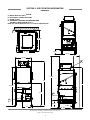
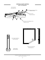
DIMENSIONS
3
LEGEND
A- WATER INLET (1/2” NPT)
B- ELECTRICAL CONNECTION POINT
C- DRAIN (2” NPT)
D- STANDARD CLEARANCE BETWEEN MACHINE
AND WALL (WITH DISHTABLE) IS 4”.
NOTE: All vertical dimensions are +/- 1/2” due to adjustable feet.
8 3/8”
25 1/4”
24 7/8”
56 5/8”
67”
34”
15”
A
9 3/4”
6 3/8”
C
B
D
32 1/4”
22 1/2”
75 1/4”
29 3/4”
61”

ES-2000HT INTL Installation & Operation Manual 7610-003-24-90
Issued: 07-10-2006 Revised: N/A
SECTION 1: SPECIFICATION INFORMATION
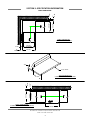
TABLE DIMENSIONS
4
TABLE DIMENSIONS
CORNER INSTALLATION
TABLE DIMENSIONS
CONNECTION TO DISHMACHINE
TABLE DIMENSIONS
STRAIGHT THROUGH INSTALLATION
20 1/2”
OPENING
25 1/4”
2 1/4”
4”
MIN.
2 1/2”
4”
MIN.
20 1/2”
OPENING
25 1/4”
20 1/2”
3/4”
1 1/2” ROLL
4”
MIN
2 1/2”
25 1/4”
20 1/2”
OPENING
25 1/4”

5
SECTION 2:
INSTALLATION/OPERATION
INSTRUCTIONS

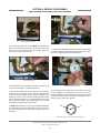
VISUAL INSPECTION: Before installing the unit, check the container and machine for damage. A damaged container indicates
that there may be some damage to the machine. If there is damage to both the container and machine, do not throw away the
container. The dishmachine has been inspected and packed at the factory and is expected to arrive to you in new, undamaged
condition. However, rough handling by carriers or others may damage the unit while in transit. If this situation occurs, do not
return the unit to Ecolab; contact the carrier and ask them to inspect the damage to the unit and to complete an inspection
report. You must contact the carrier within 48 hours of receiving the machine.
UNPACKING THE DISHMACHINE: Once the machine has been removed from the container, ensure that there are no miss-
ing parts from the machine. This may not be obvious at first. If it is discovered that an item is missing, contact your Ecolab rep-
resentative immediately to have the missing item shipped to you.
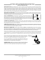
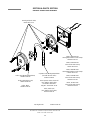
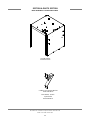
LEVEL THE DISHMACHINE: The dishmachine is designed to operate while being level. This is
important to prevent any damage to the machine during operation and to ensure the best results
when washing ware. The unit comes with adjustable bullet feet, which can be turned using a pair
of channel locks or by hand if the unit can be raised safely. Ensure that the unit is level from side
to side and from front to back before making any connections.
PLUMBING THE DISHMACHINE: All plumbing connections must comply with all applicable local, state, and national plumb-
ing codes. The plumber is responsible for flushing the incoming water line prior to connecting it to remove all foreign debris that
may get trapped in the valves or cause an obstruction.
CONNECTING THE DRAIN LINE: The ES-2000HT drain requires a minimum of 2” NPT piping that is pitched at least 1/4” per
foot. There must also be an air gap between the machine drain line and the floor sink or drain. If a grease trap is required by
code, it should have a flow capacity of 5 gallons per minute.
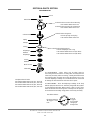
WATER SUPPLY CONNECTION: Read the section entitled “PLUMBING THE DISHMACHINE” above before proceeding.
Install the water supply line (1/2” pipe size minimum) to the dishmachine line strainer using copper pipe. It is recommended
that a water shut-off valve be installed between the main supply and the machine to allow access for service. The water sup-
ply line must be capable of 20A5 PSI “flow” pressure at the recommended temperature indicated on the data plate.
A water pressure regulating valve (PRV) is included as a standard item on the ES-2000HT. The pressure of the incoming water
should be adjusted to 20A5 PSI (flow) by turning the adjustment screw on the top of the PRV (clockwise to increase pressure,
counter-clockwise to decrease pressure). This adjustment must only be done while the incoming water fill solenoid valve is
open.
Do not confuse static pressure with flow pressure. Static pressure is the line pres-
sure in a “no flow” condition (all valves and services are closed). Flow pressure
is the pressure in the fill line when the fill valve is opened during the cycle.
It is also recommended that a shock absorber (not supplied) be installed in the
incoming water line. This prevents line hammer (hydraulic shock), induced by the
solenoid valve, from causing damage to the equipment.
PLUMBING CHECK: Slowly turn on the water supply to the machine after con-
necting the incoming fill line and the drain line. Check for leaks and repair as
required. Leaks must be repaired prior to placing the machine in operation.
ES-2000HT INTL Installation & Operation Manual 7610-003-24-90
Issued: 07-10-2006 Revised: N/A
SECTION 2: INSTALLATION/OPERATION INSTRUCTIONS
INSTALLATION INSTRUCTIONS
6
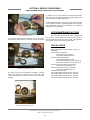
Frame with Adjustable Foot
Adjusting screw
Locking nut
Incoming Plumbing Connection
Raise
Lower

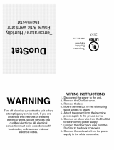
ELECTRICAL POWER CONNECTION: Electrical and grounding connections must comply with the applicable portions of the
National Electrical Code ANSI/NFPA 70 (latest edition) and/or other electrical codes.
Disconnect electrical power supply and lockout the disconnect switch to indicate that you are working on the circuit.
The dishmachine data plate is located on the right side front of the machine. Refer to the data plate machine voltage, total
amperage load and serial number.
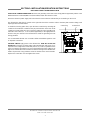
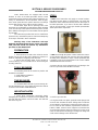
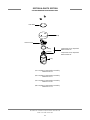
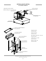
To install the incoming power lines, open the lower control box by removing the
control box lid. Install 3/4” conduit into the pre-punched holes in the back of the
control box. Route power wires and connect to power block and grounding lug.
Install the service wires (L1, L2 & L3 (Where applicable)) to the appropriate ter-
minals as they are marked on the terminal block. Install the grounding wire into
the lug provided.
It is recommended that “DE-OX” or another similar anti-oxidation agent be used
on all power connections.
VOLTAGE CHECK: Apply power to the dishmachine. Note: Do not turn the
machine on. Check the incoming power at the terminal block and ensure it cor-
responds to the voltage listed on the data plate. If not, contact a qualified service
agency to examine the problem. Do not run the dishmachine if the voltage is too
high or low. Shut off the service breaker and mark it as being for the dishmachine.
Advise all personnel of any problems and of the location of the service breaker.
Replace the control box cover and tighten the screws.
ES-2000HT INTL Installation & Operation Manual 7610-003-24-90
Issued: 07-10-2006 Revised: N/A
SECTION 2: INSTALLATION/OPERATION INSTRUCTIONS
ELECTRICAL INSTALLATION INSTRUCTIONS
7
Incoming Power Connection
Power BlockGround Lug

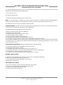
OPERATIONAL START-UP & CHECK: Before proceeding with start-up, verify the following:
1. Open the doors and verify that the pump intake strainer is correctly installed in the sump.
2. Check that the upper and lower rinse arms are securely screwed into their receptacles.
3. Check that the plugs are securely screwed into the ends of both wash arms and the rinse arms.
4. Check that the wash arms are securely screwed into the stationary bases and that they rotate freely.
5. Verify that the drain stopper is correctly installed at the drain seat.
QUICK START GUIDE: After the initial installation of the machine:
1. Insert chemical feeder pump stiffeners into appropriate containers.
2. Turn on machine.
POWER UP: To energize electrically, proceed as follows:
A. Turn on electrical power supply at the circuit breaker.
B. Check voltage at incoming terminals L1, L2 & L3. The voltage measured at these points should match data plate voltage.
C. If voltages are in required range, close the control box cover.
3. Before enabling the booster heater, the booster heater tank must first be filled with water.
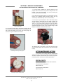
TO FILL BOOSTER HEATER WITH WATER:
4. Press and hold the manual fill switch on the right side of the control box until you hear water being sprayed from the rinse
arms, indicating that the rinse tank is filled with water.
TO ENABLE THE BOOSTER HEATER:
5. Connect the orange/white wire in the control box from the heater contactor to the orange/white wire on terminal board 2.
NOTE: Ensure the orange/white wires at the heater contactor are connected properly. They have been purposely
disconnected at the factory to avoid damage to the heater element when there is no water in the booster tank.
6. Run a few machine cycles to verify the correct operation of the machine.
Check for water leaks.
Verify that the rinse temperature is between 180°F and 195°F for the entire rinse sequence. If it is not, before adjusting the rinse
thermostat, verify that the incoming water temperature is 110°F minimum and that the incoming water flow pressure is 20A5 psi
(measured during the rinse sequence). Adjust the pressure regulating valve as necessary to achieve 20A5 psi.
TO FILL WASH TUB: To Fill Wash Tub depress the “On -Off” switch to the “On” position. Depress and hold Fill Switch until you
see water draining out from the bottom of the machine. Open door for 3 seconds and close, this will start machine cycle. Allow
machine to complete one cycle, and then check for proper water level.
Note: Water must be in the sump while the machine is running to avoid running the pump dry and causing damage to the pump
seal.
If the water level is not at the level noted above it will require adjustment. Check to ensure that the recommended water pres-
ES-2000HT INTL Installation & Operation Manual 7610-003-24-90
Issued: 07-10-2006 Revised: N/A
SECTION 2: INSTALLATION/OPERATION INSTRUCTIONS
OPERATING INSTRUCTIONS
8

sure is being supplied to the machine (20 ±5 PSI is required). If the water pressure is correct then the fill valve control will need
adjustment. Use the following steps to adjust the timer.
A. Open control box cover
B. Locate the electronic timer.
C. Refer to the next page for adjustment to the electronic timer.
NOTE: The machine must run a complete cycle to drain and fill. If the machine is not allowed to drain, the water will build up
inside the tub. After the initial fill, the rinse water for the current cycle will become the wash water for the next cycle.
The dishmachine is now ready to proceed with the washing of dishes.
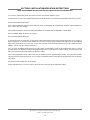
PREPARING DISHES: Preparation of the ware will help ensure good results and less re-washes. If not done properly the dish-
es will not be clean and will reduce the efficiency of the dishmachine.
The following steps should be followed to ensure good results:
A. Remove all scraps and gross soil into a garbage can.
B. Separate and pre-soak silverware.
C. Separate and pre-soak the egg and casserole dishes.
D. Scrape all ware with a brush or spatula.
E. Flush cups, bowls and glasses with running water.
F. Prewash dishware by soaking or spraying with a pre-rinse hose.
G. Place dishes and cups in dish rack. Cups should be upside down (so they don’t hold water).
H. Place glasses and flatware in their respective racks. Scatter flatware loosely in rack. Glasses should be placed upside down
in a properly sized rack. For optimal results, flatware should be washed twice, the first being horizontal, the second in a special
rack to hold flatware vertical.
DAILY MACHINE PREPARATION: Before proceeding with start-up, verify the following:
A. Open door and verify that the sump strainer is in place in the sump.
B. Verify that the drain stopper is in position.
C. Check that the plugs are securely screwed into the ends of all wash arms.
D. Check that the wash arms are securely screwed into the stationary bases and rotate freely.
E. Check levels in all chemical containers and replace if empty.
F. For initial fill, close doors then depress the “FILL” switch to the “FILL” position.
WASHING A RACK OF WARE:
A. Open doors, place a full rack into the machine, and close doors. Unit will start automatically.
B. After cycle is completed open doors and remove rack.
C. Place another full rack into the dishmachine, and close doors.
D. Dishmachine will repeat cycle.
SHUT DOWN AND CLEANING:
A. At the end of mealtime, move the “OFF/ON” switch to the “OFF” position.
B. Open doors and manually remove drain stopper to drain the unit.
C. Remove and clean upper and lower wash arms.
D. Remove and clean the sump strainer.
ES-2000HT INTL Installation & Operation Manual 7610-003-24-90
Issued: 07-10-2006 Revised: N/A
SECTION 2: INSTALLATION/OPERATION INSTRUCTIONS
OPERATING INSTRUCTIONS (CONTINUED)
9

ES-2000HT INTL Installation & Operation Manual 7610-003-24-90
Issued: 07-10-2006 Revised: N/A
10
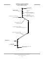
To access the programming mode, the machine must be ON, and idle (between cycles).
On the timer board, press and hold both the MOVE and ENTER buttons on the timer board simultaneously for two seconds.
The PROGRAM light will illumniate.
Once in the programming mode, the MOVE button is used to scroll between the programming categories and the ENTER but-
ton is used to select the category.
Press the MOVE button to move the blinking light between FILL, RINSE AID, DETERGENT or SANITIZER.
Press the ENTER button for the chosen category.
The PROGRAM light will illuminate.
To change the value of a parameter, use the MOVE button to illuminate the light next to the time option (time is in seconds). In
the time categories, each second in use will light up. To deselect the option, press ENTER and the light will go off, press ENTER
again and it will illuminate. Once you have set your time category, press the MOVE button to the ACCEPT option and press
ENTER. This will save the changed parameters.
Once you press the ENTER button when the ACCEPT option is illuminated, you will exit the programming mode. To change
any other values, you will have to return to the programming mode. To revert back to a previous setting, you must return to that
option and change the parameter back to the previous setting.
Once in the programming mode, if there have been no keypad inputs for approximately 2 minutes, the system will automati-
cally exit out of the programming mode. Any changes to parameters will be saved when the programming mode is automati-
cally exited.
The wash and drain settings are not adjustable.
All time adjustments are in seconds. Refer to the chart on the next page for the adjustable outputs.
SECTION 2: INSTALLATION/OPERATION INSTRUCTIONS
TIMER PROGRAMMING INSTRUCTIONS FOR (FOR INSTALLATION TECHNICIAN ONLY)

ES-2000HT INTL Installation & Operation Manual 7610-003-24-90
Issued: 07-10-2006 Revised: N/A
11
SECTION 2: INSTALLATION/OPERATION INSTRUCTIONS
TIMER PROGRAMMING INSTRUCTIONS FOR (FOR INSTALLATION TECHNICIAN ONLY)
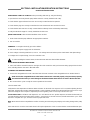
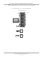
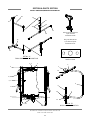
Time in seconds.
FILL
DETERGENT
RINSE AID
Timer Programming Board
Please note that options A, B, C, G and H are not adjustable outputs.

12
SECTION 3:
PREVENTATIVE MAINTENANCE

The dishmachines covered in this manual are designed to operate with a minimum of interaction with the operator. However,
this does not mean that some items will not wear out in time.
There are many things that operators can do to prevent catastrophic damage to the dishmachine. One of the major causes of
component failure has to do with prescrapping procedures. A dishmachine is not a garbage disposal; any large pieces of mate-
rial that are put into the machine shall remain in the machine until they are either broken up (after spreading out on your ware!)
or physically removed. Strainers are installed to help catch debris, but they do no good if they are clogged. Have operators reg-
ularly inspect the pan strainers to ensure (1) that they are free of soil and debris and (2) they are laying flat in the tub.
When cleaning out strainers, do NOT beat them on waste cans. The strainers are made of metal and can be forgiving; but once
severe damage is done, it is next to impossible for the strainer to work in the way it was designed to. Wipe out strainers with
a rag and rinse under a faucet if necessary. For stubborn debris, a toothpick should be able to dislodge any obstructions from
the perforations. Always ensure that strainers are placed back in the machine before operation and that they lay flat in the tub.
You may wish to contact your Ecolab representative in order to learn more about how your water hardness will effect the per-
formance of your machine. Hard water makes dishmachines work harder and decreases efficiency.
Again, it is important to remind operators that trying to perform corrective maintenance on the dishmachine could lead to larg-
er problems or even cause harm to the operator. If a problem is discovered; secure the dishmachine using proper shut down
procedures as listed in this manual and contact your Ecolab representative.
Some problems, however, may have nothing to do with the machine itself and no amount of preventative maintenance is going
to help. A common problem has to do with temperatures being too low. Verify that the water temperatures coming to your dish-
machine match the requirements listed on the machine data plate. There can be a variety of reasons why your water temper-
ature could be too low and you should discuss it with your Ecolab representative to determine what can be done.
By following the operating and cleaning instructions in this manual, you should get the most efficient results from your machine.
As a reminder, here are some steps to take to ensure that you are using the dishmachine the way it was designed to work:
1. Ensure that the water temperatures match those listed on the machine data plate.
2. Ensure that all strainers are in place before operating the machine.
3. Ensure that all wash and/or rinse arms are secure in the machine before operating.
4. Ensure that drains are closed/sealed before operating.
5. Remove as much soil from dishes by hand as possible before loading into racks.
6. Do not overfill racks.
7. Ensure that glasses are placed upside down in the rack.
8. Ensure that all chemicals being injected to machine have been verified as being at the correct concentrations.
9. Clean out the machine at the end of every workday as per the instructions in the manual.
10. Always contact your Ecolab representative whenever a serious problem arises.
11. Follow all safety procedures, whether listed in this manual or put forth by local, state or national codes/regulations.
ES-2000HT INTL Installation & Operation Manual 7610-003-24-90
Issued: 07-10-2006 Revised: N/A
SECTION 3: PREVENTATIVE MAINTENANCE
PREVENTATIVE MAINTENANCE
13

14
SECTION 4:
TROUBLESHOOTING

This trouble-shooting guide will help identify failed components. Before replacing a component that has been identi-
fied as faulty, double-check the wiring to and from the component, to ensure that the problem is not first caused by a
loose or open connection.
Inspection, testing and repair of electrical equipment should be performed only by qualified service personnel. Certain proce-
dures in this section require electrical tests or measurements while power is applied to the machine. Exercise extreme caution
at all times. If test points are not easily accessible, disconnect power, attach test equipment and reapply power to test. When
replacing electrical parts, disconnect power at source circuit breaker.
Problem: Machine will not turn on.
1. No power to dishmachine.
a. Check that service disconnect supplying power to the machine is ON.
b. Measure voltage at terminal block in lower control box. If no voltage exists, or the voltage does not match the voltage indi-
cated on the machine's data plate, seek the assistance of a qualified electrician.
Rinse booster tank must be filled with water before the heater is enabled to prevent damage to the heater element.
Problem: The temperature of the rinse water is too low, or the wash is being extended too often (when this feature is
enabled).
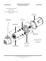
1. Incoming water pressure and/or temperature are not within required specifications. Check the temperature of the incoming
water. It must be 110°F minimum. Check the flow pressure of the incoming water (observe the indication on the pressure
gauge on the incoming water line when the incoming water solenoid valve is open). The pressure must be between 15 and 25
psi.
2. Rinse tank temperature setting is too low, or heater element has been disabled. It should typically be set at approximately
185°F, depending on the operating parameters at the particular installation. Confirm that the heater element has been enabled.
3. The rinse tank heating element is faulty. Using a clamp-type amp probe, measure the amperage through each coil of the
heater element wires. The amperage should be approximately equal through each coil. If not, replace the heater element. An
alternate method of checking the heater element is to first disconnect power to the machine, and then disconnect all wires at
the heater element. Measure the resistance of each coil of the heater element. The resistance measurements should be
approximately equal through each coil.
Problem: Machine will not fill or rinse.
1. The incoming water line is blocked, preventing water from entering the machine. Check and, if necessary, clean the Y-strain-
er on the incoming water line.
2. The incoming water solenoid valve is faulty. Replace solenoid valve.
Problem: Wash pump motor will not run.
1. The wash pump motor is faulty. If you hear the contactor engage when you try to manually run the pump and the pump
does not run, the pump motor is faulty and must be replaced. The motor contains integral thermal overload protection devices.
If the motor becomes hot from excessive loads, these devices open the electrical circuit within the motor and prevent the motor
from running. Before replacing the motor, allow it to cool so that the overload devices can reset themselves, and then re-test
the motor. If the motor still does not run, replace the motor.
Problem: Machine runs with the doors open.
1. Door switch is faulty. Disconnect the door switch leads and check for continuity between the two leads when the doors are
open. If continuity, replace door switch.
Problem: Machine will not drain. Drain mechanism does not move up or down.
1. Loose wire connection. Verify that all wire connections are tight.
2. Drain hole may be obstructed. Remove the obstruction.
3. Drain rod bent or binding. Repair the rod, or replace as necessary.
ES-2000HT INTL Installation & Operation Manual 7610-003-24-90
Issued: 07-10-2006 Revised: N/A
SECTION 4: TROUBLESHOOTING
COMMON PROBLEMS
15
Page is loading ...
Page is loading ...
Page is loading ...
Page is loading ...
Page is loading ...
Page is loading ...
Page is loading ...
Page is loading ...
Page is loading ...
Page is loading ...
Page is loading ...
Page is loading ...
Page is loading ...
Page is loading ...
Page is loading ...
Page is loading ...
Page is loading ...
Page is loading ...
Page is loading ...
Page is loading ...
Page is loading ...
Page is loading ...
Page is loading ...
Page is loading ...
Page is loading ...
Page is loading ...
Page is loading ...
Page is loading ...
Page is loading ...
Page is loading ...
Page is loading ...
Page is loading ...
Page is loading ...
Page is loading ...
Page is loading ...
-
 1
1
-
 2
2
-
 3
3
-
 4
4
-
 5
5
-
 6
6
-
 7
7
-
 8
8
-
 9
9
-
 10
10
-
 11
11
-
 12
12
-
 13
13
-
 14
14
-
 15
15
-
 16
16
-
 17
17
-
 18
18
-
 19
19
-
 20
20
-
 21
21
-
 22
22
-
 23
23
-
 24
24
-
 25
25
-
 26
26
-
 27
27
-
 28
28
-
 29
29
-
 30
30
-
 31
31
-
 32
32
-
 33
33
-
 34
34
-
 35
35
-
 36
36
-
 37
37
-
 38
38
-
 39
39
-
 40
40
-
 41
41
-
 42
42
-
 43
43
-
 44
44
-
 45
45
-
 46
46
-
 47
47
-
 48
48
-
 49
49
-
 50
50
-
 51
51
-
 52
52
-
 53
53
-
 54
54
-
 55
55


Ecolab ES-2000HT INTL Installation & Operation Manual
- Category
- Dishwashers
- Type
- Installation & Operation Manual
Ask a question and I''ll find the answer in the document
Finding information in a document is now easier with AI
Related papers
Other documents
-
 Cool Attic XXDUOSTAT User guide
-
Broan H6HK, 3, 5 Kw 240V,1-Phase Electric Heater Kit Product information
-
-
Broan H6HK, 8, 10 Kw 240V,1-Phase Electric Heater Kit Product information
-
-
Westinghouse H3HK Product information
-
-
Westinghouse B6BMM0 Product information
-
-
