Page is loading ...

1
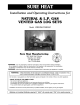
OWNER’S
MANUAL
ROBERT H. PETERSON CO. • 14724 East Proctor Avenue • City of Industry, CA 91746
Important
Read these instructions carefully and completely
before starting installation of the burner system.
This is an UNVENTED gas-fired heater. It
uses air (oxygen) from the room in which it is
installed. Provisions for adequate combustion
and ventilation air MUST be provided. See
section entitled VENTILATION AND CONFINED
SPACE INFORMATION.
This appliance is designed as an attended
appliance. Adults must be present when the unit
is operating. Do not leave this unit burning when
unattended or while anyone is sleeping.
Installation, service, and the provisions for combustion
and ventilation air MUST conform with local codes
and with the National Fuel Gas Code, ANSI Z223.1/
NFPA 54, or the CSA B149.1, Natural Gas And
Propane Installation Code.
INSTALLER: Leave this manual with the appliance
CONSUMER: Retain this manual for future reference
WARNING: If the information in this
manual is not followed exactly, a fi re or
explosion may result, causing property
damage, personal injury, or loss of life.
Do not store or use gasoline or other
fl ammable vapors and liquids in the vicinity
of this or any other appliance.
WHAT TO DO IF YOU SMELL GAS:
• Open a window.
• Do not try to light any appliance.
• Do not touch any electrical switch; do
not use any phone in your building.
• Immediately call your gas supplier from
a neighbor’s phone. Follow the gas
supplier’s instructions.
• If you cannot reach your gas supplier,
call the fi re department.
DESIGN CERTIFIED
to standards:
Unvented Room Heater
ANSI Z21.11.2-2013
and
Vented Decorative Appliance
ANSI Z21.60-2012
10-104
G21-GL-2 UNVENTED BURNER SYSTEMS
Installation and service must be performed
by a qualifi ed professional installer, service
agency, or the gas supplier.
It is imperative that you maintain
your unvented gas appliance by
having it cleaned and serviced
regularly. See pages 11, 20-23 for
details.
This appliance may be installed in an
aftermarket, permanently located,
manufactured (mobile) home where not
prohibited by local codes.
This appliance is only for use with the type of
gas indicated on the rating plate. This appliance
is not convertible for use with other gasses.
FOR INDOOR OR
OUTDOOR USE
L-F2-117
REV 2- 1610211500
Burner Systems:
G21-GL-2-18(G)-12(M)(P)
G21-GL-2-24(G)-12(M)(P)
18" 10.0 lbs
24" 12.5 lbs
FOR USE WITH
FYRE GLASS / FYRE GEMS

2
CONTENTS
L-F2-117
REV 2- 1610211500
3 SPECIFICATIONS AND REQUIREMENTS
4 IMPORTANT SAFETY INFORMATION
5 VENTILATION AND CONFINED SPACE SAFETY INFORMATION
6 MINIMUM CLEARANCES TO COMBUSTIBLES
8 PRE-INSTALLATION AND FIREPLACE PREPARATION SAFETY
9 INSTALLATION SAFETY INFORMATION
10 OPERATIONAL SAFETY INFORMATION
11 CLEANING AND SERVICING IMPORTANT INFORMATION
12 BURNER PARTS LIST
13 WHEN USED AS A VENTED DECORATIVE APPLIANCE (PER ANSI Z21.60)
13 DAMPER CLAMP INSTRUCTIONS (WHEN USE AS A VENTED DECORATIVE APPLIANCE)
13 INSTALLATION
14 INSTALL BURNER
14 INSTALL REMOTE (if equipped)
15 CONTROL SETTINGS
15 LIGHTING TEST
15 GAS PRESSURE
15 SECURE BURNER TO FLOOR
15 INSTALL GLASS PANELS
15 INSTALL REFLECTIVE COVERS
16 GLASS/GEMS PLACEMENT (purchased separately)
16 DECORATIVE MEDIA ON FIREPLACE FLOOR (optional)
17 INSTALL/REPLACE BATTERIES (IF APPLICABLE)
17 REMOTE TRANSMITTER BATTERY
17 REMOTE RECEIVER BATTERIES
18 CHECK GAS PRESSURE
18 GAS PRESSURE SPECIFICATIONS
19 LIGHTING INSTRUCTIONS - SERIES 12 VALVE
20 CLEANING AND SERVICING SAFETY INFORMATION
21 CLEANING AND SERVICING
21 TO CLEAN THE BURNER SYSTEM
21 CLEANING AND SERVICING THE ODS PILOT
22 SYNCING THE REMOTE SYSTEM (if equipped)
22 OPERATING THE BURNER SYSTEM
23 CHECKING THE ODS PILOT FLAME APPEARANCE
24 NOTES PAGE
25 TROUBLESHOOTING
28 WARRANTY

3
SPECIFICATIONS AND REQUIREMENTS
WARNING: This appliance is for installation only in a:
1. Solid-fuel-burning masonry or UL-127
factory-built fi replace, or
2. Listed ventless fi rebox enclosure.
It has been designed certifi ed for these installations.
Exception: DO NOT install this appliance in a factory
built fi replace that includes instructions stating it has not
been tested or should not be used with unvented burner
systems.
Note: Installation in any other fi replace is prohibited and
will void any approvals and warranties.
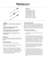
Fireplace Dimensions
Fig. 3-1
This burner system is equipped with an Oxygen
Depletion Sensor (ODS) safety pilot system. The ODS
senses the amount of oxygen available in the room and
shuts the burner system off before the oxygen level
drops below 18%. The pilot can only be relit when fresh
air is available. This may require opening a window
or a door to another room or cracking the damper
open slightly.
This burner system has been certifi ed to two standards:
UNVENTED ROOM HEATER-ANSI Z21.11.2
VENTED DECORATIVE APPLIANCE-ANSI Z21.60
Check local or state codes to determine if vent-free
heaters are permitted in your locality before you
install this burner system as a vent-free appliance. If
not permitted, you may install and operate this burner
system as a vented appliance.
This unit may not be installed in a vented fi replace with
a chimney of less than 15 feet in height.
Observing minimum fi replace dimensions and centering
the appliance in the fi replace will ensure adequate
clearance for operation and servicing. It may be
necessary to disconnect the unit for some types of
service.
Any installation of this appliance is subject to minimum fi replace size requirements below:
Specifi cation Value Qty.
Remote receiver battery type AA battery 4
Remote transmitter battery type 12V battery 1
Table 3-2 - Technical Data (if applicable)
L-F2-117
REV 2- 1610211500
Height
Width
Depth
Minimum Permanent Chimney Vent Opening
in sq. in. (when used as a vented appliance)
Table 3-1 Factory built fi replaces*
Chimney
Height
18" 24"
15'
17 18
20'
15 15
25'
13 13
30'
11 12
*For masonry-built fi replaces, add 10 sq. in. to amount shown.
Burner
Model
Minimum Fireplace Size
(refer to
Fig. 3-1)
BTU Rating
Width Depth Height Nat. Gas L.P. Gas
G21-GL-2-18
22" 16" 15" 37k 35k
G21-GL-2-24
28" 16" 15" 40k 40k

4
UNVENTED ROOM HEATER GENERAL SAFETY INFORMATION
A. WARNING: CARBON MONOXIDE POISONING MAY LEAD TO DEATH.
Early signs of carbon monoxide poisoning are similar to the fl u, with headaches, dizziness, and/or
nausea. If you have these signs, the gas appliance may not be installed correctly, or may not be
working properly. GET FRESH AIR AT ONCE! STOP USING THE APPLIANCE IMMEDIATELY!
Some people, including pregnant women; persons with heart or lung disease, asthma, or anemia;
those under the infl uence of alcohol; and persons at high altitudes, are more affected by carbon
monoxide than others. (The appliance must be serviced by a qualifi ed professional service
technician before use).
B. If any soot appears on the appliance or other areas of the fi replace in which this appliance is
installed, shut system off and call a qualifi ed professional service technician, vent-free gas
burner system technician, or your local gas company.
C. This appliance may be installed in an aftermarket, permanently located, manufactured (mobile)
home where not prohibited by local codes. Installation of appliances designed for manufactured
homes or mobile homes must conform with the Manufactured Home Construction and Safety
Standard, Title 24 CFR, Part 3280 in the U.S.; or with CAN/CSA Z240 MH, Mobile Housing in
Canada; or with ANSI/NCSBCS A225.1/NFPA 501A, Manufactured Home Installations Standard
when none of the previously referenced standard are applicable.
D. Eliminate drafts before using the gas appliance by closing heating and air conditioning vents,
returns, and outside air vents. Fans blowing directly into the fi replace must be turned off when
this appliance is operating.
E. WARNING: This appliance is for installation only in a solid-fuel-burning masonry or UL 127
factory-built fi replace or in a listed ventless fi rebox enclosure. It has been design certifi ed for these
installations. Exception: DO NOT install this appliance in a factory-built fi replace that includes
instructions stating it has not been tested or should not be used with unvented gas burner systems.
F. WARNING: DO NOT MODIFY THIS VENT-FREE HEATER OR ITS CONTROLS. Any change
may be dangerous. Improper installation or use of your vent-free gas appliance can cause
serious injury or death from fi re, burns, explosions, or carbon monoxide poisoning.
G. State and local codes may only allow operation of this appliance in a vented confi guration. Check
your state or local codes.
H. WHEN INSTALLING AS A DECORATIVE VENTED APPLIANCE, THE UNIT MUST CONFORM
TO ALL LOCAL CODES AND TO THE LATEST EDITION OF THE NATIONAL FUEL GAS CODE ANSI
Z223.1/NFPA54.
I. PETERSON (REAL FYRE) GLASS OR GEMS ARE THE ONLY MEDIA CERTIFIED TO BE
USED IN THIS BURNER. DO NOT USE ANY OTHER MEDIA.
IMPORTANT SAFETY INFORMATION
Important: For safe operation and proper performance of this product and to comply with certifi cation, listings,
and building code acceptances, use ONLY Peterson Real Fyre controls, parts, and accessories
that have been specifi cally listed or certifi ed for use with this burner system. Use of other controls,
parts, or accessories is prohibited and will void all warranties, certifi cations, listings, and building
code approvals, and may cause property damage, personal injury, and loss of life.

5
Your vent-free gas burner system SHALL NOT BE INSTALLED IN A CONFINED SPACE or unusually tight
construction unless provisions are made for adequate combustion and ventilation air.
• The National Fuel Gas Code, ANSI Z223.1/NFPA 54 defi nes a confi ned space as a space whose volume is less
than 50 cu. ft. per 1,000 BTU per hour (4.8 meters
3
per kw) of the aggregate input rating of all appliances installed
in that space.
• An unconfi ned space is a space where volume is at least 50 cu. ft. per 1,000 BTU per hour (4.8 meters
3
per kw)
of the aggregate input rating of all appliances installed in that space.
• Rooms communicating directly with the space in which the appliances are installed, through openings not furnished
with doors, are considered a part of the unconfi ned space.
(Length x Width x Height x 20 = Maximum BTUs allowed)
Example: To install a Peterson Real Fyre vent-free gas
burner system with 36,000 BTU, maximum, in a space
with no other gas-burning appliances, the space MUST be
1,800 cu. ft. or larger.
Assuming an 8' ceiling, fl oor dimensions must be a minimum
of 225 sq. ft.,
i.e.; 18'x12.5'=225 sq ft (see Fig. 5-1).
VENTILATION AND CONFINED SPACE SAFETY INFORMATION
H
W
L
L x W x H x 20 = Maximum BTU allowed
WARNING
If the area in which the heater may be operated is
smaller than that defi ned as an unconfi ned space or if
the building is of unusually tight construction, provide
adequate combustion and ventilation air by one of the
methods described in the National Fuel Gas Code, ANSI
Z223.1/NFPA 54, Air for Combustion and Ventilation, or
applicable local codes.
REMEMBER
L x W x H x 20 = MAXIMUM BTUs ALLOWED
If the space is smaller than the above formula allows,
and/or smaller than the examples and diagrams on
this page specify, DO NOT install the vent-free burner
system unless provisions for additional combustion
and ventilation air are made.
WARNING: Do not install the unvented burner system
where the room is considered a confined
space (see Fig. 5-1).
To determine if the area where this burner system is to be
installed fi ts the defi nition of an unconfi ned space, multiply
the length of the room by the width of the room by the height
of the room, then multiply by 20. The result is the maximum
BTU allowed.
Fig. 5-1
IT MAY BE NECESSARY TO OPEN A WINDOW
SLIGHTLY (1"- 2") OR OTHERWISE INCREASE
VENTILATION. CONDITIONS REQUIRING THIS
INCLUDE, BUT ARE NOT LIMITED TO:
1. Installation in a CONFINED SPACE.
2. Installation in a HOME OF UNUSUALLY
TIGHT CONSTRUCTION**.
3. Installation at HIGH ALTITUDES.
4. Certain MEDICAL OR PHYSICAL
CONDITIONS OF THE HOMEOWNER that
may be adversely impacted by combustion
products created by burning natural or
propane gas.
Installation in a tightly constructed home and/
or installation at high altitudes may cause your
vent-free burner system to produce excessive heat or
excessive moisture. The oxygen depletion sensor may
shut down the burner system. These conditions may be
corrected by opening a window or otherwise increasing
the number of air changes in the home.
**
Unusually tight construction is defi ned as construction where:
a. Walls and ceilings exposed to the outside atmosphere have a
continuous water vapor retarder with a rating of 1 perm (6x10
-
11
kg
per pa-sec-m
2
), or less with openings gasketed or sealed;
b. Weather stripping has been added on openable windows and
doors, and
c. Caulking or sealants are applied to areas such as joints around
window and door frames, between sole plates and fl oors, between
wall-ceiling joints, between wall panels, at penetrations for plumbing,
electrical, and gas lines, and at other openings.
The Peterson Real Fyre vent-free burner system
has been certifi ed to function safely and reliably with
emission by-products well within accepted safety and
health standards. Your specifi c medical or physical
condition may render you more sensitive to products
created by burning natural or propane gas. If this is the
case, you should open a window or otherwise increase
ventilation.

6
MINIMUM CLEARANCES TO COMBUSTIBLES
If the vent-free burner system is installed in a factory
built fi replace, follow the manufacturer’s guidelines for
minimum clearances to combustibles.
In the absence of such guidelines, follow the instructions
below:
Clearances to Combustible Construction:
Sidewalls
: 6" from side of fi replace opening (Fig. 6-1).
Ceiling: 42" from top of fi replace opening (Fig. 6-1).
Flooring: See IN FRONT OF FIREPLACE section below.
Mantel: See ABOVE THE FIREPLACE section below &
Fig. 6-1. Also see Fig. x-1, & x-2 on following page).
Note: Clearances to combustible construction
are those distances required to ensure that
fi replace mantels, facings, walls, ceilings, and
fl oorings will not catch fi re.
In most cases, these clearances should also be
adequate to prevent any discoloration or warping due
to heat. However, every gas burner installation presents
a different and unique set of circumstances involving
many variables beyond the control of the manufacturer.
These include paint or fi nish composition, previous
exposure to heat, methods and quality of construction,
air fl ow patterns, glass doors, fans or blowers, etc.
Because of these variables, we cannot guarantee that
heat warping or discoloration will never occur. The
potential for heat warping or discoloration may exist
no matter what item(s) you are burning in the fi replace,
including wood.
The dimensions in Fig.
6-1 are MINIMUM
CLEARANCES to maintain when you install this
burner system. BOTH SIDES of the fi replace opening
MUST BE AT LEAST 6" from any combustible
sidewalls. The ceiling MUST BE at least 42" from
the top of the fi replace opening.
ABOVE THE FIREPLACE:
To install the vent-free burner system, there must ALWAYS be noncombustible or heat resistant material
immediately above the fi replace opening. Heat resistant materials (i.e., marble or slate) must be at least
5
/
8
"
thick. Sheet metal should not be installed onto combustible materials.
If you DO NOT install a fi replace hood, there MUST be at least 12" of noncombustible or heat resistant material
immediately above the fi replace opening (see A in Fig. x-1 on the following page). If you DO install a fi replace
hood, there MUST be at least 10" of noncombustible or heat resistant material immediately above the fi replace
opening (see B in Fig. x-2 on the following page). If there is a wooden mantel, shelf, or other combustible
projection above the fi replace, follow the information in the Figures on the next page.
EXAMPLE: If the fi replace has a combustible projection (mantel or shelf) 20" above the top of the fi rebox,
the maximum horizontal projection out from the face of the fi replace will be:
1. If a fi replace hood is not installed - 2.5" (see Fig. x-1 on the following page).
2. If a fi replace hood is installed ------ 10" (see Fig. x-2 on the following page).
A fi replace hood defl ects heat away from the fi replace face and mantel, reducing the potential for heat related
warping or discoloration. The use of a fi replace hood is highly recommended.
DO NOT place any combustible decorations/items on the mantel or above the fi replace.
IF YOU CANNOT MEET THESE MINIMUM CLEARANCES, YOU MUST OPERATE THE VENT-FREE
BURNER SYSTEM WITH THE CHIMNEY FLUE DAMPER OPEN.
IN FRONT OF THE FIREPLACE:
Be certain that combustible fl ooring material (i.e.: carpet, tile, etc.) is not too close to the vent-free unit. If the
vent-free burner system is at fl oor level or less than 6" above the fl oor, there MUST be at least 12" (1 foot) of
noncombustible material between the front of the fi replace and any combustible fl ooring.
Front
Front
Front
Back
min. 42"
min
min. 42"
6"
min
6"
Rear
opening
Front
opening
Depth Depth
Front
opening width
Back
opening width
Height
Height
Fig. 6-1
Minimum clearances to
side walls and ceiling
Side wall: 16" from side of fi replace opening.
Ceiling: 42" from top of fi replace opening.

7
MINIMUM CLEARANCES TO COMBUSTIBLES (Cont.)
IF YOU CANNOT MEET THESE MINIMUM CLEARANCES, YOU MUST OPERATE THE VENT-FREE GAS
BURNER SYSTEM WITH THE CHIMNEY FLUE DAMPER OPEN.
8"
24"
22"
15"
Firebox
Firebox
14"
12"
10"
8"
6"
2.5"
.75"
Any combustible material
(mantel) must be within the
shaded area as shown above
10"
12"
1.5"
6"
2.5"
17"
20"
14"
12"
10"
Top of firebox
Fire resistant material
Horizontal projection
from face of fireplace
* Standard Fireplace Hood with minimum 4" horizontal projection
Mantel clearance with hood *
Mantel clearance without hood
Fireplace hood with minimum
4" horizontal projection
12"
20"
25"
28"
32"
30"
34"
BA
Fig. 7-1 Fig. 7-2
12"
8"
4"
2"
4"
6"
Side mantel
Fireplace
opening top
view
Fig. 7-3
Side mantel clearance

8
WARNING
THIS APPLIANCE IS EQUIPPED FOR EITHER NATURAL OR PROPANE GAS.
FIELD CONVERSION IS NOT PERMITTED.
PRE-INSTALLATION AND FIREPLACE PREPARATION SAFETY
PRE-INSTALLATION AND FIREPLACE PREPARATION SAFETY GUIDELINES
A. CAUTION: If not installed, serviced, and used correctly per these instructions, this product can cause
serious personal injury, property damage, or loss of life.
B. WARNING: Before installing in a solid-fuel-burning fi replace, the chimney fl ue, damper, and fi rebox must
be thoroughly CLEANED of soot, creosote, ashes, and loose paint by a qualifi ed chimney cleaner. Some
fi replaces (especially older ones) may need repair prior to installing this appliance.
C. This appliance is only for use with the type of gas indicated on the rating plate. This appliance is NOT
CONVERTIBLE for use with other gasses.
CHECK GAS TYPE (natural or L.P): The gas supply must be the same as stated on your burner system
rating plate. If gas supply is different, DO NOT INSTALL. Contact your dealer for immediate assistance.
D. Any outside air ducts and/or ash dumps located on the fl oor or walls of the fi replace must be permanently
sealed shut before the installation. Use a heat-resistant sealant. Do not seal the chimney fl ue damper.
E. INSUFFICIENT GAS PRESSURE WILL KEEP THE ODS (OXYGEN DEPLETION SENSOR) PILOT
FROM OPERATING PROPERLY. DO NOT USE IF GAS PRESSURE IS LOWER THAN THE MINIMUM
REQUIREMENT.
F. The minimum inlet gas-supply pressure for purposes of input adjustment is 5" water column (w.c.) on natural
gas and 11" w.c. on L.P. gas. Insuffi cient gas pressure will affect proper operation of the ODS pilot. Do not
install this gas appliance if minimum pressure is not available. The maximum inlet gas-supply pressure is
10.5" w.c. on natural gas and 13" w.c. on L.P. gas. The L.P. source must be regulated. (Do not connect this
appliance directly to an unregulated L.P. gas tank - this can cause an explosion.) Do not connect
this appliance to a portable L.P. gas cylinder.
G. The gas piping system must be sized to provide minimum inlet pressure at the maximum fl ow rate
(BTU/hr). Undue pressure loss will occur if the pipe is too small, or the run is too long. Gas supply pipe must
be
1
/
2
" minimum interior diameter. If the gas line is longer than 20', a larger diameter line may be necessary.
Refer to the NFPA 54 guidelines for further details.
H. The minimum clearance from the fi replace opening to combustible materials on side walls and ceiling must
be maintained as outlined in MINIMUM CLEARANCE TO COMBUSTIBLES - WALLS AND CEILING.
I. At least 10"-12" of noncombustible or heat-resistant material is required above the fi replace. A fi replace
hood will be required to act as a heat defl ector in protecting combustible fi replace surrounds (facing and/or
mantel) if certain minimum clearances cannot be met.
J. Be certain that combustible fl ooring material (i.e., carpet, tile, etc.) is not too close to this gas appliance. If
this appliance is at fl oor level or less than 6" above the fl oor, there must be at least 12" of noncombustible
material between the base of the fi replace and any combustible fl ooring.
K. Input ratings shown in BTU per hour are for elevations up to 2,000 ft. For elevations above 2,000 ft., refer
to the National Fuel Gas Code or contact the Robert H. Peterson Company before installing this product.
L. This gas appliance and its main gas valve must be disconnected from the gas-supply piping system during
any pressure testing of that system at test pressures in excess of
1
/
2
psig.
M. This gas appliance must be isolated from the gas-supply piping system by closing the equipment shutoff
valve connected to the gas-supply line during any pressure testing of the gas-supply piping system at test
pressures equal to or less than
1
/
2
psig.
N. Do not use this appliance if any part has been underwater. Immediately call a qualifi ed professional service
technician to inspect the appliance and to replace any part of the control system and any gas control that
has been underwater.
CAUTION: Installation and repair must be done by an NFI certifi ed or other qualifi ed professional installer.
Installer: Carefully read these instructions before installing this gas burner system. Be sure you understand
all safety precautions and warnings contained in this manual.

9
INSTALLATION SAFETY INFORMATION
INSTALLATION SAFETY GUIDELINES
A. Carefully inspect the burner and cartons for shipping damage. If any parts are missing/damaged, call your
dealer. Do not attempt to install the appliance unless all parts are in good condition.
B. Correct installation of the glass/gems and proper placement and installation of the burner assembly, are
imperative to safe operation of your appliance. Problems WILL occur if all items are not properly installed.
Reference the INSTALLATION section.
C. When installing in a wood-burning fi replace, center the appliance in the fi replace while making certain
that no part of the assembly protrudes (forward) beyond the face of the fi replace.
DO NOT PUSH THE UNIT ALL THE WAY TO THE BACK.
D. The correct amount of glass/gems must be used on your burner system for it to operate properly. You
may use additional glass/gems, or lava granules to cover the fl oor of the fi replace. Please read the entire
DECORATIVE MEDIA PLACEMENT section for details.
E. DO NOT PLACE other accessories, such as wood chips, pine cones, or Lava Granules on this appliance.
These items will cause improper burning, sooting, and/or high levels of carbon monoxide. Additional
accessories may be placed around the burner system, as long as they do not interfere with the burning
of your gas appliance.
F. Due to high temperatures, this appliance should be located out of traffi c and away from furniture/
draperies.
G. A fi replace screen must be in place when this gas appliance is in operation. Unless other provisions for
combustion air are provided, the screen shall have an opening(s) for introduction of combustion air.
H. Connecting directly to an unregulated L.P. tank can cause an explosion.
I. Special care is required if you are installing the unit into a SUNKEN FIREPLACE. You must raise the
fi replace fl oor to allow access to gas controls. This will ensure adequate airfl ow and guard against sooting.
Raise the fi replace fl oor using noncombustible materials.
J. A vent-free room heater having an input rating of more than 10,000 BTU per hour shall not be installed
in a bedroom (ANSI Z21.11.2).
If local codes allow, you may install a G8E-xxR burner, having a rating of 9,500 BTU, in a bedroom. An
unvented room heater having an input rating of more than 6,000 BTU per hour shall not be installed in
a bathroom (ANSI Z21.11.2).
Fireplace Floor Requirement
DO NOT install this burner system if the fi replace hearth is recessed. The fi replace fl oor must be at
the same level as or larger than the fi replace front opening. An ash lip or recess may not exceed
3
/
4
". See
Fig. 9-1 below.
Note: If glass doors are used: the fi replace fl oor must not be blocked by the door frame; the frame must
have openings to allow for fresh air circulation.
Fig. 9-1
Fireplace
fl oor
Fireplace
opening
(burner
system)
ASH LIP OR
RECESS
ABOVE
3
/4"
NOT
PERMITTED
Max.
3
/4
"
ASH LIP OR
RECESS UP
TO
3
/4"
PERMITTED

10
OPERATIONAL SAFETY INFORMATION
OPERATING YOUR UNVENTED GAS APPLIANCE SAFELY AND CORRECTLY
A. SOLID FUEL MUST NOT BE BURNED in a fi replace where this vent-free gas appliance
is installed.
B. GLASS DOORS MUST BE FULLY OPEN when this vent-free gas appliance is operating.
This appliance MUST NOT BE ON if glass doors are closed, as it can lead to sooting,
burner outages, and possibly explosion, causing damage or injury.
C. WARNING: DO NOT ALLOW DRAFTS INTO OR AROUND THE FIREPLACE. CLOSE
(SHUT) HEATING AND AIR CONDITIONING VENTS, RETURNS, AND OUTSIDE AIR
VENTS. DO NOT OPERATE FANS (WINDOW FANS, CEILING FANS, FLOOR FANS),
WHICH MAY ALTER FLAME PATTERNS. Sooting, excess carbon monoxide, or ODS
pilot outages may occur due to drafts.
D. WARNING: DO NOT USE A BLOWER INSERT, HEAT EXCHANGER INSERT, or any
other accessory that is not specifi cally certifi ed for use with this vent-free gas appliance.
E. Make sure there is adequate combustion and ventilation air when this gas appliance is
operating. You may need to crack the damper or open a window slightly.
F. THIS APPLIANCE MUST BE MAINTAINED IN A WELL-CLEANED CONDITION AT ALL
TIMES. REGULAR (AT LEAST ONCE PER YEAR) CLEANING OF THE BURNER AND
ODS PILOT IS REQUIRED BY A QUALIFIED PROFESSIONAL SERVICE TECHNICIAN.
G. To light this appliance, it may be necessary to purge the unit for longer than one minute
after long periods of non-use.
H. If you operate this vent-free gas appliance fueled by L.P., operating characteristics may
vary as the fuel in the tank approaches empty (less than
1
/
4
full). Sooting and other
increases in combustion by-products will occur. Turn off the appliance, refi ll the L.P. tank,
and have the burners cleaned.
I. During manufacturing, various parts of this unit are treated with oils or paints. Though not
harmful, they may produce annoying smoke and smells as they are burned off during initial
operation. This is a normal occurrence. Initial break-in period should last four to six hours;
maximum ventilation should be provided by opening windows, doors, or chimney fl ue.
J. Keep the area around your gas appliance clear of combustible materials, gasoline, and any
other fl ammable vapors/liquids. Provide adequate clearance for servicing and operation.
Be especially cautious if this gas appliance is installed in a basement or converted garage.
K. Do not place clothing or any fl ammable material on or near your vent-free gas appliance.
Matches, paper, garbage, or any other material must not be thrown on top of the glass/
gems, burner, or into the fl ame.
L. Young children should be carefully supervised when in the same room with this
appliance.
M. Children and adults should be alerted to the hazard of high surface temperatures and should
stay away to avoid burns or clothing ignition.

11
OPERATIONAL SAFETY INFORMATION (Cont.)
OPERATING YOUR UNVENTED GAS APPLIANCE SAFELY AND CORRECTLY
N. This appliance is intended for supplemental heating, and is not a primary heating
source. Water vapor produced by vent-free burner systems can create moisture problems
in a home when operated for extended periods of time. If condensation begins to occur,
open your damper or a window.
O. If the gas quality is poor or pressure low, your ODS pilot may not stay lit, the burners
may produce soot, or the unit may backfi re. Contact your local gas supplier immediately.
P. This appliance is designed for adults to be present while in operation. Do not leave this
unit burning when unattended or while sleeping. This is an attended appliance.
Q. WARNING: Failure to keep the primary air opening(s) of the burner(s) clean may result
in sooting and property damage.
R. WARNING: All previously applied loose material must be removed prior to
reapplication. All replacement loose material must be purchased from the original
appliance manufacturer.
S. Unusually tight construction is defi ned as:
a. Walls and ceilings exposed to the outside atmosphere have a continuous water vapor
retarder with a rating of 1 perm (6x10
11
kg per pa-sec-m
2
) or less with openings that
are sealed or use gaskets;
b. Weather stripping has been added on openable windows and doors; AND
c. Caulking or sealants are applied to areas such as joints around window and door
frames; between sole plates and fl oors; between wall-ceiling joints; between wall
panels; at penetrations for plumbing, electrical, and gas lines; and at other openings.
T. Burning candles, air fresheners and sprays will cause objectionable odors to be created
by the unvented burner system.
CLEANING AND SERVICING IMPORTANT INFORMATION
It is imperative that you maintain your unvented gas appliance
by having it cleaned and serviced regularly. A qualifi ed
professional service technician shall inspect and service this
unit at least annually. (Read and follow the CLEANING AND
SERVICING sections for details.)
Failure to provide reasonable and necessary maintenance as
outlined in the owner’s manual will cause your appliance to
malfunction and will void your warranty.

12
BURNER PARTS LIST
Note: Photos not to scale
Replacement parts can be ordered
from your local Real Fyre dealer.
24" Model shown
No
te
:
Ph
ot
os
Control valve (w/ refl ector removed)
ODS pilot assembly
Bottom view
1
2
3
4
5
6
7
8
12
13
9
10
Glass/gems are available in 5, 7.5, or 10 lb bags, in various colors; contact your dealer for further details.
Glass/gems are purchased & packaged separately. Amount varies depending on model size;
18" model 24" model
Item Description Part No. Qty. Part No. Qty.
1. Burner assembly (w/ venturi tube) GG21-2-18 1 GG21-2-24 1
2.
or
ODS pilot assembly (natural)
ODS pilot assembly (propane)
ODS-0003
ODS-0004
1
1
ODS-0003
ODS-0004
1
1
3.
or
Control valve (natural)
Control valve (propane)
SV-43
SV-43P
1
1
SV-43
SV-43P
1
1
4. Glass panels G21-06-18 2 G21-06-24 2
5.
or
Refl ective covers (removable, shown installed)
Rose gold refl ective covers
G21-03-18
G21-03G-18
2
2
G21-03-24
G21-03G-24
2
2
6. Piezo igniter PZ-1 1 PZ-1 1
7. On/Off switch SW-9 1 SW-9 1
8. Flex connector (w/ adapter), 3/8" O.D. X 30" CK-10 1 CK-10 1
9.
Remote kit
*
(includes receiver, transmitter, batteries, plastic cover)
RR-1A 1 RR-1A 1
10.
Remote transmitter (only) *
AT-R1-1 1 AT-R1-1 1
11.
Metal heat shield (only)
*
HS-47 1 HS-47 1
12. Damper clamp DC-1 1 DC-1 1
13. Hammer screws (pair) G21-05 1 G21-05 1
* If equipped
18" 10.0 lbs [(1) 10 lb bag]
24" 12.5 lbs [(1) 5 lb bag & (1) 7.5 lb bag]
11

13
WHEN USED AS A VENTED DECORATIVE APPLIANCE (PER ANSI Z21.60)
This burner system may be installed as vented decorative appliance in compliance with ANSI Z21.60 and National
Fuel Gas Code, Section 6.6. The minimum permanent free opening of the fi replace chimney or chimney damper
must be met per the Chimney Vent Opening Table on pg 3 of this manual. Chimney damper must be fi xed in a
manner to maintain permanent free opening at all times. To accomplish this, install a screw or bolt in the edge of
the damper to prevent closing, or drill holes in the damper or remove the damper.
INSTALLATION
BEFORE PROCEEDING, CAREFULLY READ ALL OF THE IMPORTANT SAFETY INFORMATION CONTAINED
IN THIS OWNER’S MANUAL, INCLUDING:
A. Pre-Installation and Fireplace Preparation Safety Guidelines
B. Ventilation and Confi ned Space Information
C. Installation Safety Guidelines
1. Adjustable open-ended wrench
2. Pliers
3. Propane gas-resistant pipe compound or Tefl on
tape
4. Soapy water solution and brush for leak detection
5. Standard screwdriver
6. Manometer (for checking gas pressure)
Tools Required:
Note: To install the unvented gas burner system, the fi replace must have a gas-supply line that has been
installed by a qualifi ed professional service technician in accordance with all local codes. Refer
to the PARTS LIST when installing the burner system.
IMPORTANT
Be sure you have read and understand all safety precautions and warnings
contained in this manual.
WARNING: Failure to position these parts in accordance with these diagrams or failure
to use only parts specifi cally approved with this unvented burner system
may result in property damage or personal injury.
This appliance is for installation in a solid-fuel-burning fi replace (masonry fi replace or manufactured fi replace)
with a working fl ue and constructed of noncombustible material.
CHECK GAS TYPE (natural or propane). The gas supply must be the same as stated on the burner system
rating plate. If the gas supply is different, DO NOT INSTALL. Contact the dealer for immediate assistance.
WARNING
Do not connect this appliance directly to a high-pressure natural gas line or an unregulated propane tank.
DAMPER CLAMP INSTRUCTIONS (WHEN USE AS A VENTED DECORATIVE APPLIANCE)
If the burner system is installed as a vented decorative appliance:
The damper clamp with hex bolt (Fig. 13-1) is provided as a means to prevent
full closure of the damper blade. The clamp is easily attached to most damper
blades with pliers or a wrench, and must be permanently installed. The clamp
is designed to prevent accidental closure of the damper when installed as
illustrated (Fig. 13-2 and Fig. 13-3). Should the
clamp not fi t, or fail to provide the permanent vent
opening specifi ed in Table 3-1, have a permanent
stop installed, remove the damper blade, or have
the damper cut to provide the minimum permanent
opening required.
Damper clamp
Fig. 13-1
Set screw
Fig. 13-2 Fig. 13-3
Open
Closed
The damper clamp is not required if the burner
system is installed as an unvented room heater.

14
INSTALLATION (cont.)
REFER TO THE BURNER PARTS LIST WHEN FOLLOWING
THESE INSTRUCTIONS.
24" burner model shown here.
INSTALL BURNER
1. MAKE SURE THE FIREPLACE GAS SUPPLY IS
TURNED OFF.
2. Locate the gas-supply stub inside the fi replace and
remove the cap, if attached (reference Fig. 14-1).
CAUTION: When removing the cap, make sure the stub does
not turn, loosening the connection inside the wall.
3. Place the burner system in the fi replace. Center the
burner in the fi replace. See Fig. 14-2.
4. Be sure gas to the fi replace is off. Remove the adapter
connected to the fl ex connector (pre-installed on the
burner system). Attach the adapter to the gas-supply stub
using a pipe compound resistant to all gasses. Tighten
securely. Then attach the open end of the fl ex connector
to the adapter. Tighten securely. (See Fig. 14-1.)
5. LEAK TEST: Turn on the fi replace gas supply, and test
at all connections for leaks using the appropriate soapy
water solution. If bubbles appear, a leak is present. Turn
off the gas and tighten at all connections. Repeat until
no leaks are present. If a leak persists, turn off the gas
supply and contact the local gas company or dealer.
NEVER USE A FLAME TO CHECK FOR LEAKS.
INSTALL REMOTE (if equipped)
1. At this stage the remote system batteries are to be
installed. Reference the INSTALL/REPLACE BATTERIES
section for details.
2. Locate the wires coming off of the remote receiver, and
connect them to the two male prongs found on the valve
(see Fig. 14-3).
3. Route the wires into the burner and out of the left
side, then place the remote receiver with metal heat
shield at the front left corner of the fi replace. Place
as far from the burner system as possible. See Fig. 14-4.
Fig. 14-3 Connect remote receiver to valve
Connect wires
to male prongs
on valve
The Real Fyre burner system must be installed by a qualifi ed professional service technician. Instructions
must be followed carefully to ensure proper performance and full benefi t from the burner system. Fireplace
fl oor must be level, clean, and smooth.
Important: When the burner system is installed outdoors, ensure it is not directly exposed to the
elements (precipitation, rain, wind, etc.).
Fig. 14-1 Connect gas supply
Fig. 14-2 Center burner in fi replace
Flex connector
Adapter
Gas supply stub
Burner
Fig. 14-4 Place remote receiver
Receiver (w/ heat shield)

15
INSTALLATION (Cont.)
CONTROL SETTINGS
It is recommended that before you install the decorative media,
you familiarize yourself with the control valve layout. This will
assist you when operating the burner system. See Fig. 15-1
for the control positions.
LIGHTING TEST
Prior to proceeding with installation, perform a lighting test
(see lighting instructions for lighting your burner). Allow unit
to completely cool after testing.
GAS PRESSURE
At this stage, the gas pressure is to be checked. Reference
the CHECK GAS PRESSURE section for details.
SECURE BURNER TO FLOOR
1. The burner system must be secured to the fi replace fl oor.
The unit has anchoring tabs located on the bottom ends.
With the unit centered, mark and then drill two
1
/
4
" pilot
holes, one on each side of the burner, on opposite ends.
2. Reposition the burner over the pilot holes and insert the
provided hammer screws. Carefully hammer the screws
in as shown in Fig. 15-2.
3. Use a power drill to complete the fastening of the screws
(Fig. 15-3).
Note: If you have a manufactured fi replace, check with the
manufacturer before drilling holes in the fl oor.
INSTALL GLASS PANELS
Each side of the burner has tabs designed to hold the glass
panels in place. First loosen the screws on the tabs with a
screwdriver. Then position a glass panel in place, secure the
tabs up against the panel, and fasten the screws. Repeat for
the opposite side. Reference Fig. 15-4 and Fig. 15-5.
INSTALL REFLECTIVE COVERS
Remove the protective coating off of the refl ective front covers.
DO NOT use a sharp object to remove coating. Install the
covers onto each side of the burner system (see Fig. 15- 6).
Turn off the gas supply prior to proceeding.
Fig. 15-1 Control valve operating positions
OFF PILOT ON
Read settings here
Fig. 15-6 Front cover installed
Fig. 15-4 Glass Panel Positioning
Fig. 15-5 Securing Glass Panel
Fig. 15-2 Install hammer screws
Fig. 15-3 Fasten hammer screws
IMPORTANT
For all valves, the air MUST be purged from the gas line
before the pilot will light and burn properly. The time
needed to purge will depend on the length of the gas line
to the unit and the amount of time since the unit or gas
line was last used. It may take several minutes before all
the air is purged and the pilot will light and burn properly.
Reference the LIGHTING INSTRUCTIONS section in
this manual.

16
GLASS/GEMS PLACEMENT (purchased separately)
CAUTION: Glass pieces may have sharp edges. Be careful
handling the glass. Use hand protection, such as
gloves, if necessary.
Glass/gems (purchased separately) must be installed on the
burner for the system to operate properly. See the table below
for correct amounts of media for each model. Glass/gems are
available in various colors; contact your dealer for further details.
Pour the glass/gems directly on top of the burner so that the
burner pan is covered completely and evenly (see Fig. 16-1).
Important: When installing glass on your burner; DO NOT
use the fi ne glass particles that have settled
at the bottom of the glass bag. These particles
will adversely affect the fl ame pattern.
Important: Do not add any additional glass/gems to this
burner system. Any additional glass/gems may
cause unsafe operation.
WARNING: All previously applied loose material must be
removed prior to reapplication. All replacement
loose material must be purchased from the
R.H. Peterson Co.
DECORATIVE MEDIA ON FIREPLACE FLOOR
(optional)
Glass media or granules may be placed on the fi replace fl oor
as an enhancement to the burner system.
If purchased; spread the decorative media on the fl oor of the
fi replace, around all sides of the burner system. See Fig. 11-2
for an example (refl ective black glass shown). The media may
be placed around the remote receiver (as applicable). Leave
the front of the receiver clear for control access.
CAUTION: DO NOT place any of this additional media into
or onto the burner system .
INSTALLATION (cont.)
CAUTION: BURN HAZARD! Glass and/or gems on burner system will remain hot for some time
after use. You must maintain the placement as shown to ensure proper operation of the
burner system. If you need to reposition any media to maintain the proper layout, use heat-
resistant gloves or allow media adequate time to cool before handling.
Fig. 16-1 Glass/gems placement
Fig. 16-2 Decorative media fl oor placement
(Gems shown in burner)
(Glass shown on fl oor)
Model Size
Correct Amount of
Fyre Glass/Gems to Use
18" 10.0 lbs
24" 12.5 lbs

17
INSTALL/REPLACE BATTERIES (IF APPLICABLE)
CAUTION: Ensure the unit is connected to the gas line
and has been tested for leaks before you insert
batteries.
CAUTION: Turn off the remote and/or burner and allow
the unit to completely cool prior to any battery
replacements.
Important: Low/dead batteries will affect burner system
operation. Replace batteries any time the
burner will not turn on.
REMOTE TRANSMITTER BATTERY
The remote transmitter requires one 12V battery to operate
(included). Locate the transmitter, remove the lid (found on
rear), and properly insert the new battery as marked. Re-secure
the lid. See Fig. 17-1.
REMOTE RECEIVER BATTERIES
The remote receiver requires 4 AA batteries to operate
(included). Locate the remote receiver and turn it over. Slide
open the lid, and properly insert the new batteries as marked.
See Fig. 17-2.
Replace the lid, then re-position the remote receiver in the
fi replace.
Fig. 17-1 Transmitter battery
Remove
lid for
12V
battery
access
AA batteries
Fig. 17-2 Remote receiver batteries

18
NATURAL GAS PROPANE GAS
Outlet pressure reading:
(Flame adjustment on high)
3.5" w.c.
Outlet pressure reading:
(Flame adjustment on high)
10" w.c.
Inlet pressure reading
Max. 10.5" w.c.
Min. 5" w.c.
Inlet pressure reading
Max. 13" w.c.
Min. 11" w.c.
Check the valve regulator pressure at the pressure inlet point.
Turn the inlet screw counterclockwise 2 or 3 turns and then
place the tubing of the pressure gauge over the pressure
inlet point. (The test “inlet” tap is marked IN.) After taking
the pressure reading, turn the inlet screw clockwise fi rmly to
reseal. Do not over-torque. Check for gas leaks.
GAS PRESSURE SPECIFICATIONS
Fig. 18-1 12 valve: check pressure
Inlet
Outlet
CHECK GAS PRESSURE
IMPORTANT
Check the gas pressure with the
system burning and the control fully ON.
The burner system and its main gas valve must be
disconnected from the gas-supply piping system during any
pressure testing of that system at test pressures in excess of
1
/
2
psig (3.5 kPa). The burner system must be isolated from
the gas-supply piping system by closing its equipment shutoff
valve during any pressure testing of the gas-supply piping
system at test pressures equal to or less than
1
/
2
psig (3.5
kPa). This is accomplished by closing the gas-supply line valve.

19
When shutting your burner down, be sure to TURN THE
FLAME FULLY OFF (to PILOT or OFF). Make sure the
burner is completely off for one minute before relighting.
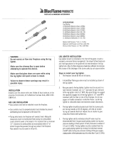
ADJUSTING THE ODS PILOT
a. The ODS pilot fl ame should encircle the generator
tip, and is preset at the factory (
Fig. 19-2).
Ordinarily, the ODS pilot will not require field
adjustment.
b. If adjustment is necessary, remove the cap screw
(
Fig. 19-1) and turn the smaller gas adjustment
screw inside
counterclockwise to increase the
ODS pilot fl ame, and
clockwise to decrease
the ODS pilot fl ame. Replace the cap screw.
MAINTENANCE
Your pan burner is equipped with a safety ODS pilot
that will shut off the gas supply in case the ODS pilot is
not burning or functioning properly. Make sure the ODS
pilot is adjusted properly and that the generator spade
clips are tightly connected to the terminal screws on
the valve. If the ODS pilot will not stay lit, call your local
gas utility or gas supplier.
A periodic check of the following should be performed
at least annually by a qualifi ed professional service
representative:
1. Valves and switch for proper operation.
2. Flue system for rust, damage, or leaks.
3. Damper operation.
4. Orifi ces for dirt or other foreign matter.
5. Visual check on the burner.
If this unit was shipped with a remote, or if a remote
system was installed later, read and follow the
separate remote instructions to operate the burner
remotely.
WARNING
If you do not follow these instructions exactly, a fi re or explosion may result, causing property
damage, personal injury, or loss of life.
Do not use this appliance if any part has been underwater. Immediately call for a qualifi ed professional service technician
to inspect the appliance and to replace any part of the control system and any gas control that has been underwater.
FOR YOUR SAFETY, READ BEFORE LIGHTING
LIGHTING THE ODS PILOT
To read the safety valve control knob (Fig. 19-1),
read the marking nearest the teardrop-shaped metal
pointer.
1. If the safety valve control knob is in the PILOT
position, push in slightly on the knob and rotate it
clockwise
to the OFF position.
2. Release knob and wait fi ve minutes.
3. Turn safety valve knob counterclockwise to the
PILOT position. (Only the ODS pilot gas will fl ow
when the knob is pushed in.)
4. Place a long match or a butane lighter at the ODS
pilot burner, and at the same time, push the safety
valve knob fully in. The ODS pilot will light.
5. Hold the safety valve knob in for approximately 60
seconds before releasing.
6. If the ODS pilot does not stay lit, turn the safety
valve knob clockwise
to the full OFF position.
Wait fi ve minutes, then repeat steps 3 through 5.
IGNITING THE MAIN BURNER
With the ODS pilot lit, turn the safety valve knob
counterclockwise to the ON position. Flip the switch
control to the ON position and the burner will light.
Refer
to the PARTS LIST for the switch location.
SHUTTING OFF THE MAIN BURNER
Flip the switch control to the OFF position. The ODS
pilot will remain lit.
SHUTTING OFF THE ODS PILOT
Be sure the switch control is OFF and depress and turn
the safety valve knob
clockwise to the OFF position.
Note: ODS pilot fl ame should encircle top of the thermopile
Fig. 19-2 Lighting the ODS pilot
LIGHTING INSTRUCTIONS - SERIES 12 VALVE
The Real Fyre burner system has an ODS (Oxygen Depletion Sensor) pilot which can be lit by hand using a match or lighter.
When lighting the ODS pilot, follow these instructions exactly.
BEFORE LIGHTING, smell all around the burner area for gas. Be sure to smell next to the fl oor as some gas is heavier than
air and will settle on the fl oor. IF YOU SMELL GAS, FOLLOW THE INSTRUCTIONS ON P. 1.
Use only your hand to push in or turn the gas control knob. Never use tools. If the knob will not push in or turn by hand, don't
try to repair it. Call a qualifi ed professional service technician. Force or attempted repair may result in fi re or explosion.
Flame touching
Thermocouple
IN
TH
TP
TH
TP
IN
OUT
Fig. 19-1
Wiring harness
ODS pilot
cap screw
HI/LO fl ame
height knob
ODS pilot
gas port
Safety
valve
control
knob
To remote
(if applicable)
Switch
The Real Fyre burner system has an ODS (Oxygen Depletion Sensor) pilot that can be lit by using the built in piezo igniter switch
on the burner, or by hand using a match or long necked lighter. When lighting the ODS pilot, follow these instructions exactly.
4. Push and hold the safety valve knob fully in and
push in the piezo igniter button several times until
the ODS pilot lights.
IN
TH
TP
TH
TP
IN
OUT
Wiring harness
ODS pilot
cap screw
ODS pilot
gas port
Safety
valve
control
knob
To remote
(if applicable)
Switch
Fig. 19-1

20
CLEANING AND SERVICING SAFETY INFORMATION
Note: Regular cleaning and servicing will be necessary to ensure proper ODS pilot operation and proper burn
characteristics.
1. Always shut off the gas to the burner system while performing service work.
2. Allow the burner system to cool before servicing.
3. Installation, service, and repair must be done by an NFI Certifi ed or other qualifi ed professional
service technician. The appliance MUST be inspected before use, and cleaned at least annually to
prevent burner shutdown, sooting, odors, etc. by a qualifi ed professional service technician. It must
be checked for clean burning operation and proper ODS pilot appearance, with the correct tools to
service this unit. More frequent cleaning may be required. Excessive lint can build up on this unit from
carpeting, bedding material, pet hairs, or other particles in the air. It is imperative that all control components
and compartments, burner(s), and circulating air passageways of the appliance be kept clean and free of
all obstructions. The ODS pilot is especially sensitive to a dirty environment and will not function properly if
dirty. Make certain all air openings are clean and free of obstructions, including:
a. The air intake openings on the ODS pilot assembly.
b. The ODS pilot opening.
c. The air shutter on the burner.
WARNING: Failure to keep the primary air openings of the burner clean may result in sooting and property
damage.
d. All of the ports on the burner. (See the CLEANING AND SERVICING section.)
4. Any safety screen or guard removed for servicing must be replaced prior to operating this burner
system.
5. Should the burner need to be removed for servicing: fi rst unfasten the screw, then use a fl at head
screwdriver to pry up the anchoring tab until the wedge anchor pops out. See Fig. 20-3. The screw assembly
is reusable.
ODS pilot
ODS pilot
opening
Air intake
openings
(on each side)
Fig. 20-2
12 model shown
Fig. 20-1
ODS pilot (on side)
Burner ports
Gas valve
(behind refl ective cover)
A
(Remove)
B
(pry up)
Fig. 20-3
/