Page is loading ...

INVERTER SCHOOL TEXT
INVERTER MAINTENANCE COURSE
Specifications subject to change without notice.
When exported from Japan, this manual does not require application to the
Ministry of Economy, Trade and Industry for service transaction permission.
HEAD OFFICE: TOKYO BUILDING 2-7-3, MARUNOUCHI, CHIYODA-KU, TOKYO 100-8310, JAPAN
SH(NA) 060022ENG A (1409)MEE Printed in Japan
INVERTER SCHOOL TEXT
INVERTER SCHOOL TEXT
INVERTER MAINTENANCE COURSE
INVERTER MAINTENANCE COURSE

SAFETY PRECAUTIONS
(Always read these instructions before the use.)
When designing a system, always read the relevant manuals and give sufficient consideration to safety.
During the training, pay full attention to the following points and handle the equipment correctly.
[Precautions during Training]
WARNING
Do not touch the terminals while the power is on to prevent an electric shock.
When opening the safety cover, turn the power off or conduct a sufficient check of safety before
operation.
Do not put your hand in the movable part.
CAUTION
Follow the instructor’s directions during the training.
Do not remove the units of a demonstration machine or change the wiring without permission.
Doing so may cause a failure, malfunction, injury and/or fire.
When the demonstration machine emits an abnormal odor or noise, stop it by pressing the "power
supply switch" or "emergency switch".
When an error occurs, notify the instructor immediately.

Chapter 1 IMPORTANCE OF PRODUCTIVE MAINTENANCE 1
1.1 Importance of Maintenance . . . . . . . . . . . . . . . . . . . . . . . . . . . . . . . . . . . . . . . . . . . . . . . . . . . . . . . . . 1
1.2 Maintenance System . . . . . . . . . . . . . . . . . . . . . . . . . . . . . . . . . . . . . . . . . . . . . . . . . . . . . . . . . . . . . . 2
1.3 Maintenance Schedule . . . . . . . . . . . . . . . . . . . . . . . . . . . . . . . . . . . . . . . . . . . . . . . . . . . . . . . . . . . . 3
1.4 Management of Maintenance Document. . . . . . . . . . . . . . . . . . . . . . . . . . . . . . . . . . . . . . . . . . . . . . . 4
1.5 Maintenance Record . . . . . . . . . . . . . . . . . . . . . . . . . . . . . . . . . . . . . . . . . . . . . . . . . . . . . . . . . . . . . . 4
1.6 Failure Stage . . . . . . . . . . . . . . . . . . . . . . . . . . . . . . . . . . . . . . . . . . . . . . . . . . . . . . . . . . . . . . . . . . . . 5
Chapter 2 UNDERSTANDING INVERTER SYSTEM 6
2.1 Configuration of the Demonstration Machine . . . . . . . . . . . . . . . . . . . . . . . . . . . . . . . . . . . . . . . . . . . 6
2.2 External Appearance and Part Names of the Demonstration Machine . . . . . . . . . . . . . . . . . . . . . . . . 7
2.3 Precautions on Using the Demonstration Machine . . . . . . . . . . . . . . . . . . . . . . . . . . . . . . . . . . . . . . . 9
2.4 Operating Inverter . . . . . . . . . . . . . . . . . . . . . . . . . . . . . . . . . . . . . . . . . . . . . . . . . . . . . . . . . . . . . . . 10
2.4.1 Operation types . . . . . . . . . . . . . . . . . . . . . . . . . . . . . . . . . . . . . . . . . . . . . . . . . . . . . . . . . . . . . 10
2.5 How to Use Operation Panel FR-DU07 . . . . . . . . . . . . . . . . . . . . . . . . . . . . . . . . . . . . . . . . . . . . . . . 12
2.5.1 Basic operation. . . . . . . . . . . . . . . . . . . . . . . . . . . . . . . . . . . . . . . . . . . . . . . . . . . . . . . . . . . . . . 12
2.5.2 Setting parameters . . . . . . . . . . . . . . . . . . . . . . . . . . . . . . . . . . . . . . . . . . . . . . . . . . . . . . . . . . . 13
2.5.3 All parameter clear . . . . . . . . . . . . . . . . . . . . . . . . . . . . . . . . . . . . . . . . . . . . . . . . . . . . . . . . . . . 14
2.5.4 Parameter copy . . . . . . . . . . . . . . . . . . . . . . . . . . . . . . . . . . . . . . . . . . . . . . . . . . . . . . . . . . . . . 15
2.6 How to use the parameter unit FR-PU07. . . . . . . . . . . . . . . . . . . . . . . . . . . . . . . . . . . . . . . . . . . . . . 16
2.6.1 External appearance and part names of FR-PU07 . . . . . . . . . . . . . . . . . . . . . . . . . . . . . . . . . . 16
2.6.2 How to change parameter settings . . . . . . . . . . . . . . . . . . . . . . . . . . . . . . . . . . . . . . . . . . . . . . . 17
2.6.3 All parameter clear . . . . . . . . . . . . . . . . . . . . . . . . . . . . . . . . . . . . . . . . . . . . . . . . . . . . . . . . . . . 18
2.6.4 Parameter unit operation (PU operation) . . . . . . . . . . . . . . . . . . . . . . . . . . . . . . . . . . . . . . . . . . 19
2.6.5 External operation . . . . . . . . . . . . . . . . . . . . . . . . . . . . . . . . . . . . . . . . . . . . . . . . . . . . . . . . . . . 20
2.6.6 Monitor . . . . . . . . . . . . . . . . . . . . . . . . . . . . . . . . . . . . . . . . . . . . . . . . . . . . . . . . . . . . . . . . . . . . 21
2.6.7 Calibration of the Frequency Meter . . . . . . . . . . . . . . . . . . . . . . . . . . . . . . . . . . . . . . . . . . . . . . 22
2.6.8 Parameter copy . . . . . . . . . . . . . . . . . . . . . . . . . . . . . . . . . . . . . . . . . . . . . . . . . . . . . . . . . . . . . 23
2.7 Inverter setup software . . . . . . . . . . . . . . . . . . . . . . . . . . . . . . . . . . . . . . . . . . . . . . . . . . . . . . . . . . . 25
2.7.1 Function . . . . . . . . . . . . . . . . . . . . . . . . . . . . . . . . . . . . . . . . . . . . . . . . . . . . . . . . . . . . . . . . . . . 25
2.7.2 Screen example . . . . . . . . . . . . . . . . . . . . . . . . . . . . . . . . . . . . . . . . . . . . . . . . . . . . . . . . . . . . . 25
2.7.3 System configuration . . . . . . . . . . . . . . . . . . . . . . . . . . . . . . . . . . . . . . . . . . . . . . . . . . . . . . . . . 26
2.7.4 Setup . . . . . . . . . . . . . . . . . . . . . . . . . . . . . . . . . . . . . . . . . . . . . . . . . . . . . . . . . . . . . . . . . . . . . 28
2.7.5 Graph (Monitor Area) . . . . . . . . . . . . . . . . . . . . . . . . . . . . . . . . . . . . . . . . . . . . . . . . . . . . . . . . . 34
Chapter 3 MAINTENANCE SYSTEM DESIGN 52
3.1 Preparation for Maintenance . . . . . . . . . . . . . . . . . . . . . . . . . . . . . . . . . . . . . . . . . . . . . . . . . . . . . . . 52
3.2 Failsafe system which uses the inverter . . . . . . . . . . . . . . . . . . . . . . . . . . . . . . . . . . . . . . . . . . . . . . 53
Chapter 4 PREVENTIVE MAINTENANCE 56
4.1 Necessity of Preventive Maintenance . . . . . . . . . . . . . . . . . . . . . . . . . . . . . . . . . . . . . . . . . . . . . . . . 56
4.2 Maintenance and Inspection . . . . . . . . . . . . . . . . . . . . . . . . . . . . . . . . . . . . . . . . . . . . . . . . . . . . . . . 57
4.2.1 Precautions for maintenance and inspection . . . . . . . . . . . . . . . . . . . . . . . . . . . . . . . . . . . . . . . 57
4.2.2 Inspection item . . . . . . . . . . . . . . . . . . . . . . . . . . . . . . . . . . . . . . . . . . . . . . . . . . . . . . . . . . . . . . 57
4.2.3 Measurement of main circuit voltages, currents and powers . . . . . . . . . . . . . . . . . . . . . . . . . . . 60
CONTENTS

Chapter 5 BREAKDOWN MAINTENANCE 63
5.1 Troubleshooting . . . . . . . . . . . . . . . . . . . . . . . . . . . . . . . . . . . . . . . . . . . . . . . . . . . . . . . . . . . . . . . . . 63
5.1.1 When the operation panel does not become powered . . . . . . . . . . . . . . . . . . . . . . . . . . . . . . . . 63
5.1.2 When parameter cannot be set . . . . . . . . . . . . . . . . . . . . . . . . . . . . . . . . . . . . . . . . . . . . . . . . . . 64
5.1.3 When the motor does not start . . . . . . . . . . . . . . . . . . . . . . . . . . . . . . . . . . . . . . . . . . . . . . . . . . 65
5.1.4 When the motor does not accelerate. . . . . . . . . . . . . . . . . . . . . . . . . . . . . . . . . . . . . . . . . . . . . . 66
5.1.5 When the motor speed does not become the set speed . . . . . . . . . . . . . . . . . . . . . . . . . . . . . . . 67
5.1.6 When motor speed is unstable . . . . . . . . . . . . . . . . . . . . . . . . . . . . . . . . . . . . . . . . . . . . . . . . . . 68
5.1.7 When the motor does not decelerate and stop . . . . . . . . . . . . . . . . . . . . . . . . . . . . . . . . . . . . . . 69
5.1.8 When automatic restart after instantaneous power failure does not work . . . . . . . . . . . . . . . . . . 70
5.1.9 When unusual noise is generated from the motor. . . . . . . . . . . . . . . . . . . . . . . . . . . . . . . . . . . . 71
5.1.10 When the motor vibrates unusually . . . . . . . . . . . . . . . . . . . . . . . . . . . . . . . . . . . . . . . . . . . . . . . 72
5.1.11 When OC alarm occurs . . . . . . . . . . . . . . . . . . . . . . . . . . . . . . . . . . . . . . . . . . . . . . . . . . . . . . . . 73
5.1.12 When OV alarm occurs . . . . . . . . . . . . . . . . . . . . . . . . . . . . . . . . . . . . . . . . . . . . . . . . . . . . . . . . 74
5.1.13 When analog input cannot be calibrated (When adjusting gain Pr. 903, Pr. 905 ) . . . . . . . . . . . 75
5.2 Troubleshooting by the Demonstration Machine . . . . . . . . . . . . . . . . . . . . . . . . . . . . . . . . . . . . . . . . 76
5.2.1 Stall prevention (overcurrent) (OL display) [Demonstration] . . . . . . . . . . . . . . . . . . . . . . . . . . . . 76
5.2.2 Stall prevention stop (E.OLT display) [Demonstration] . . . . . . . . . . . . . . . . . . . . . . . . . . . . . . . . 77
5.2.3 Regeneration overvoltage trip during decelerating (E.OV3 display) [Demonstration] . . . . . . . . . 78
5.2.4 Electronic thermal relay function pre-alarm (TH display) and Motor overload trip (electronic thermal
relay function) (E.THM display) [Demonstration] . . . . . . . . . . . . . . . . . . . . . . . . . . . . . . . . . . . . . 79
5.2.5 Output phase loss (E.LF display) [Demonstration] . . . . . . . . . . . . . . . . . . . . . . . . . . . . . . . . . . . 81
5.2.6 24VDC power output short circuit (E.P24 display) [Demonstration] . . . . . . . . . . . . . . . . . . . . . . 83
5.2.7 Error (Err. display) [Demonstration]. . . . . . . . . . . . . . . . . . . . . . . . . . . . . . . . . . . . . . . . . . . . . . . 84
5.2.8 Instantaneous power failure (E.IPF display), automatic restart after instantaneous power failure
[Demonstration] . . . . . . . . . . . . . . . . . . . . . . . . . . . . . . . . . . . . . . . . . . . . . . . . . . . . . . . . . . . . . . 85
5.2.9 Overcurrent trip during acceleration (E.OC1 display) [Demonstration] . . . . . . . . . . . . . . . . . . . . 92
5.2.10 Undervoltage (E.UVT display) [Demonstration]. . . . . . . . . . . . . . . . . . . . . . . . . . . . . . . . . . . . . . 93
5.3 Appendices for Demonstration (Confirmation for Error Descriptions and Others) . . . . . . . . . . . . . . . 94
5.3.1 Error setting . . . . . . . . . . . . . . . . . . . . . . . . . . . . . . . . . . . . . . . . . . . . . . . . . . . . . . . . . . . . . . . . . 94
5.3.2 Error description . . . . . . . . . . . . . . . . . . . . . . . . . . . . . . . . . . . . . . . . . . . . . . . . . . . . . . . . . . . . . 96
5.3.3 Error handling procedure . . . . . . . . . . . . . . . . . . . . . . . . . . . . . . . . . . . . . . . . . . . . . . . . . . . . . . . 97
Chapter 6 CORRECTIVE MAINTENANCE 99
6.1 Improving the Maintainability of Equipment . . . . . . . . . . . . . . . . . . . . . . . . . . . . . . . . . . . . . . . . . . . . 99
Chapter 7 REVISING INSTALLATION ENVIRONMENT 100
7.1 Power Supply of Inverter (Harmonic and Instantaneous Power Failure) . . . . . . . . . . . . . . . . . . . . . 100
7.1.1 What is a harmonic? . . . . . . . . . . . . . . . . . . . . . . . . . . . . . . . . . . . . . . . . . . . . . . . . . . . . . . . . . 100
7.1.2 Characteristics of rectifying circuit and generated harmonics . . . . . . . . . . . . . . . . . . . . . . . . . . 102
7.1.3 Split-flow path of harmonic current . . . . . . . . . . . . . . . . . . . . . . . . . . . . . . . . . . . . . . . . . . . . . . 103
7.1.4 Harmonic Suppression Guidelines . . . . . . . . . . . . . . . . . . . . . . . . . . . . . . . . . . . . . . . . . . . . . .104
7.1.5 Overview of harmonic suppression technique . . . . . . . . . . . . . . . . . . . . . . . . . . . . . . . . . . . . . . 106
7.1.6 Influence to inverter during instantaneous power failure . . . . . . . . . . . . . . . . . . . . . . . . . . . . . . 107
7.1.7 Inverter peripheral circuit and inverter operation during instantaneous power failure . . . . . . . . 108
7.2 Noise. . . . . . . . . . . . . . . . . . . . . . . . . . . . . . . . . . . . . . . . . . . . . . . . . . . . . . . . . . . . . . . . . . . . . . . . . 112
7.2.1 Occurring basis of noise . . . . . . . . . . . . . . . . . . . . . . . . . . . . . . . . . . . . . . . . . . . . . . . . . . . . . . 112
7.2.2 Types of noise and propagation path . . . . . . . . . . . . . . . . . . . . . . . . . . . . . . . . . . . . . . . . . . . .113
7.2.3 Measures against noise. . . . . . . . . . . . . . . . . . . . . . . . . . . . . . . . . . . . . . . . . . . . . . . . . . . . . . . 116

7.2.4 Leakage currents . . . . . . . . . . . . . . . . . . . . . . . . . . . . . . . . . . . . . . . . . . . . . . . . . . . . . . . . . . . 122
7.2.5 Ground (Earth) . . . . . . . . . . . . . . . . . . . . . . . . . . . . . . . . . . . . . . . . . . . . . . . . . . . . . . . . . . . . . 124
7.3 Problems and Measures When Using Inverter . . . . . . . . . . . . . . . . . . . . . . . . . . . . . . . . . . . . . . . . 126
7.3.1 Environment and installation condition . . . . . . . . . . . . . . . . . . . . . . . . . . . . . . . . . . . . . . . . . . . 126
7.3.2 Connection of inverter . . . . . . . . . . . . . . . . . . . . . . . . . . . . . . . . . . . . . . . . . . . . . . . . . . . . . . . 134
7.4 Precautions for storing inverter in an enclosure . . . . . . . . . . . . . . . . . . . . . . . . . . . . . . . . . . . . . . . 143
Chapter 8 LIFE OF INVERTER PARTS 146
8.1 Replacement of Parts . . . . . . . . . . . . . . . . . . . . . . . . . . . . . . . . . . . . . . . . . . . . . . . . . . . . . . . . . . . 146
8.2 Display of the Life of the Inverter Parts . . . . . . . . . . . . . . . . . . . . . . . . . . . . . . . . . . . . . . . . . . . . . . 148
8.3 Diagnosis using FR Configurator. . . . . . . . . . . . . . . . . . . . . . . . . . . . . . . . . . . . . . . . . . . . . . . . . . . 153
8.3.1 Explanation of window . . . . . . . . . . . . . . . . . . . . . . . . . . . . . . . . . . . . . . . . . . . . . . . . . . . . . . . 153
8.3.2 Procedure of main circuit capacitor life measuring. . . . . . . . . . . . . . . . . . . . . . . . . . . . . . . . . . 154
Chapter 9 REPLACEMENT PROCEDURE 156
9.1 Saving FREQROL-A500 Parameters and Replacing with FREQROL-A700 Parameters . . . . . . . . 156
9.2 Removing the FREQROL-A500. . . . . . . . . . . . . . . . . . . . . . . . . . . . . . . . . . . . . . . . . . . . . . . . . . . . 161
9.3 Installation of the FREQROL-A700 . . . . . . . . . . . . . . . . . . . . . . . . . . . . . . . . . . . . . . . . . . . . . . . . . 162
9.4 Setting the Parameters . . . . . . . . . . . . . . . . . . . . . . . . . . . . . . . . . . . . . . . . . . . . . . . . . . . . . . . . . . 164

1
IMPORTANCE OF PRODUCTIVE MAINTENANCE
1.1 Importance of Maintenance
1
1
IMPORTANCE OF
PRODUCTIVE
MAINTENANCE
2
UNDERSTANDING
INVERTER SYSTEM
3
MAINTENANCE
SYSTEM DESIGN
4
PREVENTIVE
MAINTENANCE
5
BREAKDOWN
MAINTENANCE
6
CORRECTIVE
MAINTENANCE
7
REVISING
INSTALLATION
ENVIRONMENT
8
LIFE OF INVERTER
PARTS
Chapter 1 IMPORTANCE OF PRODUCTIVE
MAINTENANCE
When a production system stops because of a failure or power failure, loss corresponding to the stop
time occur. Therefore, [Stop due to failure] and [Stop due to power failure] in the equipment system
must be prevented when designing.
If a production system stops, the priority is a quick recovery, so form a group of a maintenance
personnel to improve the operation rate.
1.1 Importance of Maintenance
With remarkable progress of mechatronic machinery/equipment and complex, enhanced systems,
equipment in recent production systems are getting black-boxed and relative maintenance levels are
going down, making it difficult to improve the production rate.
This makes [Highly reliable products] and [Increased maintenance tequnique levels] strongly
demanded.
Current production systems
Mechatronic machinery/equipment
Black-boxed equipment
Use of highly reliable product
Complicated, enhanced production systems
Decreased relative maintenance levels
Improved maintenance technique levels
Realization of highly reliable
production systems

2
1.2 Maintenance System
1
IMPORTANCE OF PRODUCTIVE MAINTENANCE
1.2 Maintenance System
To establish a highly reliable production system, it is significant to arrange a proper maintenance
system.
The following chart outlines a maintenance system.
Production maintenance
Maintenance action design
When designing new equipment, consider the maintenance actions.
Preventive maintenance
This maintenance applies to the equipment in which failure or accident
occurrence will incur big economical losses and serious accidents and
to which preventive maintenance is more advantageous, and this
maintenance work is done prior to any foreseeable failure or accident.
Routine maintenance and inspection
Routine inspection is performed to find in advance any
hazardous conditions which may lead a production
system to a failure stop or harmful performance reduction.
Periodic maintenance and inspection
Periodic inspection is performed to find in advance any
hazardous conditions which may lead a production
system to a failure stop or harmful performance
reduction.
Monitored maintenance
Status is monitored to find in advance any hazardous
conditions which may lead a production system to failure
stop or harmful performance reduction.
Breakdown maintenance
This maintenance applies to the equipment (digital display, CRTs,
various lamps) to which after-damage repair is more advantageous, and this
work is done for sporadic accidents.
Corrective maintenance
Improvements are made to minimize equipment deterioration after introduction
of the equipment and to facilitate inspection/repair.

1
IMPORTANCE OF PRODUCTIVE MAINTENANCE
1.3 Maintenance Schedule
3
1
IMPORTANCE OF
PRODUCTIVE
MAINTENANCE
2
UNDERSTANDING
INVERTER SYSTEM
3
MAINTENANCE
SYSTEM DESIGN
4
PREVENTIVE
MAINTENANCE
5
BREAKDOWN
MAINTENANCE
6
CORRECTIVE
MAINTENANCE
7
REVISING
INSTALLATION
ENVIRONMENT
8
LIFE OF INVERTER
PARTS
1.3 Maintenance Schedule
In a production system, examination of repair after failure occurrence can lead to a long repair time,
making the production rate hard to increase.
Therefore, maintenance must be scheduled at the point of production system introduction to make it
efficient.
If a failure occurs, maintenance must be performed as scheduled, to repair the system within a short
time, as listed below.
Table 1.1 Maintenance schedule for the inverter system
Schedule item Description
Education about maintenance
Knowledge
about inverter
•Fundamental knowledge of inverter, such as mechanism, function,
performance or others
•Characteristics of inverter
•Position of inverter
•Introduction status of inverter (how it is used in one’s department)
•Details of introduced (adopted) model (the model of an inverter,
function, performance, characteristic or others)
Maintenance
range and
maintenance
technique
•Maintenance knowledge about inverter (maintenance characteristics
of inverter and maintenance item of inverter)
•Precautions for inverter maintenance (handling, key points or others)
Training
•Functions about inverter maintenance
• Functions about peripheral device maintenance (function of
troubleshooting)
•Practice of troubleshooting (operating peripheral devices, replacing
hardware)
Maintenance timing
Clarify the difference between preventive maintenance and later maintenance, and
determine the maintenance timing.
Maintenance tool
Arrange the spares, members, indicators, and measuring apparatuses for the
maintenance.
Maintenance procedure Arrange manuals to clarity how to perform maintenance and what to do.
Maintenance personnel Secure personnel and determine their posts and coverage.
Maintenance method improvement Examine improving maintenance methods.
Grasping inverter manufacturer
customer service and support
system
After-sales
service
•Service station (location, contact information, persons in charge)
•Service range (such as applicable models, handling range)
•Service time (such as start and end times, time required for arrival,
emergency service)
•Service period (warranty period, support service on commercial basis)
• Service parts supply period (such as repair after production stop, supply
period)
•Actions for production stop (such as stop declaration, repair period)
•Period for repair (such as standard, shortest and longest delivery times)
Technical
support
•Support locations (such as location, contact information, and persons in
charge)
•Support ranges (applicable models, hardware/software, system)
•Support methods (telephone, FAX, visit, teaching, machine operation)
•Manuals (effective for maintenance)

4
1.4 Management of Maintenance Document
1
IMPORTANCE OF PRODUCTIVE MAINTENANCE
1.4 Management of Maintenance Document
To repair a failure in a short time, arrange and manage the documents below.
1.5 Maintenance Record
After repairing, manage the maintenance record for future reference.
Table 1.2 Maintenance document to be managed
Category Name Description
System-specific documents
System/control
specification
The functions and operations of the corresponding system/
control are described. (Operation sequence/timing, operational
conditions, operation procedure)
Electric wiring diagrams
Developped connection diagrams
(Such as power supply circuit, motor circuit, control circuit,
operation circuit, and display circuit)
Inter-device/inter-board and connection diagrams (Cabling
diagram and grounding cabling diagram)
Equipment layout
diagrams
In-panel electrical equipment layout diagram, terminal block
wire number layout diagram, connector pin connection
assignment table (Diagrams which identify various instrument
models, wire numbers)
List of hardware used
List of electrical equipment used in a system
(Types and specifications of all electrical equipment such as
modules which comprise inverter system, peripheral devices,
electrical parts in control board, I/O devices and software
packages)
Instruction manual of the
control target
and Maintenance/
inspection manual
For handling (operating) the control target, and maintenance/
inspection
General documents
Catalog of the used
hardware
Provide model makeup, manufacturers
Instruction manual and
technical information of
the used hardware
For troubleshooting of hardware and software
Table 1.3 Maintenance record to manage
Record item Description
Situation of errors and failures Apparatus/equipment name, phenomenon, and circumstances
Stop period of the system Occurrence time and stop period
Effect of the accident Amount of loss, loss time, and influence
Cause Cause finding method and cause including estimation
Repair method Replacement, repair or other repair method
Recurrence prevention Similar failure recurrence prevention and lessons
Failure record Record of cause, remedy or others
Person in charge

1
IMPORTANCE OF PRODUCTIVE MAINTENANCE
1.6 Failure Stage
5
1
IMPORTANCE OF
PRODUCTIVE
MAINTENANCE
2
UNDERSTANDING
INVERTER SYSTEM
3
MAINTENANCE
SYSTEM DESIGN
4
PREVENTIVE
MAINTENANCE
5
BREAKDOWN
MAINTENANCE
6
CORRECTIVE
MAINTENANCE
7
REVISING
INSTALLATION
ENVIRONMENT
8
LIFE OF INVERTER
PARTS
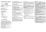
1.6 Failure Stage
Generally, how a complicated system fails is separated into three stages, initial failure, random
failure, and wear-out failure, as shown in Figure 1-3. Initial failures are considered to be removed in
the manufacturing and inspection processes of a manufacturer. Random failures are unforeseeable,
sporadic failures which occur at any time prior to the progress of wear within the useful life of
equipment, and are difficult to take technical measures. Therefore, at present, actions taken are only
based on statistics.
Wear-out failures occur at nearly the end of useful life in the course of deterioration or as a result of
wear, and increase abruptly with the elapse of time. Point tb in Figure 1-3 indicates the years when
parts will be changed. Preventive maintenance will be made appropriate by changing specific parts
for new ones at this point.
Fig.1.1 Bath-tub curve
ta
tb
0
Failure rate
Initial failure
period
Random failure period
Wear-out
failure
period
Years of use

6
2.1 Configuration of the Demonstration Machine
2
UNDERSTANDING INVERTER SYSTEM
Chapter 2 UNDERSTANDING INVERTER SYSTEM
2.1 Configuration of the Demonstration Machine
Figure 2.1 Expanded view of the inverter demonstration machine
Power
supply
1
φ
100V
NFB Tr1
MC1
TG
N
SF-JR
0.4kW 4P
%
MC2
Tr2
Load ON-OFF
R
U1 MC3
S
T
U
V
W
U
V
W
MC1
MC3
Hz
%
STF
STR
RUN
P1
P
PX
PR
TB
SU
IPF
OL
FU
A1
FM
AM
5
2
1
PCSD
FR-A720-0.75K
RES
SD
B1
C1
SE
5
10
10E
RH
RM
RL
MRS
RT
CS
SD
0V
24V
24V
0V
M
Emergency stop
Instantaneous power
failure timer
Instantaneous power
failure button
Motor phase
failure/Normal
switch
Frequency setting
Compensation input
Load torque
adjustment VR
Load torque
Powder
brake
Overheat
detection
thermal
Motor
Motor
speed

2
UNDERSTANDING INVERTER SYSTEM
2.2 External Appearance and Part Names of the Demonstration Machine
7
1
IMPORTANCE OF
PRODUCTIVE
MAINTENANCE
2
UNDERSTANDING
INVERTER SYSTEM
3
MAINTENANCE
SYSTEM DESIGN
4
PREVENTIVE
MAINTENANCE
5
BREAKDOWN
MAINTENANCE
6
CORRECTIVE
MAINTENANCE
7
REVISING
INSTALLATION
ENVIRONMENT
8
LIFE OF INVERTER
PARTS
2.2 External Appearance and Part Names of the Demonstration
Machine
The following shows the external appearance of the inverter demonstration machine.
Figure 2.2 External appearance of the inverter demonstration machine
1) FM terminal output …Displays the output frequency (pulse output) of the inverter.
2) AM terminal output …Displays the output frequency (analog output) of the inverter.
3) Running RUN ………Displayed while the inverter is running and lit when the output
frequency is equal to or higher than the starting frequency.
4) Up to frequency SU Displayed when the frequency is reached and lit when the output
frequency reaches within the range of ±10%.
5) Instantaneous power failure IPF
Displayed when the instantaneous power failure occurs and lit
when an instantaneous power failure and under voltage
protections are activated.
6) Overload OL …………A display for the warning the overload and lit when a stall
prevention is activated.
7) Frequency detection FU
Displayed when a frequency is detected and lit when the inverter
output frequency is equal to or higher than the preset detected
frequency.
8) Fault output …………Lit when the inverter protective function is activated and the output
stopped.
9) Frequency setting Terminal 2
A potentiometer for setting the frequency by analog voltage.
Load torque Motor speed FM terminal output AM terminal output
Forward rotation
STF
Reverse rotation
STR
Frequency setting
Terminal 2
Compensation
input Terminal 1
Output terminal status
Instantaneous
power failure
time setting
Load device
High speed
RH
Middle speed
RM
Low speed
RL
Running
RUN
Up to frequency
SU
Instantaneous
power failure
IPF
Overload
OL
Frequency
detection
FU
Fault
output
ABC
Overheat Thermal reset
Second function
RT
Output stop
MRS
Automatic restart
after instantaneous
power failure CS
Instantaneous power failure
Load
ON/OFF
Always turn off
the switch when
the load is OFF.
Always operate this demonstration
machine at 60Hz or less.
Inverter reset
RES
Load setting
1
3
19
20 21
22
23
24 25
26
27
28
29
Inverter FR-A720
NFB
4
910
11 12 13
14 15 16
17 18
Motor
5678
2
Operation panel
USB
Inverter demonstration machine
Emergency stop
Caution
Caution

8
2.2 External Appearance and Part Names of the Demonstration Machine
2
UNDERSTANDING INVERTER SYSTEM
10) Compensation input Terminal 1
A potentiometer for setting the voltage which add to analog
voltage of the frequency setting.
11) High speed RH …………Select "High speed" of the multi-speed setting. Up to seven
speed selections are available with combing "Middle speed"
and "Low speed".
12) Middle speed RM ………Select "Middle speed" of the multi-speed setting. Up to seven
speed selections are available with combing "High speed" and
"Low speed".
13) Low speed RL …………Select "Low speed" of the multi-speed setting. Up to seven
speed selections are available with combing "High speed" and
"Middle speed".
14) Second acceleration/deceleration RT
The second acceleration/deceleration time is selected.
15) Output stop MRS ………Stops the output of the inverter.
16) Selection of automatic restart after instantaneous power failure CS
When selecting the CS signal, the inverter restarts
automatically at power restoration (Set parameter for automatic
restart after instantaneous power failure).
17) Forward rotation STF …The forward rotation start signal.
18) Reverse rotation STR …The reverse rotation start signal.
19) Inverter reset RES ……Resets fault output provided when a fault occurs.
20) Load torque ……………Displays the load torque applied to the motor.
21) Motor speed …………… Displays the motor rotation speed.
22) Load setting ……………Set the load applied to the motor.
23) Load ON/OFF …………The ON/OFF switch of load applied to the motor.
24) Overheat ………………Lit when the load device (powder brake) to the motor is
overheated.
25) Thermal reset ………… Resets the thermal when the load device (powder brake) to the
motor is overheated.
26) Power supply NFB ……A no fuse braker for turning on the power supply of the
demonstration machine.
27) Emergency stop ………Turns off the power supply at an emergency.
28) Instantaneous power failure
Turns off of the power supply of the inverter.
29) Instantaneous power failure time setting
Set the instantaneous power failure time when pressing the
instantaneous power failure button.

2
UNDERSTANDING INVERTER SYSTEM
2.3 Precautions on Using the Demonstration Machine
9
1
IMPORTANCE OF
PRODUCTIVE
MAINTENANCE
2
UNDERSTANDING
INVERTER SYSTEM
3
MAINTENANCE
SYSTEM DESIGN
4
PREVENTIVE
MAINTENANCE
5
BREAKDOWN
MAINTENANCE
6
CORRECTIVE
MAINTENANCE
7
REVISING
INSTALLATION
ENVIRONMENT
8
LIFE OF INVERTER
PARTS
2.3 Precautions on Using the Demonstration Machine
(3) Do not leave the machine with the load ON/OFF switch turned on and the load setting VR turned
up.
(1) Set the frequency up to 60Hz.
(2) Set the acceleration/deceleration time
to one second or longer.
Although users can set the frequency to 60Hz or
more and the acceleration/deceleration time to one
second or less, it may damage devices since a
bowder brake, TG, and a timing belt are used.

10
2.4 Operating Inverter
2
UNDERSTANDING INVERTER SYSTEM
2.4 Operating Inverter
2.4.1 Operation types
A main character of inverter is that operation is enabled by various signals. This section explains the
types of operation (start, stop, and varying speed) of the inverter demonstration machine.
(1) External operation using external signal (Pr.79=0,2)
Operate an inverter with the frequency setting potentiometer or the start switch which are
connected to the control circuit terminal of the inverter.
Figure 2.3 External operation
External start or stop signal + External frequency setting signal
(STF,STR)
Frequency setting potentiometer (knob)
Contact signal (multi-speed setting)
Compensation input (knob)
IM
U
V
W
R
STF(STR)
SD
RH
RM
RL
10
2
5
1
S
T
MCNFB
FREQROL-A700
Inverter
Motor
Operation by external signal
Start, Stop
10E
Power
supply
Select
multi-speed
by switching
the contact
Frequency
setting knob
Compensation
input knob

2
UNDERSTANDING INVERTER SYSTEM
2.4 Operating Inverter
11
1
IMPORTANCE OF
PRODUCTIVE
MAINTENANCE
2
UNDERSTANDING
INVERTER SYSTEM
3
MAINTENANCE
SYSTEM DESIGN
4
PREVENTIVE
MAINTENANCE
5
BREAKDOWN
MAINTENANCE
6
CORRECTIVE
MAINTENANCE
7
REVISING
INSTALLATION
ENVIRONMENT
8
LIFE OF INVERTER
PARTS
(2) PU operation using the operation panel and the parameter unit (Pr.79=0,1)
Operate an inverter by only the operation panel or key operations or a parameter unit.
Figure 2.4 PU operation
(3) PU operation and external operation combined operation (Pr.79=3 or 4)
In the case of Pr.79=3, set the frequency from the operation panel and the parameter unit, and
input start command with the external start switch.
In the case of Pr.79=4, set the frequency from the external knob and the multi-speed, and input
start command with the operation panel and the key operation of the parameter unit.
Figure 2.5 PU/External combined operation (Pr.79=3) Figure 2.6 PU/External combined operation (Pr.79=4)
PU start signal
+
PU frequency setting signal
FWD REV
Key operation setting of PU
IM
U
V
W
R
S
T
MCNFB
FREQROL-A700
Inverter
Power
supply
Motor
Parameter unit
(FR-PU07)
Operation panel
(FR-DU07)
Option
FR-PU07
PARAMETER UNIT
MON
PrSET E XT
FUNC
SHIFT E S C
78
9
4
5
6
1
2
3
0
READ
WRITE
FWD
REV
STOP
RESET
MITSUBISHI
POWER
ARARM
PU
Operation using the operation panel or
the parameter unit
+
PU frequency setting
Motor
Three-phase
AC power
supply
Inverter
R/L1
S/L2
T/L3
U
V
W
FR-DU07
STR
STF
SD
Set frequency
+
External frequency
setting signal
FWD
REV
3
4
5
6
7
8
9
10
Hz
Motor
Inverter
R/L1
S/L2
T/L3
U
V
W
5
10
2
FR-DU07
,
External start or stop
signal (STF, STR)
Key operation setting of PU
Forward
rotation start
Reverse
rotation start
PU start or stop signal
Three-phase
AC power
supply
Frequency
setting
potentiometer

12
2.5 How to Use Operation Panel FR-DU07
2
UNDERSTANDING INVERTER SYSTEM
2.5 How to Use Operation Panel FR-DU07
2.5.1 Basic operation
At power-ON (External operation mode)
PU operation mode
(output frequency monitor)
Parameter setting mode
PU Jog operation mode
Output current monitor
Output voltage monitor
Display the present
setting
Value change
Value change
Parameter write is completed!!
Parameter and a setting value
flicker alternately.
Parameter clear All parameter
clear
Faults history clear
Parameter copy
(Example)
(Example)
Frequency setting has been
written and completed!!
and frequency flicker.
[Operation for displaying faults history]
Past eight faults can be displayed.
(The latest fault is ended by ".".)
When no fault history exists, is displayed.
Operation mode switchover
Parameter setting
Faults
history
Monitor/frequency setting

2
UNDERSTANDING INVERTER SYSTEM
2.5 How to Use Operation Panel FR-DU07
13
1
IMPORTANCE OF
PRODUCTIVE
MAINTENANCE
2
UNDERSTANDING
INVERTER SYSTEM
3
MAINTENANCE
SYSTEM DESIGN
4
PREVENTIVE
MAINTENANCE
5
BREAKDOWN
MAINTENANCE
6
CORRECTIVE
MAINTENANCE
7
REVISING
INSTALLATION
ENVIRONMENT
8
LIFE OF INVERTER
PARTS
2.5.2 Setting parameters
As an example of changing parameter setting value, this section explains how to change the setting
value of Pr.1 Maximum frequency from 120Hz to 60Hz.
Press the setting dial M ( ) to display the current set frequency.
1.
Screen at power-ON
The monitor display appears.
Display
Operation
3.
Press to choose the parameter
setting mode.
4.
Turn until (Pr. 1)
appears.
u
ears
Flicker...Parameter setting is completed!!
7.
Press to set.
6.
Turn to change it to the
setting value " ".
c
[PU] indicator is lit.
2.
Press to choose the PU
operation mode.
· By turning , you can read another parameter.
· Press twice to show the next parameter.
· Press to show the setting again.
The parameter
number read
previously appears.
5.
Press to read the present set
value.
" " (initial value) appears.
· Press twice to return the monitor to frequency monitor.

14
2.5 How to Use Operation Panel FR-DU07
2
UNDERSTANDING INVERTER SYSTEM
2.5.3 All parameter clear
Set "1" in ALLC All parameter clear to initialize all parameters.
(Parameters are not cleared when "1" is set in Pr. 77 Parameter write selection.)
1.
Screen at power-ON
The monitor display appears.
[PU] indicator is lit.
Display
Operation
The parameter
number read
previously appears.
2.
Press to choose the PU
operation mode.
3.
Press to choose the parameter
setting mode.
4.
Turn until
(all parameter clear) appears.
u
5.
Press to read the present set
value.
" " (initial value) appears.
6.
Turn to change it to the
setting value " ".
c
7.
Press to set.
Flicker...Parameter setting is completed!!
· By turning , you can read another parameter.
· Press twice to show the next parameter.
· Press to show the setting again.

2
UNDERSTANDING INVERTER SYSTEM
2.5 How to Use Operation Panel FR-DU07
15
1
IMPORTANCE OF
PRODUCTIVE
MAINTENANCE
2
UNDERSTANDING
INVERTER SYSTEM
3
MAINTENANCE
SYSTEM DESIGN
4
PREVENTIVE
MAINTENANCE
5
BREAKDOWN
MAINTENANCE
6
CORRECTIVE
MAINTENANCE
7
REVISING
INSTALLATION
ENVIRONMENT
8
LIFE OF INVERTER
PARTS
2.5.4 Parameter copy
Parameter setting values for one inverter can be copied to two or more inverters.
● Connect it during a stop.
6. Press to copy the source
parameters to the operation panel.
4. Press to read the currently set value.
" " (initial value) appears.
9. Press to write the parameters
copied to the operation panel to the
destination inverter.
3. Turn until " "
(parameter copy) appears.
flickers for about 30s
After about 30s
flickers for about 30s
10. " " and " " flicker alternately
after parameters are copied.
11. After writing the parameter values to the
copy destination inverter, always reset
the inverter, e.g. switch power off once,
before starting operation.
7. Connect the operation panel to the
copy source inverter.
8. After performing steps 2 and 5,
turn to change it to " ".
Display
Operation
1.
Screen at power-ON
The monitor display appears.
2. Press to choose the parameter
setting mode.
The parameter
number read
previously appears.
5. Turn to change it to the
setting value " ".
c
Flicker...Parameter copy is completed!!
Flicker...Parameter copy is completed!!
/