Page is loading ...

1
Installation Manual
Entryway Arbor Kit
Single-Wide: 3 High & 4 High Panel Assemblies
PLAN VIEW FOR FRONT COVER
3'-7"
1'-8"
Yardistry - North America
Toll Free Customer Support: 1.888.509.4382
www.yardistrystructures.com
Yardistry / Selwood Products - Europe
Customer Support: +44 1284 852569
www.selwoodproducts.com
Revised 05/22/2012

2
!Important Safety Notice!
• Yardistry components are intended for privacy, decorative and ornamental use only. Product is NOT
INTENDED for the following:
- A safety barrier to prevent unsupervised access to pools, hot tubs, spas, or ponds.
- Safety railings for elevated platforms or decks.
- As load bearing support for a building, structure, heavy objects or swings. - Used in structures that trap
wind, rain or snow that would create extra load on the product.
• Permanent structures may require a building permit. As the purchaser and or installer of this product you
are advised to consult local planning, zoning, and building inspection departments for guidance on applicable
building codes and or zoning requirements.
• Wood is NOT ame retardant and will burn. Grills, re pits and chimneys are a re hazard if placed too
close to a Yardistry structure. Consult user’s manual of the grill, re pit or chimney for safe distances from
combustible materials.
• During installation, follow all safety warnings provided with your tools and use OHSA approved safety
glasses.
• Some structures may require two or more people to install safely. Check for underground utilities
before digging or driving stakes into the ground!
General Information: Wood components are manufactured with Cedar (C. Lanceolata) which is protected with
factory applied water-based stain. Knots, small checks (cracks) and weathering are naturally occurring and do
not affect the strength of the product. Annual application of a water-based water repellent sealant or stain will help
reduce weathering and checks.
Warranty: Yardistry products are backed by a 5 year limited lifetime warranty from the date of original retail
purchase for manufacturing defects and if installed as per manufacturer’s installation instructions.
Patents Pending
Part Identification Key
On each page, you will find the parts and
quantities required to complete the assembly
step illustrated on that page. Here is a sample.
Symbols
Throughout these instructions symbols are provided as important reminders for proper and safe assembly.
Proper Hardware Assembly
Lag screws require drilling pilot
holes to avoid splitting wood. Only
a flat washer is required. For ease of
installation liquid soap can be used
on all lag-type screws.
For bolts, tap T-Nut into hole with
hammer. Insert the hex bolt through
lock washer first then flat washer then
hole. Because the assemblies need to
be squared do not completely tighten
until instructed. Pay close attention to
diameter of the bolts. 5/16” is slightly
larger than 1/4”.
Note: Wafer head bolts with blue lock
tight or a bolt with a Ny-Lok nut do
NOT require a lock washer.
Once the assembly is tightened, watch for exposed
threads. If a thread protrudes from the T-Nut, remove
the bolt and add washers to eliminate this condition.
Extra washers have been provided for this purpose.
This identifies information that requires special
attention. Improper assembly could lead to an
unsafe or dangerous condition.
Where this is shown, 2 or 3
people are required to safely
complete the step. To avoid
injury or damage to the
assembly make sure to get help!
Check that assembly is square
before tightening bolts.
Use a measuring tape to assure
proper location.
Check that set or assembly is properly level
before proceeding.
Pre-drill a pilot hole
before fastening screw
or lag to prevent
splitting of wood.
This indicates time to tighten bolts, but
not too tight! Do not crush the wood.
This may create splinters and cause
structural damage.
Use
Help
Use
Help
Measure
Distance
Square
Assembly
Use
Level
Pre-drill 1/8” & 3/16” Bit
Tighten
Bolts
No Yes
CAUTION – Protrusion Hazard
6
Keys to Assembly Success
Tools Required
• Tape Measure
• Carpenters Level
• Carpenters Square
• Claw Hammer
• Standard or Cordless Drill
• #1, #2 & #3 Phillips
or Robertson Bits
or Screwdriver
• Ratchet with extension
(1/2” & 9/16” sockets)
• Open End Wrench
(7/16”, 1/2” & 9/16”)
• Adjustable Wrench
• 1/8” & 3/16” Drill Bits
• Pencil
• 3/16” Hex Key
• 8’ Step Ladder
• Safety Glasses
• Adult Helpers
Quantity Key Number Part Description, Part Size
2X A1 Post 2 x 4 x83”
Use an extra
Flat Washer
If Bolt protrudes
beyond T-Nut
Lag Screw
Flat Washer
Lag Assembly
Before mounting Lag Screw,
use factory drilled holes as
guides to drill 1/8” pilot holes
Hex Bolt
Bolt Assembly
T-Nut
(Hammer into place)
Do not crush wood!
Lock
Washer
Flat
Washer
Keys To Assemble Success
• Tape Measure
• Carpenters Level
• Carpenters Square
• Standard or Cordless
Drill
• #2 Phillips or Robertson
Bits or Screwdriver
• Ratchet with extension
(7/16” sockets)
• Open End Wrench
(7/16”)
• Adjustable Wrench
• 1/8” Drill Bit
• Pencil
• 1/4” Drill Bit
• 8’ Step Ladder
• Safety Glasses
• Adult Helpers
Tools Required

3
(36) #10 x 1"
S1
(2) 2 x 4 x 80"
Y50113-029
A
Y50113-030
C
(6) 5/4 x 3 x 54¼"
4 x 4 Post Top Connector
YP21012
(vendu séparément)
(sold separately)
(se vende por separado)
YP11011
4 x 4 x 96" Post
YP11012
2 x 4 Beam End
1½" x 3½"
Actuel
1" x 2½"
Nominale
5/4" x 3"
2" x 4"
(12) 5/4 x 3 (Y70813-000)
(2) 2 x 4 x 41ǩ"
Y50113-031
B
4 x 8 Arbor Roof Kit includes:
3
Conectores superiores
de postes de 4 x 4
Attaché a Poteau 4 x 4 po.
Kit de techo de la pérgola de 4" x 8" incluye:
Kit de Toit Arbor 4 x 8 po inclus:
Postes de 4 x 4 x 96"
Poteau 4 x 4 x 96 po.
Extremos de viga de 2' x 4'
Poteau d’extrémité 2 x 4 po.
Material List
S4
S7
S5
S6
S4
S7
S5
S6
S4
S7
S5
S6
S4
S7
S5
S6
S4
S5
S6
#8 x 2 1/4” Wood Screw
#10 x 1” Pan Head Screw
S7
#10 x 1 1/2” Pan Head Screw
#8 x 1 1/2” Wood Screw
B > 24"
(90"- 96")
C
A = B+C
Post must be securely
installed to support structure.
Consult local building
codes and ground conditions
for required footing design.
El poste debe instalarse
firmemente para sostener
la estructura. Consulte
los códigos o leyes de
construcción locales y las
condiciones del suelo
para el diseño del cimiento
requerido.
Les poteau doivent être
installés solidement pour
soutenir la structure.
Consultez les codes du
bâtiment locaux et les
conditions du sol pour
concevoir adéquatement la
semelle.
Pour déterminer la longueur
des poteaux, utilisez cette
formule:
Para determinar los
requerimientos de
longitud de los postes,
utilice la siguiente
fórmula:
To determine post length
requirements, use this formula:
A
Cut - Corte - Couper
Vérifiez la présence d'installations de
services publics souterraines avant de
creuser ou d'enfoncer des piquet dans
le sol!
Check for underground
utilities before digging or
driving stakes into the
ground!
¡Verifique la ubicación de las tuberías
subterráneas antes de excavar o de
clavar estacas en el suelo!
!
Post Heights - Altura de los postes - Hauteur des poteau
(90"- 96")
4 x 4 Posts and Post Top Connectors (sold separately)
4 x 4 Postes y el conector superior de poste (se vende por separado)
4 x 4 Poteau en le connecteur de bout de poteau (vendu séparément)
4 x 4 Post Top Connector
4 x 4 Post
4
4 x 4 Poteau
4 x 4 Postes
4 x 4 conector superior de poste
4 x 4 connecteur de bout de poteau
WH
(4) Post Top Connector With
7/16” Hex Bolt Assembly
(12) Panel Clips
R
(4) Top and Bottom Rail - 20”
BE
(8) 2x4 Beam Ends
2 x 4 x 25”
5/4 x 3 x 35 3/4”
2 x 4 x 44 1/2”
#10 x 1” Pan Head Screw Gray
Nominal
Actual

4
Material List
P
(4) 4x4 Post
(4) 2 x 4 x 12” Gusset
G
*Optional- May Not
be Included
(4) 2 x 6 x 36-13/16"
B
Y50113-034
2x3
(22) 2 x 3 (Y70813-001)
(42) 1/4" x 2"
(44) #10 x 1"
1½" x 2½"
Actuel
1½" x 5½"
2" x 3"
1" x 6"
2" x 6"
ǫ" x 5½"
Nominale
(64) 1/4"
S1
WT
(20) 1/4"
WL
(22) 1/4"
S3
(34) #8 x 3½"
(22) 2 x 3 x 34¾"
H
Y50113-035
(4) 2 x 6 x 37"
C
Y50113-036
(4) 2 x 6 x 13½"
A
Y50113-020
S2
(8) #8 x 1½"
(4) 2 x 6 x 21ǫ"
F
Y50113-022
(4) 2 x 6 x 80ǩ"
G
Y50113-024
(2) 1 x 6 x 80½"
E
Y50113-032
(11) 2 x 3 x 83½"
I
Y50113-033
(4) 2 x 6 x 81Ǭ"
D
Y50113-037
2
(8) #8 x 3” Wood Screw
Single Wide Entry Arbors
3 High X / Arch Assembly - YM11576
3 High X Assembly- YM11570
3 High Lattice / X Assembly - YM11574
3 High Lattice Assembly - YM11572
4 High X / Arch Assembly - YM11577
4 High X Assembly - YM11571
4 High Lattice / X Assembly - YM11575
4 High Lattice Assembly - YM11573
4 High / Faux Panel - YM11606
Note: Panel assembly in this instruction is
shown as a 3 High X Panel or 3 High Lattice
Panel with a 1 High X Topper. Depending on
kit purchased, images may not be accurate.
Please see front cover for what your nal
set-up should look like.
P_1
P_3
(2) Two/Three High X Panel or,
(2) Two/Three High Lattice Panel
(2) One High X Topper or,
(2) One High Lattice Topper or,
(2) One High Arch Topper

5
2x One High _ Topper
2x Three High _ Panel
4x Top & Bottom Rail
8x #8- 2 1/4” Wood Screws
R
R
Step 1- Assemble Panels
Fig. 1A
Secure with Screws*. Use factory drilled holes.
Asegure el ensamblado usando tornillos*.
Use los agujeros pretaladrados.
Fixez l'assemblage au moyen de vis*. Servez-
vous des trous prépercés à l'usine.
empêche l'accumulation d'eau.
Note wood piece at bottom
prevents collection of water.
Note que la pieza de madera
inferior evita la acumulación de
agua.
Prenez note que la pièce en bois
située au bas de chaque
élément de l'assemblage
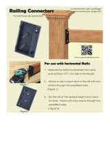
Do not remove Small Connector.
No retire los conectores
Ne retirez pas les petites pièces de
raccordement.
1
Assemble Panels in the required orientation for your project.
*Hardware is provided with 2x2x62" post/rail.
Unir los paneles según la orientación necesaria para su proyecto.
l'usine.
supérieurs du panneau qui ont été percés à
A.
fixez-les de nouveau au moyen des deux trous
*Máximo 3 paneles de ancho x 3 paneles de alto.
*Se proporcionan los artículos de ferretería con los postes/travesaños de 2x2x62".
*Maximum 3 panel wide x 3 panel high.
*Le matériel est fourni avec 2x2x62" poste/barre.
*Le maximum 3 panneau x large 3 lambrisent haut.
Assembler Panneau dans l'orientation exigée pour votre projet.
Remove Large Connectors and reattach using
top two factory drilled holes on panel.
Retire los conectores grandes y vuelva a
instalarlos usando los dos agujeros
pretaladrados del panel.
Retirez les grandes pièces de raccordement et
Assemble Toppers to Panels if required.
Instale los topes en los paneles.
Assemblez les pièces supérieures et les panneaux dans l'orientation exigée pour votre projet.
Note orientation of keyhole.
Tenga en cuenta la orientación
del agujero de la cerradura.
Notez l'orientation de l'encoche
en trou deserrure.
2
Fig. 1B - Filler Strips on Bottom
of Panel!
1. Remove the upper metal connectors on both sides of P_3 - Three High Panel. Reattach the metal connectors
to P_3 by securing the bottom two holes of the metal connectors to the top two holes on P_3 so that the metal
connectors stick out from the top. Slide P_1 – One High Topper between the two protruding metal connectors
on the top of P_3. Attach the metal connectors to P_1.” (Fig. 1A) *Ensure Panels are oriented correctly!
(Fig. 1B)
x2
R
P_3
P_1
+ =
3. Connect last assembled panels to make a fence section.
Cut and attach Top and Bottom Rails.
Corte y fije los rieles superior e inferior.
Taillez et fixez la main courante ainsi que la lisse basse.
Insert male into female. Slide down until flush with adjacent panel.
Introduzca el extremo macho en el extremo hembra. Deslícelo hacia
abajo hasta que quede al ras del panel adyacente.
Insérez les pièces de raccordement mâles dans les pièces
de raccordement femelles. Faites glisser le panneau
vers le bas jusqu'à ce qu'il soit au même niveau que
le panneau adjacent.
Remove Large Connectors and reatta
ch using top two
factory drilled holes on panel.
Retire los conectores grandes y vuelva a instalarlos
usando los dos agujeros pretaladrados del panel.
Retirez les grandes pièces de raccordement et fixez-les
de nouveau au moyen des deux trous
supérieurs du panneau qui ont été percés
à l'usine.
Note
orientation
of keyhole.
Tenga en cuenta
la orientación del
agujero de la
cerradura.
Notez l'orientation
d
e l'encoche en
trou de serrure.
Note que la pieza de madera inferior
evita la acumulación de agua.
Top and Bottom Rail will
overhang 1/4"on either side.
Attach Top with Screws*
through factory drilled holes.
On Bottom, space Screws*
4" from edges of panels.
Shown here are configurations using
a Topper. 2 and 3 High Panels can
also be connected together as
purchased.
*Use 2 1/4" stainless steel screws
included in the Panel Clip set to
secure and strengthen the assembly.
1/4"
1/4"
1/4"
1/4"
78
½"
59"
20" 20" 20" 20"
39
½"
39
½"
One Wide Ancho sencillo Une pièce de largeur
Four Wide Ancho cuádruple Quatre pièces de largeur
Three Wide Ancho triple Trois pièces de largeur
Two Wide Ancho doble Deux pièces de largeur
2
Assemble Panels side by side.
Conecte los paneles lado a lado.
Assemblez les panneaux côte à côte.
No retire los conectores
pequeños.
Note wood piece at bottom prevents
collection of water.
Prenez note que la pièce en bois
située au bas de chaque élément
de l'assemblage empêche
l'accumulation d'eau.
Secure with Screws*. Use factory drilled holes.
Ne retirez pas les petites pièces
de raccordement.
Do not remove Small Connectors.
Fixez l'assemblage au moyen de vis.* Servez-vous des trous prépercés à l'usine.
Asegure el ensamblado usando tornillos*. Use los agujeros pretaladrados.
Screws* are 2 1/4" stainless
steel included in Panel Clip set.
Los tornillos* son de acero inoxidable de 2 1/4"
y se incluyen en el juego de sujetadores de paneles.
*Les
vis sont celles de 2-1/4 po en acier inoxydable qui sont fournies dans le nécessaire de fixations pour panneaux.
Basic Guidelines
for Panel Assembly
Las ilustraciones muestran
configuraciones con topes. También
se pueden conectar 2 y 3 paneles
altos a medida que se adquieran.
*Use los tornillos de acero inoxidable
de 2 1/4" que se incluyen en el juego
de sujetadores de paneles para
reforzar el ens
amblado.
Pautas básicas para
el ensamblado de
los paneles
Les assemblages illustrés comportent des
pièces supérieures. Il est possible
également d'assembler des panneaux
à deux ou à trois carreaux de hauteur
(vendus séparément).
*Utilisez les vis en acier inoxydable de
2-1/4 po fournies dans le nécessaire de
fixations pour panneaux afin de fixer et
de renforcer l'assemblage.
Instructions de base
pour
l'assemblage
des panneaux
1
Assemble Toppers to Panels.
Instale los topes en los paneles.
Assemblez les pièces supérieures
et les panneaux.
3
Los rieles superior e inferior sobresaldrán 1/4"
a cada lado. Fije el tope instalando tornillos*
en los agujeros pretaladrados. En la parte
inferior, deje un espacio de 4" entre los
tornillos* y los bordes de los paneles.
}
4"
}
4"
}
4"
}
4"
La main courante et la lisse basse seront
en surplomb de 1/4 po de chaque côté.
Fixez la main courante en insérant les vis*
dans les trous prépercés à l'usine. Au bas
des panneaux, laissez un espace de 4 po
entre les vis et les côtés des panneaux.
panel_cap_labels_19x9.5.indd 7 12/3/09 4:17:29 PM
P_1
P_3
S4
2. Secure panels with a S4 - 2 1/4” Wood
Screw the location indicated by the large
arrow in the direction of the arrow.
3. Secure R-Top and Bottom Rails to Panel
Assembly with S4 - 2 1/4” Wood Screws
locations indicated by small arrows in
the direction of the arrow. *R- Top and
Bottom Rails will overhang 1/4” on
either side of panel.
4. Repeat until two panel assemblies are
created.
Pilot holes to the right
2x Top & Bottom Rail at 7 1/4” (18.4 CM)
***If you have purchased YM11576 or YM11577,
cut to size to accommodate the arch topper.
R

6
4x 4x4 Post 12x - Panel Clips
24x #8 x 1 1/2” Wood Screw
P
S7
Step 2- Attach Panel Clips to posts
3 High Panel Assembly
(4 high panel Assembly instruction located on next page)
1. On a at surface place P- 4x4 Post on its side and position Panel Clips in locations indicated in Figure 1.
Ensure Panel Clips are oriented as shown in Diagrams!
2. Panel Clips should be placed in the centre of the post or the leading edge of the clip should be 1 3/8” or
3.5cm away from the side of the post as shown in Fig. 2.
3. With Panel Clips in place, mark screw holes with a pencil and pre-drill holes with a 1/8” drill bit. (Not
provided)
4. Secure Panel Clips in locations indicated in gure 1 and 2 with S7 - #8 x 1 1/2” wood screws.
5. Repeat for each post conguration (2 in total).
Fig. 1
1 3/8”
Fig. 2
Pre-drill holes and secure with S7- #8 x
1 1/2” Wood Screws
(3.5cm)
A
1. On a at surface place P- 4x4 Post on its side and position Panel Clips in
locations indicated in Figures 1 and 1A. Ensure Panel Clips are oriented
as shown in Diagrams!
2. Panel Clips should be placed in the centre of the post or the leading edge
of the clip should be 1 3/8” or 3.5cm away from the side of the post as
shown in Fig. 2.
3. With Panel Clips in place, mark screw holes with a pencil and pre-drill
holes with a 1/8” drill bit. (Not provided)
4. Secure Panel Clips in locations indicated in gure 1 and 1A with S7- #8 x 1
1/2” wood screws.
Front View
B
C
D
Top View
(142.9cm)
(25.3cm)
56 1/4”
40”
(101.6cm)
Top View
A B C D

7
4x 4x4 Post 12x - Panel Clips
24x #8 x 1 1/2” Wood Screw
P
S7
1. On a at surface place P- 4x4 Post on its side
and position Panel Clips in locations indicated
in Figure 1. Ensure Panel Clips are oriented
as shown in Diagrams!
2. Panel Clips should be placed in the centre of
the post or the leading edge of the clip should
be 1 3/8” or 3.5cm away from the side of the
post as shown in Fig. 2.
3. With Panel Clips in place, mark screw holes
with a pencil and pre-drill holes with a 1/8” drill
bit. (Not provided)
4. Secure Panel Clips in locations indicated
in gure 1 and 2 with S7- #8 x 1 1/2” wood
screws.
5. Repeat for each post conguration (2 in total).
Front View
Fig. 1
A B
C D
1 3/8”
Fig. 2
Pre-drill holes and secure with S7- #8 x
1 1/2” Wood Screws
(3.5cm)
(190.5cm)
(101.6cm)
(25.3cm)
75”
40”
Step 2- Attach Panel Clips to posts
4 High Panel Assembly
Top View

8
STEP 3 -Attach Panels to Posts
STEP 3 -Attach Panels to Posts
12x 1” Pan Head Screw
S5
Step 3 -Attach Panels to Posts
1. Place panel assemblies on posts as shown (Fig.1) allowing a 4” gap between the bottom of the post and the
bottom edge of the bottom rail on the panel assembly. Note: Assemble with help of another adult.
2. With a 1/8” drill bit, predrill holes as shown in gure 2.
3. Fasten the panel assembles to the post and Panel Clips with a S5- 1” Pan Head Screw provided in location of
arrows. (Fig. 1)
4. Repeat for each post conguration.
x2
Fig. 1
Fig. 2. Predrill Holes and Fasten
with S5- 1” Pan Head Screw
STEP 3 -Attach Panels to Posts
4” (10.2cm)
3 High
4 High
4” (10.2cm)

9
16x 1 1/2” Pan head Screws
4x - Post Top Connector
STEP 4 -LAYOUT POSTS AND CONNECTORS
S6
Step 4- Layout Posts and
Connectors
78½"
78½"
78½"
20"
78½"
20"
20"
20" 20"
20"
20"
20"
132½"
177
"177 "
1
Install 4x4 Posts and 4x4 Post Top Connectors.
Spacing between 4x4 Posts and direction of 4x4 Post Top Connectors is critical.
5
Installer le Poteau 4 x 4 po et le Connector de Poteau 4 x 4
po.
L’espace entre Poteau 4 x 4 po et la direction de Poteau
connecteur et critical.
Coloque los postes de 4x4 y los conectores superiores
de postes de 4x4. El espacio entre los postes de 4x4 y
la
dirección de los conectores superiores de postes de
4x4
es crucial.
Fig. 1
Fig. 2 - Attach Post Top Connectors
with S6- 1 1/2” Pan Head Screws.
1. Layout Arbor bases in conguration shown in gure 1. **Posts must be securely installed
to support structure. Consult local building codes and ground conditions for required
footing design. It is recommended the structure be secured to existing stone, concrete or
deck with the Yardistry Post Base (YM21016) or equivalent hardware.
2. Install Post Top Connectors with S6- 1 1/2” Pan Head Screws provided. (Fig. 2) Ensure the
direction of the Post Top Connector is the same direction as indicated by the arrows in gure 1.
Install on a at
and level surface!
Part Identification Key
On each page, you will find the parts and
quantities required to complete the assembly
step illustrated on that page. Here is a sample.
Symbols
Throughout these instructions symbols are provided as important reminders for proper and safe assembly.
Proper Hardware Assembly
Lag screws require drilling pilot
holes to avoid splitting wood. Only
a flat washer is required. For ease of
installation liquid soap can be used
on all lag-type screws.
For bolts, tap T-Nut into hole with
hammer. Insert the hex bolt through
lock washer first then flat washer then
hole. Because the assemblies need to
be squared do not completely tighten
until instructed. Pay close attention to
diameter of the bolts. 5/16” is slightly
larger than 1/4”.
Note: Wafer head bolts with blue lock
tight or a bolt with a Ny-Lok nut do
NOT require a lock washer.
Once the assembly is tightened, watch for exposed
threads. If a thread protrudes from the T-Nut, remove
the bolt and add washers to eliminate this condition.
Extra washers have been provided for this purpose.
This identifies information that requires special
attention. Improper assembly could lead to an
unsafe or dangerous condition.
Where this is shown, 2 or 3
people are required to safely
complete the step. To avoid
injury or damage to the
assembly make sure to get help!
Check that assembly is square
before tightening bolts.
Use a measuring tape to assure
proper location.
Check that set or assembly is properly level
before proceeding.
Pre-drill a pilot hole
before fastening screw
or lag to prevent
splitting of wood.
This indicates time to tighten bolts, but
not too tight! Do not crush the wood.
This may create splinters and cause
structural damage.
Use
Help
Use
Help
Measure
Distance
Square
Assembly
Use
Level
Pre-drill 1/8” & 3/16” Bit
Tighten
Bolts
No Yes
CAUTION – Protrusion Hazard
6
Keys to Assembly Success
Tools Required
• Tape Measure
• Carpenters Level
• Carpenters Square
• Claw Hammer
• Standard or Cordless Drill
• #1, #2 & #3 Phillips
or Robertson Bits
or Screwdriver
• Ratchet with extension
(1/2” & 9/16” sockets)
• Open End Wrench
(7/16”, 1/2” & 9/16”)
• Adjustable Wrench
• 1/8” & 3/16” Drill Bits
• Pencil
• 3/16” Hex Key
• 8’ Step Ladder
• Safety Glasses
• Adult Helpers
Quantity Key Number Part Description, Part Size
2X A1 Post 2 x 4 x83”
Use an extra
Flat Washer
If Bolt protrudes
beyond T-Nut
Lag Screw
Flat Washer
Lag Assembly
Before mounting Lag Screw,
use factory drilled holes as
guides to drill 1/8” pilot holes
Hex Bolt
Bolt Assembly
T-Nut
(Hammer into place)
Do not crush wood!
Lock
Washer
Flat
Washer
3’ 7”
3’ 11-1/2”

10
36x #10- 1” Pan Screw Gray
12x -5/4 x 3” Bracket
32x 7/16” Hex Bolt w/ Nut
2x 2 x 4 x 41” Beam
2x 2 x 4 x 25” Beam
8x 2 x 4 Beam Ends
6x 5/4 x 3 x 35 1/4” trellis
Z
Step 5- Assemble Roof
A
B
WH
C
S1
1. Attach two A- 2 x 4 x 44-1/2” Beams to Post Top Connectors with WH-7/16" Hex Bolt as shown in Fig. 1 and 1A.
2. Centre two B-2 x 4 x 25” Beams in place and attach to Post Top Connectors with WH-7/16" Hex Bolt as shown
in Fig. 1 and 1A. Drill 1/4” Holes for bolts using holes in Post Top Connector as guides.
3. Attach eight BE- 2 x 4 Beam Ends to Post Top Connectors with WH-7/16” Hex Bolt as shown in Fig. 1 and 1A.
4. Evenly space apart and secure six C-5/4 x 3 x 35 3/4” Trellis to Beams using 5/4 x 3” Brackets and S1 #10- 1”
Pan Screw Gray as shown in gures 1 and 2.
STEP 5 -Assemble Roof
STEP 5 -Assemble Roof
Fig. 1
Fig. 1A
BE
BE
Fig. 2
BE
Drill 1/4” Holes for bolts using
holes in Post Top Connector as
guides.
STEP 5 -Assemble Roof
A
B
5/4 x 3”
S1
BE
A
B
BE
A
B
C
C
(1.09m)
3’ 7”
/