Page is loading ...

IR T1
Small Area Infrared Transmitter
USER MANUAL
MAN 212F

IR T01 Small Area Infrared Transmitter
Important Safety Instructions
Please read and keep these instructions.
WARNING! To reduce the risk of fire or electric shock, do not expose the system
to rain or moisture. Do not use this apparatus near water. The system should
not be exposed to dripping or splashing, and objects filled with liquids such as
beverages should not be placed on the transmitter or receivers. Clean only with
a dry cloth.
Attempting to service this device will void the warranty
• Refer servicing to qualified personnel. Servicing is required when the system
has been damaged in any way: if liquid has been spilled or objects have fallen
into the unit, if the unit has been exposed to moisture, if the unit does not
operate normally, or if the unit has been dropped.
• Do not block any ventilation openings. Install in accordance with
manufacturer’s instructions.
• Do not install near any heat sources such as radiators, heat registers,
stoves, or other apparatus that produces heat.
• Use only attachments/accessories specified by the manufacturer.
• Unplug the transmitter during lightning storms or when unused for long periods of
time.
• Be advised that dierent operating voltages require the use of dierent
attachment plugs. Check the voltage in your area and use the correct type.
• Use only the power supply provided by Williams AV. Other power supplies
may have similar specifications, but may not be equivalent in emissions
ratings, in-rush current, etc. Use of an unapproved power supply may leave
the device partially or completely inoperable, and will void the warranty.
• Protect the power cord from being walked on or pinched, particularly at
plugs, receptacles, and near the power jack on the transmitter.
• This apparatus must be grounded.
• The AC Power plug or an appliance coupler is used as the disconnect
device, so the disconnect device should remain readily operable.
For Customers in The United States
This equipment has been tested and found to comply with the limits for Class B
digital device, pursuant to part 15 of the FCC rules.
For Customers in Canada
This Class B digital device meets all requirements of the Canadian Interference-
causing Equipment Regulations. Cet appareil numérique de la classe B respecte
toutes les exigencies du Règlement sur le matériel brouilleur du Canada.

IR T01 Small Area Loop Infrared Transmitter
Recycling Instructions
Please help Williams AV protect the environment. Please take the time to dispose
of your equipment properly.
Product Recycling for Customers in the European Union:
Please do NOT dispose of your Williams AV equipment in the household
trash. Take the equipment to a electronics recycling center, or return the
product to the factory for proper disposal.
System Overview
The IR T1 is a two-channel infrared transmitter combining infrared modulator and
emitter technology into a single mountable enclosure—which reduces operating
costs, eliminates the need for rack space and eases set-up.
The IR T1 is ideal for high quality audio programs such as music, television audio,
and audio description. The IR T1 will accept any line level stereo audio input.
Infrared receivers detect the transmission and convert the light signals back
into audio signals. The IR T1 operating frequencies (2.3/2.8 MHz) minimize high
eciency lighting interference.
No FCC license or radio approval is required with this equipment. It can be used
anywhere in the world.
NOTE: This equipment has been tested and found to comply with the limits for
a Class B digital device, pursuant to part 15 of the FCC Rules. These limits are
designed to provide reasonable protection against harmful interference when the
equipment is operated in a commercial environment. This equipment generates,
uses, and can radiate radio frequency energy and, if not installed and used in
accordance with the instruction manual, may cause harmful interference to radio
communications. Operation of this equipment in a residential area may cause
interference, in which case the user will be required to correct the interference at
his own expense.
NOTE: A PLASMA MONITOR OR TELEVISION CAN DEGRADE THE AUDIO QUALITY
OF THE IR T1 TRANSMITTER. FOR BEST PERFORMANCE, THE TRANSMITTER
SHOULD BE POSITIONED AS FAR AWAY AS POSSIBLE FROM ANY PLASMA
MONITOR, TELEVISION OR OTHER INTERFERING DEVICES.
Installation Procedures
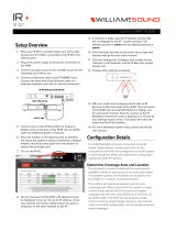
Determine Coverage Area
When using the IR T1 transmitter with the RX22-4 receiver, the system coverage
area will exceed 1000 sq. ft. (93 sq. m.). Figure 1 illustrates typical coverage pattern
for the IR T1. This can be aected by direct/indirect sunlight, reflections on walls,
objects in the room and room construction. The patterns illustrated are the direct
radiation pattern. Most objects block infrared light, so the transmitter cannot be
concealed behind walls, glass, curtains, etc. The infrared radiation does not drop to
zero outside the illustrated patterns; it decreases. It still may be useable at a greater
distance, depending on the receiver sensitivity and the reflective characteristics of
the room.
Important: Remember to point the transmitter towards the listening audience. The front
is the surface with the Williams AV logo as shown on the cover of this manual.
See Figure 1.

IR T01 Small Area Infrared Transmitter
Figure 1 - IR T1 Coverage Pattern
Connections & Indicators
Figure 2 - IR T1 Rear View
Power In
Power Indicator
(Green)
3.5mm Audio Line Input
Audio Indicator (Ch.1)
(Yellow)
Audio Indicator (Ch.2)
(Yellow)
5VDC 0.2A
IR T1 INFRARED TRANSMITTER
2.3 MHz
LINE IN
2.8 MHz
Connecting Power
1. Snap in the correct adapter for your region into the TFP 055 power supply.
2. Plug the USB end of the “USB to micro USB cord” into the power supply.
3. Plug the micro USB end of the “USB to micro USB cable” into the IR T1.
4. Plug the power supply into an AC outlet.
Alternatively, you may plug the USB end of the cord into a direct USB power
source, such as the USB port on a television, etc. to power the IR T1.
On power up, the IR T1 performs a self-test to detect damage due to shipping,
handling, tampering or incorrect operation. If any failure is present, the green
power LED will blink rapidly. If this occurs, contact Williams AV Customer Service.
This system is designed for class 2, low-voltage wiring. Always follow local
electrical codes when using low-voltage wiring.

IR T01 Small Area Loop Infrared Transmitter
Audio Indicators (Ch. 1,2)
The audio indicator LEDs (see Figure 2) will light up yellow when an adequate
level of input audio is sensed on that channel. If audio is present, but not high
enough to produce acceptable audio quality, the LED will not light. Once an
adequate level of audio is fed to the unit, the LED will stay on. If the audio level
falls below the acceptable threshold, the LED will go out, and the sleep timer will
start to turn o that channel after approximately 12 minutes (See “Sleep Mode”
below).
Sleep Mode
The IR T1 is equipped with a sleep mode/power save feature. If a minimum
acceptable audio level is not present on a channel (both channels are
independent), a timer begins, and after approximately 12 minutes that channel will
automatically go into sleep/power save mode. The timer begins when the yellow
channel LED goes out. Both channels are independent; one can be broadcasting
while the other goes to sleep (shuts o infrared output).
This mode decreases power consumption by 80 percent. Audio will automatically
begin broadcasting again when the audio input threshold is triggered.
Connecting the Audio Source
The IR T1 detects the presence of audio on the Audio Line Input jack, lights up the
LED for the channel(s) where an adequate level of incomiing audio is present, and
transmits on either/both channels.
The IR T1 will accept line level mono or stereo audio inputs. See figure 3 for audio
input cable configuration.
The IR T1 uses a limiter circuit to control the gain of line level audio for optimum
transmission. The yellow Audio Indicator LED should stay on when when an
adequate level of input audio is present. If the audio indicators do not stay on, the
audio level is too low. Adjust the gain of the audio source up until they stay on.
Figure 3 - 3.5mm plug/input jack wiring
Tip: Ch. A (2.3 MHz)
Ring: Ch. B (2.8 MHz)
Sleeve: GND
Optional Receiver(s)
WIR RX22-4 4-Channel, Body Pack Receiver (requires earphones, headphones, or
neckloop)
WIR RX18 2-Channel, Under-the-Chin Receiver

IR T01 Small Area Infrared Transmitter
Troubleshooting
The IR T1 is equipped with a series of self-tests. If the power indicator on the unit
is blinking rapidly, an error has occurs which requires returning the unit for service.
The IR T1 “Power Indicator” is not lit:
• Make sure the power supply is plugged into the transmitter and any remote power switch
is on.
• Make sure the electrical outlet is on.
• Make sure the 5 VDC USB power supply is working.
The IR T1’s Ch1 or Ch2 “Audio Indicator” does not light:
• Make sure the IR T1 is plugged in.
• Make sure the audio input is connected properly. Refer to figure 3.
• Make sure an active and adequate level of audio signal is being sent to the IR T1
transmitter.
No Sound through Receivers:
• Check to make sure the receiver is operating on the same frequency as the
transmitter.
• If some of the receivers work but others don’t, check for bad batteries or
earphones.
• If none of the receivers work, check to see if the power and audio input cables
are connected to the transmitter. Verify that the “Power Indicator” LED is on, and
Ch1 or Ch2 “audio indicator” LED(s) are on.
• Make certain the transmitter is not covered by objects which would block infrared
light.
Sound Through the Receivers is Weak and Noisy:
• Make certain the user is facing towards the transmitter. Move the user closer to
the transmitter, or reposition the transmitter closer to the user as appropriate.
• Try adjusting the audio input level on the source.
• Reposition the transmitter beam, making certain the front (curved) face of the
transmitter is pointed directly towards the listener.
Buzzing or Humming Noise in Sound System:
• Check for ground loops or noise on the input signal.
If these instructions do not address your problem or the issue persists, please call
your authorized Williams AV dealer or representative.
Mounting Options
• STD 008 – TV Top Shelf (optional)
• BKT 024 - Universal wall / ceiling mount (optional)
• The IR T1 can be mounted on any camera tripod stands with a 1/4” - 20 threaded
connector

IR T01 Small Area Loop Infrared Transmitter
Infrared Transmitter Specifications
Model IR T1
Dimensions: Width: 5.65”(14.4 cm), Depth: 3.65”(9.3 cm), Height:
1.15”(2.9 cm)
Weight: 8.3 oz (235 g)
Color: Black
Power Supply: TFP 055 – 100-240VAC 50/60Hz Input, 5VDC, 0.2A USB
Output, Universal Supply with international adapters
Other USB Power Supply (must be at least 5VDC, 0.2A)
Power Cable: USB to micro USB cable
DC Power Input: Micro USB connector, 5VDC, 0.2A
Power Indicator: Green LED
Sleep/Power Save Mode: Shuts o carrier when no audio present for 12 minutes
Modulation: FM Wideband, ±50 kHz deviation max, 50 μS pre-
emphasis
Carrier Frequencies: 2.3MHz (Ch 1) and 2.8MHz (Ch 2)
Default at power on = carriers o. Carriers are
automatically enabled upon presence of audio.
Coverage Area: 1,000 sq. ft (93 sq. m.)
Audio Inputs: 3.5mm stereo line level input jack, Ch 1 connected to tip,
Ch 2 connected to ring, GND connected to sleeve
Audio Indicators: One Yellow LED per channel, lights up and stays on
steady with minimum audio level.
Signal-to-Noise Ratio: 70 dB at onset of limiting
Frequency Response: 100 - 12,000 Hz
Operating Requirements: 32°-122°F (0-50°C)
Mounting Kit: Optional: STD 008 TV Top Shelf Mounting Kit
Optional: BKT 024 Omnidirectional mount for wall or
ceiling mounting
Compatible Receivers: WIR RX22-4, WIR RX18
Warranty: 2 years
Approvals/Regulatory
Compliance:
CE, RCM, FCC, Industry Canada, PSE, CUL, WEEE, RoHS,
CB Scheme
NOTE: Specifications are subject to change without notice.
Visit our website for the latest specifications and publications: www.williamsav.com

©2019 Williams AV • All Rights Reserved
MAN 212F
Limited Warranty
Williams AV products are engineered, designed, and manufactured under
carefully controlled conditions to provide many years of reliable service. Williams
AV warrants the IR T1 infrared listening system against defects in materials and
workmanship for two (2) years. During the first two years from the purchase date,
we will promptly repair or replace the IR T1 infrared listening system. Microphones,
earphones, headphones, batteries, chargers, cables, carry cases, and all other
accessory products carry a 90-day warranty.
WILLIAMS AV HAS NO CONTROL OVER THE CONDITIONS UNDER WHICH THIS
PRODUCT IS USED. WILLIAMS AV, THEREFORE, DISCLAIMS ALL WARRANTIES
NOT SET FORTH ABOVE, BOTH EXPRESS AND IMPLIED, WITH RESPECT TO
THE IR T1 INFRARED LISTENING SYSTEM, INCLUDING BUT NOT LIMITED
TO, ANY IMPLIED WARRANTY OF MERCHANTABILITY OR FITNESS FOR A
PARTICULAR PURPOSE. WILLIAMS AV SHALL NOT BE LIABLE TO ANY PERSON
OR ENTITY FOR ANY MEDICAL EXPENSES OR ANY DIRECT, INCIDENTAL
OR CONSEQUENTIAL DAMAGES CAUSED BY ANY USE, DEFECT, FAILURE
OR MALFUNCTIONING OF THE PRODUCT, WHETHER A CLAIM FOR SUCH
DAMAGES IS BASED UPON WARRANTY, CONTRACT, TORT OR OTHERWISE,
THE SOLE REMEDY FOR ANY DEFECT, FAILURE OR MALFUNCTION OF
THE PRODUCTS REPLACEMENT OF THE PRODUCT. NO PERSON HAS ANY
AUTHORITY TO BIND WILLIAMS AV TO ANY REPRESENTATION OR WARRANTY
WITH RESPECT TO THE IR T INFRARED LISTENING SYSTEM. UNAUTHORIZED
REPAIRS OR MODIFICATIONS WILL VOID THE WARRANTY.
The exclusions and limitations set out above are not intended to, and should not
be construed so as to contravene mandatory provisions of applicable law. If any
part or term of this Disclaimer of Warranty is held to be illegal, unenforceable, or
in conflict with applicable law by a court of competent jurisdiction, the validity of
the remaining portions of this Disclaimer of Warranty shall not be aected, and all
rights and obligations shall be construed and enforced as if this Limited Warranty
did not contain the particular part or term held to be invalid.
If you experience diculty with your system, call toll-free for customer assistance:
1-800-843-3544 (U.S.A.) or +1 952 943 2252 (outside the U.S.A.)
If it is necessary to return the system for service, your Customer Service
Representative will give you a Return Authorization Number (RA) and shipping
instructions.
Pack the system carefully and send it to:
Williams AV
Attn: Repair Dept.
10300 Valley View Road
Eden Prairie, MN 55344 USA
Your warranty becomes eective the date you purchase your system. If your sales
receipt is not available, the date code on the product will determine your warranty
status.
info@williamsav.com / www.williamsav.com
800-843-3544 / INTL: +1-952-943-2252
/