ESAB Feed 304 M12 / M13 User manual
- Category
- Welding System
- Type
- User manual
This manual is also suitable for

Origo™
Service manual
0740 800 144 GB 20181228
Valid for: serial no. 238-, 410-, 440-, 502-, 620-, 917-,
623-xxx-xxxx
Feed304M12, Feed304M13,
Feed484M12, Feed484M13

TABLE OF CONTENTS
0740 800 144 © ESAB AB 2018
READ THIS FIRST
....................................................................................
3
INTRODUCTION
.......................................................................................
4
TECHNICAL DATA
...................................................................................
5
WIRING DIAGRAM
...................................................................................
7
Component description
.........................................................................
7
Feed 304 M12 up to and including serial no. 620-xxx-xxxx,
Feed484M12allserialnumbers
..........................................................
9
Feed 304 M12 serial no. 917-xxx-xxxx
..................................................
11
Feed 304 M12 from serial no. 623-xxx-xxxx
.........................................
13
Feed 304 M13 up to and including serial no. 620-xxx-xxxx,
Feed484M13allserialnumbers
..........................................................
15
Feed 304 M13 serial no. 917-xxx-xxxx
..................................................
17
Feed 304 M13 from serial no. 623-xxx-xxxx
.........................................
19
DESCRIPTION OF OPERATION
..............................................................
21
13AP1 Control board
..............................................................................
21
13AP1:1 Power supply ......................................................................... 21
13AP1:2 Activation, power source ....................................................... 22
13AP1:3 Crater filling ........................................................................... 22
13AP1:4 Voltage adjustment ................................................................ 23
13AP1:5 Gas valve............................................................................... 24
13AP1:6 2-stroke / 4-stroke.................................................................. 24
13AP1:7 Burn-back time ...................................................................... 25
13AP1:8 Wire feed speed .................................................................... 25
13AP1:9 Motor driving / braking ........................................................... 26
13AP1:10 Tachometer input ................................................................. 27
13AP1:11 Current relay, Creep start / Normal start .............................. 28
13AP1:12 Start / Stop........................................................................... 28
13AP1:13 Processor, Starting sequence, Motor type........................... 29
13AP1:14 Gas purge............................................................................ 30
13AP1:15 Inching ................................................................................. 30
13AP1:16 Remote control input ........................................................... 30
13AP1 Component positions................................................................ 32
13AP2 Digital display
.............................................................................
34
SERVICE INSTRUCTIONS
.......................................................................
37
What is ESD?
..........................................................................................
37
Spare parts for connection sets, 23 pole
.............................................
38
SPARE PARTS
.........................................................................................
39
Rights reserved to alter specifications without notice.

READ THIS FIRST
0740 800 144
- 3 -
© ESAB AB 2018
READ THIS FIRST
Maintenance and repair work must be performed by an experienced person, and electrical
work only by a trained electrician. Use only recommended replacement parts.
This service manual is intended for use by technicians with electrical/electronic training for
help in connection with fault-tracing and repair.
Use the wiring diagram as a form of index for the description of operation. The circuit boards
are divided into numbered blocks, which are described individually in more detail in the
description of operation. Component names in the wiring diagram are listed in the
component description.
Use the spare parts list as a guide to where the components are located in the equipment.
The spare parts list is published as a separate document, see the "SPARE PARTS" chapter
in this manual.
This manual contains details of design changes that have been made up to and including
February 2017.
The manual is valid for:
ESABFeed 30-4 M12, ESABFeed 30-4 M13, ESABFeed 48-4 M12 and ESABFeed 48-4 M13
with serial no. 238-xxx-xxxx, 410-xxx-xxxx, 440-xxx-xxxx, 502-xxx-xxxx
Feed 304 M12 and Feed 304 M13 with serial no. 620-xxx-xxxx, 917-xxx-xxxx, 623-xxx-xxxx
Feed 484 M12 and Feed 484 M13 with serial no. 620-xxx-xxxx
CAUTION!
Read and understand the instruction manual before
installing or operating.
The ESABFeed 30-4 M12, ESABFeed 30-4 M13, ESABFeed 48-4 M12, ESABFeed 48-4
M13, Feed 304 M12, Feed 304 M13, Feed 484 M12 and Feed 484 M13 are designed and
tested in accordance with international and European standards IEC/EN 60974. On
completion of service or repair work, it is the responsibility of the person(s)
performing the work to ensure that the product still complies with the requirements
of the above standard.

INTRODUCTION
0740 800 144
- 4 -
© ESAB AB 2018
INTRODUCTION
The wire feeders are renamed:
New name Old name
Origo™ Feed 304, M12 ESABFeed 30-4, M12
Origo™ Feed 484, M12 ESABFeed 48-4, M12
Origo™ Feed 304, M13 ESABFeed 30-4, M13
Origo™ Feed 484, M13 ESABFeed 48-4, M13
The wire feed units with control panel M12
are intended for MIG/MAG-welding together
with stepped welding power sources.
The wire feed units with control panel M13
are intended for MIG/MAG-welding together
with infinitely adjustable welding power
sources.

TECHNICAL DATA
0740 800 144
- 5 -
© ESAB AB 2018
TECHNICAL DATA
Feed 304 Feed 484
Mains voltage 42V, 50–60Hz 42V, 50–60Hz
Power requirement 336VA 378VA
Motor current I
max
8A 9A
Control panel M12, settings data
Wire feed speed 1.9–25.0m/min
(6.2–82.0ft/min)
1.9–25.0m/min
(6.2–82.0ft/min)
Burnback time 0–0.5s 0–0.5s
Creep start OFF or ON OFF or ON
2-/4-stroke 2-stroke or 4-stroke 2-stroke or 4-stroke
Control panel M13, settings data
Wire feed speed 1.9–25.0m/min
(6.2–82.0ft/min)
1.9–25.0m/min
(6.2–82.0ft/min)
Burnback time 0–0.5s 0–0.5s
Crater filling time 0–5.1s 0–5.1s
Creep start OFF or ON OFF or ON
2-/4-stroke 2-stroke or 4-stroke 2-stroke or 4-stroke
Torch connection EURO EURO
Max. diameter wire bobbin 300mm / *440mm (11.8in. /
*17.3in.)
300mm / *440mm (11.8in. /
*17.3in.)
Wire dimension 0.6–1.6mm (0.02–0.06in.) 0.6–2.4mm (0.02–0.09in.)
Weight
Basic version 11.5kg (25.3lb) 14.5kg (32.0lb)
With sealed bobbin holder 15.0kg (33.0lb) 19.0kg (41.9lb)
Dimensions (l×w×h)
Basic version 380×275×400mm
(15.0×10.8×15.7in.)
380×275×400mm
(15.0×10.8×15.7in.)
With sealed bobbin holder 690×275×420mm
(27.2×10.8×16.5in.)
690×275×420mm
(27.2×10.8×16.5in.)
Operating temperature -10 to +40°C (14 to 104°F) -10 to +40°C (14 to 104°F)
Shielding gas All types intended for
MIG/MAG welding
All types intended for
MIG/MAG welding
max pressure 0.5MPa (5bar) 0.5MPa (5bar)
Coolant ESAB ready mixed coolant ESAB ready mixed coolant
max pressure 0.5MPa (5bar) 0.5MPa (5bar)
Maximum permissible load at
60% duty cycle 630A 630A
Enclosure class IP23 IP23
With wire bobbin *440mm IP2X IP2X
*Accessories can be found in the Instruction manual in the chapter "ACCESSORIES".

TECHNICAL DATA
0740 800 144
- 6 -
© ESAB AB 2018
Duty cycle
The duty cycle refers to the time as a percentage of a ten-minute period that you can weld or
cut at a certain load without overloading. The duty cycle is valid for 40°C/104°F, or below.
Enclosure class
The IP code indicates the enclosure class, i.e. the degree of protection against penetration
by solid objects or water.
Equipment marked IP23 is intended for indoor and outdoor use.
Equipment marked IP2X is intended for indoor use.

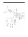
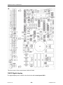
WIRING DIAGRAM
0740 800 144
- 7 -
© ESAB AB 2018
WIRING DIAGRAM
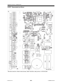
Component description
13AP1 Main circuit board, with the control electronics (see the description in
section "13AP1 Control board", page21)
13AP2 Circuit board with display, see the description in "13AP2 Digital
display", page34. Only for ESABFeed with M13 panel.
13C2 - 13C6 Capacitor, 0.1µF.
13CXX Capacitor, 4700µF. Must be fitted when the wire feed unit is used
under difficult applications (e.g. low mains voltage, long cables etc.).
13G1 Feed 484:
All serial numbers. Tachogenerator incorporated in motor 13M2.
Feed 304:
Up to and including serial no. 620-xxx-xxxx. Tachogenerator
incorporated in motor 13M1.
From serial no. 917-xxx-xxxx Pulsegenerator (encoder) incorporated
in motor 13M1.
See "13AP1:10 Tachometer input", page27.
13M1 Motor, rated voltage 42V. Feed 304.
13M2, 13M3 Motor, rated voltage 12V. Feed 484.
13RP1 Potentiometer, 10kOhm, for setting the wire feed speed.
13RP2 Potentiometer, 10kOhm, for setting the welding voltage. Only
ESABFeed with M13 panel.
13RP3 Potentiometer, 10kOhm, for setting the burn-back time.
13RP4 Potentiometer, 10kOhm, with incorporated switch, for setting the
crater fill time. Only ESABFeed with M13 panel.
13S1 Microswitch, monitoring the water connection. The pump in the water
cooling unit starts when the switched is closed.
13SA1 Switch, 2/4-stroke changeover. When the switch is closed, 4-stroke
control mode is selected.
13SA2 Switch, creep start function ON/OFF. When the switch is open, creep
start function is operative.
13XP1 Panel plug, for connection to the welding power source.
13XP2 Panel plug, for welding current connection from the power source.
13XS... Connectors with the designation 13XS... are socket connectors.
13XS13 23 pole panel socket for remote control.
13YV1 Gas valve

WIRING DIAGRAM
0740 800 144
- 8 -
© ESAB AB 2018
CAUTION!
STATIC ELECTRICITY can damage circuit boards and
electronic components.
• Observe precautions for handling electrostatic
sensitive devices.
• Use proper static-proof bags and boxes.

WIRING DIAGRAM
0740 800 144
- 9 -
© ESAB AB 2018
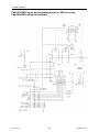
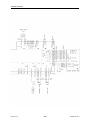
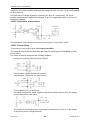
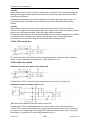
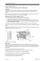
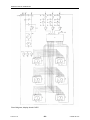
Feed 304 M12 up to and including serial no. 620-xxx-xxxx,
Feed484M12allserialnumbers

WIRING DIAGRAM
0740 800 144
- 10 -
© ESAB AB 2018

WIRING DIAGRAM
0740 800 144
- 11 -
© ESAB AB 2018
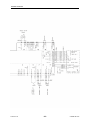
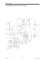
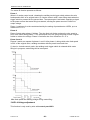
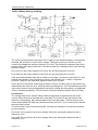
Feed 304 M12 serial no. 917-xxx-xxxx

WIRING DIAGRAM
0740 800 144
- 12 -
© ESAB AB 2018

WIRING DIAGRAM
0740 800 144
- 13 -
© ESAB AB 2018
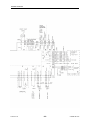
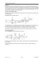
Feed 304 M12 from serial no. 623-xxx-xxxx

WIRING DIAGRAM
0740 800 144
- 14 -
© ESAB AB 2018

WIRING DIAGRAM
0740 800 144
- 15 -
© ESAB AB 2018
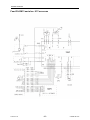
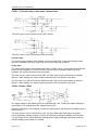
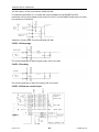
Feed 304 M13 up to and including serial no. 620-xxx-xxxx,
Feed484M13allserialnumbers

WIRING DIAGRAM
0740 800 144
- 16 -
© ESAB AB 2018

WIRING DIAGRAM
0740 800 144
- 17 -
© ESAB AB 2018
Feed 304 M13 serial no. 917-xxx-xxxx

WIRING DIAGRAM
0740 800 144
- 18 -
© ESAB AB 2018

WIRING DIAGRAM
0740 800 144
- 19 -
© ESAB AB 2018
Feed 304 M13 from serial no. 623-xxx-xxxx

WIRING DIAGRAM
0740 800 144
- 20 -
© ESAB AB 2018
Page is loading ...
Page is loading ...
Page is loading ...
Page is loading ...
Page is loading ...
Page is loading ...
Page is loading ...
Page is loading ...
Page is loading ...
Page is loading ...
Page is loading ...
Page is loading ...
Page is loading ...
Page is loading ...
Page is loading ...
Page is loading ...
Page is loading ...
Page is loading ...
Page is loading ...
Page is loading ...
-
 1
1
-
 2
2
-
 3
3
-
 4
4
-
 5
5
-
 6
6
-
 7
7
-
 8
8
-
 9
9
-
 10
10
-
 11
11
-
 12
12
-
 13
13
-
 14
14
-
 15
15
-
 16
16
-
 17
17
-
 18
18
-
 19
19
-
 20
20
-
 21
21
-
 22
22
-
 23
23
-
 24
24
-
 25
25
-
 26
26
-
 27
27
-
 28
28
-
 29
29
-
 30
30
-
 31
31
-
 32
32
-
 33
33
-
 34
34
-
 35
35
-
 36
36
-
 37
37
-
 38
38
-
 39
39
-
 40
40


ESAB Feed 304 M12 / M13 User manual
- Category
- Welding System
- Type
- User manual
- This manual is also suitable for
Ask a question and I''ll find the answer in the document
Finding information in a document is now easier with AI
Related papers
-
ESAB Secondary Power Board Assembly Installation guide
-
ESAB ESAB YardFeed 200 User manual
-
-
-
ESAB ESABFeed 48-4 M14 User manual
-
-
ESAB Warrior™ Feed 304 User manual
-
ESAB ESABMig 400t User manual
-
ESAB Powercut 700 User manual
-