190-01051-00 AHRS/Magnetometer Installation Considerations
Rev. C Page 1-3
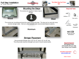
1.2 GRS 77 AHRS Installation Instructions and Considerations
Considering the placement information contained in Section 1.1, determine a suitable location for the GRS
77. The GRS 77 should be mounted to a surface known to have sufficient structural integrity to withstand
additional inertial forces imposed by the GRS 77 unit and any related components. For reference, the GRS
77 with Mounting Rack weighs 3.5 lbs and the addition of the GRS 77 Universal Mount increases the
weight to 4.55 lbs. Use of additional brackets or supplemental support structure will also increase weight.
This following sections provide an overview of possible GRS 77 mounting options for installation with
and without the GRS 77 Universal Mount.
There are four possible GRS 77 Universal Mounting options covered in this manual (refer to
Section 1.2.1
for instructions on installing the GRS 77 Universal Mount):
• Typical (
Section 1.2.2.1)
• Composite Aircraft (
Section 1.2.2.2)
• Tube and Fabric Aircraft (
Section 1.2.2.3)
• Using Existing Points from Previously-Installed Equipment (
Section 1.2.2.4)
There are three possible GRS 77 Mounting options without using the GRS 77 Universal Mount covered in
this manual:
• Mounting Bracket Attachment to Stringers or Longerons (
Section 1.2.3.1)
• Modifying Existing Floor Panel or Add mounting Surface to Attach GRS 77 Mounting Plate
(
Section 1.2.3.2)
• Plate, Angle Bracket Assembly Attachment to Existing Frame and Bulkhead Structure
(
Section 1.2.3.3)
In order to satisfy the structural requirements for the operation of the GRS 77 the following conditions
must be met for all installations:
1. If support racks, brackets or shelves need to be fabricated, they should be fabricated and attached
to the aircraft structure in accordance with the methods outlined in AC43.13-2A Chapter 2 and the
following requirements:
a) Material shall be 2024-T3 sheet aluminum
b) Material shall have some type of corrosion protection (primer, alodine, etc.)
c) Material shall be a minimum of 0.063” for single-sheet aluminum. Aluminum honeycomb
core panels are also acceptable, and have no minimum thickness requirements.
d) Use sheet metal techniques (bend radius, fillets, etc) appropriate to the material thickness
and type.
2. Any supporting structure must be rigidly connected to the aircraft primary structure through strong
structural members capable of supporting substantial loads. Avoid areas that are prone to severe
vibration (e.g., areas close to engine mounts and landing gear).
3. If a new mounting plate is fabricated for the GRS 77, the plate shall not span greater than 12” in
width or length without direct attachment to primary structure. If the mounting plate must span
more than 12”, stiffeners and/or flange reinforcements will be necessary to provide adequate
support.
4. Final installation shall be resistant to visual deflection during the validation of structures test per
Section 1.4.