4
When Installing the Unit
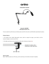
Applicable
to Central unit, Chairman unit, Delegate unit, Battery charger, and AC adapter
•Donotexposetheunittorainoranenvironmentwhereitmaybesplashedbywaterorotherliquids,asdoing
so may result in fire or electric shock.
1. SAFETY PRECAUTIONS
•Before installation or use, be sure to carefully read all the instructions in this section for correct and safe
operation.
•Be sure to follow all the precautionary instructions in this section, which contain important warnings and/or
cautions regarding safety.
•After reading, keep this manual handy for future reference.
Safety Symbol and Message Conventions
Safety symbols and messages described below are used in this manual to prevent bodily injury and property
damage which could result from mishandling. Before operating your product, read this manual first and
understand the safety symbols and messages so you are thoroughly aware of the potential safety hazards.
Applicable to Lithium-ion battery
•Shouldthefollowingirregularitybefoundduringuse,immediatelyswitchoffthepower,takethebatteriesout
of the unit, and keep them away from fire. Failure to do so may cause a fire or explosion.
· If you find battery leakage, discoloration, deformation or damage.
· If you detect smoke or a strange smell coming out from the batteries.
•Donot deform, modify, nor solder the batteries. Dosing so maydamage the battery's safety or protector
mechanism, causing the batteries to fire, leak, or explode.
•Nevershortthepositiveandnegativeterminalswithawireorothermetallicobjects.Also,avoidcarryingor
keeping the batteries with metallic objects such as necklaces or hair pins. Doing so may cause the batteries
to fire, explode, leak, or heat.
•Neverheatthebatteriesnorthrowthemintoafire.Doingsomaydamagethebattery'sgasreliefvalveor
safety mechanism, causing the batteries to fire or explode.
•Donotdipthebatteriesintowaternorwetthebatteryterminals. Thismaycorrodethebatteries,possibly
causing them to fire, explode, leak, or heat.
•Notecorrectpolarity(positiveandnegativeorientation)wheninsertingthebatteriesintoabatterycharger.
Doing otherwise may cause them to fire, explode, leak, or heat.
•Donotuse,keep,norleavethebatteriesnearfireorinlocationswherethetemperaturerisesabove60°C
suchasinasun-heatedcar.Dosingsomaydamagethebattery'ssafetyorprotectormechanism,causingthe
batteries to fire, explode, leak, or heat.
•BesuretousetheBC-900chargerwhenrechargingthebatteries.Usingotherbatterychargermaycause
them to fire, explode, leak, or heat.
•Usethebatteriesonlywiththeequipmentspecified.Failuretodosomaycausethebatteriestofire,explode,
leak, or heat.
•Donotdropthe batteries norgive thema shock. Doing so may damagethe battery's safety or protector
mechanism, causing the batteries to fire, explode, leak, or heat.
•Thereisafearofloosingone'seyesightifabatteryleakagegetsinone'seyes.Washitawaywithcleanwater
andconsultadoctorimmediately.Ifabatteryleakagestainsone'sskinorclothes,washitawaywithclean
water as there is a fear of impairing the skin.
Indicates an imminently hazardous situation, which, if not avoided,will
result in death or serious injury.
DANGER
Indicates a potentially hazardous situation which, if mishandled, could
result in death or serious personal injury.
WARNING