Page is loading ...

Operating & Maintenance Manual
for
JRZL-115 Rotary Lobe Frac Pumps
Dixon Sanitary
N25 W23040 Paul Road • Pewaukee, WI 53072
ph: 800.789.1718 • fx: 800.789.4046
dixonvalve.com
August 2018

2 Rotary Lobe Pumps - JRZL-115 Series800.789.1718
Table of Contents
Thank you for purchasing a Dixon Sanitary product!
This manual contains installation, operation, disassembly and assembly instructions, maintenance procedures, troubleshooting and a
complete parts list for all JRZL 115 frac pump.
READ THIS MANUAL carefully to learn how to service these pumps. Failure to do so could result in personal injury or equipment
damage.
Safety ................................................................................................................................................................................................... 3
Care of Stainless Steel ......................................................................................................................................................................... 4
Technical Specications ....................................................................................................................................................................... 5
Curves ............................................................................................................................................................................................... 6-7
Unpacking, Installation & Start Up ..................................................................................................................................................... 8-9
Tools Needed ..................................................................................................................................................................................... 10
Maintenance ....................................................................................................................................................................................... 10
Pump Housing Disassembly .................................................................................................................................................. 10-18
Pump Housing Inspection ........................................................................................................................................................... 19
Pump Housing Assembly ............................................................................................................................................................ 19
Rotor Clearance ..................................................................................................................................................................... 20-22
Rotor Timing ................................................................................................................................................................................ 23
Gear Box Disassembly ................................................................................................................................................................ 24
Frac Pump Disassembly ............................................................................................................................................................. 25
Gear Box Assembly..................................................................................................................................................................... 26
Scheduled Maintenance .............................................................................................................................................................. 26
Dimensions ......................................................................................................................................................................................... 27
Troubleshooting ............................................................................................................................................................................. 28-30
Repair Kits .......................................................................................................................................................................................... 30
BOM .............................................................................................................................................................................................. 31-35
Gear Box Assembly .................................................................................................................................................................. 31-32
Pump Assembly ............................................................................................................................................................................. 33
Rotor Set ........................................................................................................................................................................................ 33
Single Mechanical Seal .................................................................................................................................................................. 34
Hydraulic Motor Adapter Assembly ................................................................................................................................................ 35
Warranty ............................................................................................................................................................................................. 37

3Rotary Lobe Pumps - JRZL-115 Series 800.789.1718
Do’s & Don’ts
DO read and understand these instructions before installing or using the pump.
DO use Dixon spare parts when replacing a component of the pump.
DO NOT service the pump while it is running.
DO NOT place the pump in an application where the service ratings are exceeded.
DO NOT modify the pump. Modifying the pump creates unsafe conditions and voids all warranties.
Safety Precautions When Installing Pump
DO use an authorized electrician when connecting the pump.
DO observe the mechanical limits of the pump (refer to the pump performance sheet).
DO install a throttling valve in the discharge line.
DO NOT install a throttling valve in the suction line.
Safety Precautions When Operating Pump
DO allow only qualied personnel to operate this pump.
DO NOT start the pump until all personnel are clear.
DO NOT touch the pump or the lines when pumping hot uids or when performing Clean In Place (CIP) procedures.
DO NOT run the pump with BOTH the suction inlet and discharge outlet blocked. Running the pump with the inlet
blocked will cause serious damage to the pump.
DO NOT check pump rotation with liquid in the pump.
DO NOT run the pump with the front cover removed. The rotors and rotor case could be damaged or may cause severe
injury.
DO NOT operate the pump with the safety guard removed.
Safety Precautions When Servicing Pump
DO ensure the pump is cool to touch before performing service.
DO relieve all pressure and drain all uids from pump and connected piping before performing service.
DO ENSURE POWER TO THE UNIT HAS BEEN DISCONNECTED PRIOR TO PERFORMING ANY PUMP
MAINTENANCE OR CLEANING.
DO exercise caution and wear protective clothing when using lye or acid for cleaning.
Safety Information

4 Rotary Lobe Pumps - JRZL-115 Series800.789.1718
Care of Stainless Steel
The stainless steel components in Dixon Sanitary equipment are machined, welded and assembled by skilled craftsmen using
manufacturing methods that preserve the corrosion-resistant quality of the stainless steel.
Retention of corrosion-resistant qualities under processing conditions requires regular attention to the precautions listed below.
1. Regularly check all electrical devices connected to the equipment for stray currents caused by improper grounding, damaged
insulation or other defects. Corrosion: Pitting often occurs when stray currents come in contact with moist stainless steel.
2. Never leave rubber mats, ttings, wrenches, etc. in contact with stainless steel. Corrosion: Pitting or galvanic action. Objects
retard complete drying, preventing air from reforming the protective oxide lm. Galvanic corrosion occurs when two dissimilar
metals touch when wet.
3. Immediately rinse equipment after use with warm water until the rinse water is clear. Clean the equipment (manual or CIP)
as soon as possible after rinsing. Corrosion: discoloration, deposits, pitting. Product deposits often cause pitting beneath the
particles.
4. Use only recommended cleaning compounds. Purchase chemicals from reputable and responsible chemical manufacturers
familiar with stainless steel processing equipment, they continuously check the effects of their products on stainless steel.
5. Use cleaning chemicals exactly as specied by the manufacturer. Do not use excessive concentrations, temperatures or exposure
times. Corrosion: Pitting, discoloration, stress cracks. Permanent damage often occurs from excessive chemical concentrations,
temperatures or exposure times.
6. For manual cleaning, use only soft non-metallic brushes, sponges or pads. Brush with the grain on polished surfaces, avoid
scratching the surface. Corrosion: Pitting, scratches. Metal brushes or sponges will scratch the surface and promote corrosion
over a period of time. Metal particles allowed to remain on a stainless steel surface will cause pitting.
7. Use chemical bactericides exactly as prescribed by the chemical manufacturer in concurrence with local health authority. Use
the lowest permissible concentration, temperature and exposure time possible. Flush immediately after bacterial treatment. In no
case should the solution be in contact with stainless steel more then 20 minutes. Corrosion: Protective lm destroyed. Chlorine
and other halogen bactericides can destroy the protective lm. A few degrees increase in temperature greatly increases chemical
activity and accelerates corrosion.
8. Regularly inspect the joints in pipelines. Be sure all connections are tight tting without binding. Corrosion: Crevice corrosion.
Small crevices caused by improperly seated gaskets will promote crevice corrosion. Stainless steel under stress will develop
stress cracking especially in the presence of bactericides containing chlorine.
9. Regularly inspect equipment for surface corrosion (i.e. pitting deposits, stress cracks, etc.). If deposit or color corrosion is
detected, remove it immediately using mild scouring powder and detergents. Rinse thoroughly and allow to air dry. Review
production and cleaning procedures to determine the cause. Note: If corrosion is not removed, the protective lm cannot be
restored and corrosion will continue at an accelerated rate.

5Rotary Lobe Pumps - JRZL-115 Series 800.789.1718
JRZL 115-Series Technical Specications
Specications:
Model
Maximum Differential
Pressure (PSI)
1
Maximum Flow Rate
(GPM)
Temperature
Range
Viscosity
Range
Noise
Level
115 174 17
14°F to 356°F
(-10°C to 180°C)
Up to
1,000,000 cPs
60 ~ 80 dB
Materials:
• product wetted steel part: AISI 316L Stainless Steel (standard)
• product wetted elastomers: FKM (standard), EPDM, Buna (optional)
Shaft Seals:
• seal options: single mechanical
• stationary seal ring material: tungsten carbide
• rotating seal ring material: tungsten carbide
• O-ring material: FKM (standard), EPDM, Buna (optional)
Rotor Information: Not all rotors available in all models.
• single/bi-wing and bi-lobe/tri-lobe/heli-lobe are interchangeable
• optional rotors: multi-lobe, hardened
Optional Information:
• SAE-A or SAE-B hydraulic motor adapters
• bare shaft pump without hydraulic motor adapter
• adapter plates can be customized to meet existing bolt pattern

6 Rotary Lobe Pumps - JRZL-115 Series800.789.1718
JRZL 115 Curves

7Rotary Lobe Pumps - JRZL-115 Series 800.789.1718
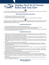
Rotary Lobe Pump JRZL115
NET POSITIVE SUCTION HEAD REQUIRED
PORT SIZE: 1.5 X 1.5
Dixon Sanitary
N25 W23040 Paul Road • Pewaukee, WI 53072
Customer Service: 800.789.1718
Fax: 800.789.4046
dixonvalve.com
0
5
10
15
20
25
0 100 200 300 400 500 600 700 800
NPSHR (PSIA)
SPEED (RPM)
JRZL115 NPSHR Curves

8 Rotary Lobe Pumps - JRZL-115 Series800.789.1718
Installation & Start Up
Pump Flow
Unpacking
Carefully unpack all parts of the pump and inspect for damage that may have occurred during shipment. Report any damages to the
carrier immediately.

9Rotary Lobe Pumps - JRZL-115 Series 800.789.1718
Installation & Start Up
Pump Alignment
• A exible coupling is used to compensate for end play and small differences in alignment. The pump and drive shaft should be
aligned as closely as possible.
• Check angular alignment using feeler or taper gauge.
• Adjust to get equal dimension at all points – at the same time, set space between coupling halves to the coupling manufacturer’s
recommended distance.

10 Rotary Lobe Pumps - JRZL-115 Series800.789.1718
Tools Needed
• Rotor tool
• Plastic dowel
• Open ended wrench set
• Rubber mallet
• Flat head screw driver
• Feeler gauges
• Hex keys
• O-ring pick
• Spanner wrench
• Rotor extraction tool (optional)
Additional tools needed when assembling or disassembling gear box
• Spanner wrench
• Arbor press or bearing puller
Maintenance
Pump Housing Disassembly
Prior to removal of pump, the shut-off valves in the suction and discharge lines must be closed. If there is any risk that product
may harden, crystallize or freeze in the pump it should be thoroughly drained and cleaned immediately after use. Same
attention applies if there is a seal ush option. Power needs to be locked out to prevent unintended start of the pump.
Note: Reference numbers are listed in the sectional view located on pages 32-33. Connections shown may be different.
1. Loosen and remove the four hex nuts (33) from the front cover.

11Rotary Lobe Pumps - JRZL-115 Series 800.789.1718
Maintenance
Pump Housing Disassembly (continued)
3. Remove the cover O-ring (34).
2. Remove the cover (32). If it is stuck, tap the cover with a soft hammer.

12 Rotary Lobe Pumps - JRZL-115 Series800.789.1718
Maintenance
Pump Housing Disassembly (continued)
4. Remove the rotor retaining bolts (35). To remove the rotor retaining bolts, place the dowel between the rotors. Turn the rst rotor
bolt counter-clockwise.
5. Remove the rotor bolts (35), spring washers (36) and O-ring (37).

13Rotary Lobe Pumps - JRZL-115 Series 800.789.1718
Maintenance
Pump Housing Disassembly (continued)
6. Remove the rotors (38) from the pump housing (31) by pulling straight.
6a. If the rotors (38) will not come out freely, remove the stud bolt hex nuts (46) and then tap on the back of the inlet and outlet ports
with a soft hammer. Once the rotors (38) are loose, then push the casing (31) back towards the gear box and remove the rotors.

14 Rotary Lobe Pumps - JRZL-115 Series800.789.1718
Maintenance
Pump Housing Disassembly (continued)
6a, continued

15Rotary Lobe Pumps - JRZL-115 Series 800.789.1718
Maintenance
Pump Housing Disassembly (continued)
7. Remove the seal ring (52) from the back of the rotor (38).
8. Remove the rotor O-rings (51).

16 Rotary Lobe Pumps - JRZL-115 Series800.789.1718
Maintenance
Pump Housing Disassembly (continued)
9. Remove the casing seal rings (52).
10. Remove the stud bolt hex nuts (46).

17Rotary Lobe Pumps - JRZL-115 Series 800.789.1718
Maintenance
Pump Housing Disassembly (continued)
11. Remove the rotor case (31).
12. Remove the rotor case O-ring (53). This can be done before you remove the casing or after.

18 Rotary Lobe Pumps - JRZL-115 Series800.789.1718
Maintenance
Pump Housing Disassembly (continued)
13. On the back of the rotor case, remove the four mechanical seal gland wrench bolts (42 & 43).
14. Remove the single seal body cases (54).

19Rotary Lobe Pumps - JRZL-115 Series 800.789.1718
Maintenance
Pump Housing Inspection
1. Inspect O-rings and seals for reuse. Worn O-rings and seals should be replaced.
2. Inspect seal faces for scoring or cracks. Replace any seal faces that are damaged.
3. Inspect rotors for any damage or abnormal wear.
4. Inspect rotors for wear on splines and that they t snuggly on the shafts.
5. Inspect shafts for wear on splines and make sure they are not loose in the gear case.
6. Inspect rotor galling sign among the rotor housing, front cover and rotors. Must be removed or replaced.
7. Inspect burr of the rotor bolt groove. Must be removed or replaced.
Pump Housing Assembly
Before installing the pump housing (31) to the gearbox make sure that the surface of the pump hosing and gear box are clean and
check the shim plate between pump housing and gear box. Install the pump housing (31) onto the gear box (1A) and secure the four
housing set nuts (46).
When installing the ceramic shaft sleeve onto the pump shaft, align sleeve with t pin.
Follow the disassembly instructions in reverse for all types of seals and rotor assembly.
Assemble a rotor onto shaft engaging the shallow groove with small spline in rotor and seal side
rst in to the shaft.
Place the plastic dowel between the rotors. Tighten the rst rotor bolt with a special tool to the recommended torque.
Model Rotor Nut Torque Specication
JRZL 115
116.3 in. lbs.
To tighten the second rotor place the plastic dowel on the opposite side of the rotor and tighten the second rotor bolt to the proper
torque.
Install the cover (32) and tighten the cap nuts (33).

20 Rotary Lobe Pumps - JRZL-115 Series800.789.1718
Maintenance
Rotor Clearance
Use feeler gauges to verify the back and radial clearances between the rotors and the housing. A depth gauge should be
used to verify the front clearance.
Rotor clearance must be precisely maintained to provide maximum pumping efciency, prevent contact between rotors, rotor housing
and front cover during operation. If pumping efciency is below expectations or if parts contact has occurred during operation (within
rated differential pressure) check rotor clearances and adjust if incorrect.
Standard Rotor Clearances (mm/in)
Model Back Face Front Face
Clearances for Rotor Timing
Radial Sides
Radial
Top & Bottom
Rotor to Rotor
JRZL 115 0.15/0.006 0.15/0.006 0.27/0.011 0.12/0.005
0.15/0.006
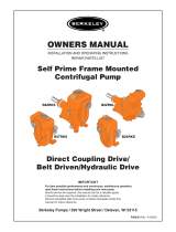
There are two areas of rotor clearances as illustrated following:
• Rotor tip clearance – not adjustable set by manufacturer
• Front and back face clearance – adjustable by shim
Figure 20
Shims
Rotor to Housing
Back
Face
Front
Face
Radial Top & Bottom
Rotor to Rotor
Radial Sides
/