Page is loading ...

KEY:
L = Left pieces
B = Back pieces
R = Right pieces
F = Front pieces
CT = Center–Top
G = Grille
T = Tray
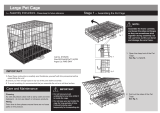
cage assembly instructions
Small Animal Cage
Model: # 425
cage: 32½"L × 21⅝"W × 33"H
interior, with grill: 31½"L × 20⅞"W × 17¾"H
interior, without grill: 31½"L × 20⅞"W × 24⅜"H
wire gauge: 8 & 12 wire spacing: 1"
getting started!
READ THESE NOTES FIRST:
• Count Hardware and Review All Parts: Usually, extra
screws are included. If the screw count is short, or if any parts
have been damaged during shipping, please contact Prevue
Customer Service.
• Tools: An allen wrench and flat wrench are included. You may
want to use your own hand tools but we
DO NOT recommend power
drills! Parts can be over-tightened and damaged/stripped. Prevue
is not responsible for this type of damage.
Review these instructions thoroughly before attempting to assemble
cage. If you still require assistance, please contact Prevue Customer
Service at 800.243.3624 or through links online at prevuepet.com
parts
5
Install the grille and tray: Rotate the windbell lock
out of the way, and slide the removable grill (G) (top
track) and plastic tray (T) (bottom track) into place.
6 Install the platform and ramp:
PLATFORM: Front, back and side edges of the
platform all have hooks that rest on horizontal
cage mesh wires. The interior edge has holes
for attachment of the ramp.
RAMPS: ‘U’ hooks along the top edge link into holes
along the platform’s interior edge. ‘L’ hooks along the
bottom edge rest on floor grille.
Hook ramp ‘U’ hooks into holes along platform’s cage
interior edge. With ramp attached to platform, position
platform on seventh vertical wire up from bottom,
making sure all platform hooks catch on horizontal
cage mesh wires for stability.
✩
Your cage is now fully assembled!
LEFT SIDE
FRONT
BACK
RIGHT SIDE
GRILLE
TRAY
L2
L3
L1
R2
R3
R1
T
G
F3
F2
F1
B3
B2
CT
B1
{12} hex head screws
{ 2 } locking and
{ 2 } rolling casters
{ 1 } allen wrench
{ 1 } flat wrench
{ 1 } metal platform
{ 1 } metal ramp
Made in China for Prevue Pet Products, Inc., Chicago IL USA www.prevuepet.com 800 243-3624 customerservice @prevuepet.com
T
G
425 — 05/13 — A4

1
a
Assemble the side panels: Starting with the left side
panel, slide the panel mesh (L3) into the left side frame
(L1), trapping the mesh between the pairs of “C” wires
on the frame legs. At the top of the mesh, wires extend
above the top of the panel. Align extended wires on
the mesh with holes on the underside of the frame.
2
a
Assemble the front and back panels: The front
lower (F1) and back lower (B1) rails have holes
on the top surface, and tray channels on the inside
surface. The tray channels end flush on the left
end, and extend beyond the rail on the right end
(see detail).
Orient the front lower (F1) rail with holes facing up
and tray channel facing in. Secure with hex screws
through the side frame legs on both ends.
Instructions are the same for back lower (B1) rail.
2
b
The front mesh (F2) panel has a door. The back
mesh (B2) panel is solid mesh. Both front and back
mesh panels have vertical wires extending above
and below the panel. The extended wires along the
bottom edge align with the holes on the top surface
of the front & back rails (F1 & B1).
Align the extended wires with the holes, and set
the front and back mesh panels into place.
1
b
Finish by attaching the frame bar (L2). The left side
frame (L1) has stop-tabs (to stop the grille and tray from
pushing all the way through), so the left side frame bar
does NOT include the windbell lock. The top surface of the
frame bar has holes which align with extended wires on
mesh. Align wires with holes, and secure the frame bar
with hex screws through the frame legs on both ends.
Instructions are the same for the right side (R1-3).
steps
2
c
The front upper (F3) and back upper (B3) rails
have extended curved tabs on the top surface, and
extended flat tabs on the inside ends (see detail).
Along the bottom surface are holes which align with
the extended vertical wires on the panel mesh.
Orient the front upper (F3) rail with the opening on
the curved tabs facing in, and the end flat tabs also
on the inside. Align the holes on the underside with
the extended wires on the mesh. Secure rail with hex
screws through the side frame legs on both ends.
Instructions are the same for back upper (B3) rail.
3 Insert the caster wheels: We suggest inserting the
two locking caster wheels on the front, where they
can be accessed easily when the cage is in use, but
all wheels will fit in all legs and locking casters can
be arranged to best suit your needs.
4 Install the roof panel: At the back of the roof (C1)
panel, the first horizontal wire is extended on both
ends. These extended wires will align with holes on
the left and right side frames (L1 & R1).
Loosen the hex screws for the back upper (B3) rail
to allow some slack.
Hook the first horizontal wire of the roof (C1) panel
under the curved tabs on the upper rail, and insert
the extended end wires into the holes on the side
frames. Retighten the back upper rail hex screws.
Check and tighten all other hex screws, to create a
solid, stable cage.
L3
R3
L2
R2
B3
L1
R1
F3
B2
F2
B1
F1
/


