Page is loading ...

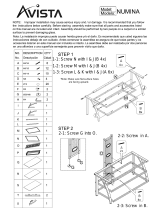
Introduction:
1. Hardware kit
Thank you for purchasing the KPM-312 LCD/LED dual monitor mount with gas spring
mechanism. This product is shipped with all proper installation hardware and components.
Upon opening the box, make sure that none of these parts are missing and/or damaged
before beginning installation.
LCD/LED dual monitor mount
with gas spring mechanism
KPM-312
Label
A
B
C
D
E
F
Item
Monitor mount assembly
C-clamp top plate
C-clamp bottom plate with knob
M6x10 plate retaining screw
M6x12 mounting screw
Grommet mount
Quantity
1
1
1
2
3
1
Image
C-clamp/Grommet base
configuration

IMPORTANT:
At least two qualified people should perform the assembly procedure. Personal injury and/or
property damage can result from dropping or mishandling the display.
Mounting surfaces must be sturdy and flat.
Do not install this product on a weak, uneven surface, prone to vibration or susceptible to
other movements. Reinforce the structure as necessary before installing the mount.
Supported monitor weight: Min 4.4lb / Max 14.3lb
The combined weight of all components shall not exceed the rated load capacity of the
mounting arm.
2. WARNING!
• Prior to installing this product, you must read all instructions thoroughly. Keep these installa-
tion instructions in an easily accessible location for future reference.
• Safety measures must be practiced at all times during the assembly of this product. Use
proper safety equipment and tools for the assembly procedure to prevent personal injury.
As arms are under tension and may suddenly spring upwards, keep them
to their highest position when removing the monitors. Failure to do so
may cause personal injury and equipment damage.
• Klip Xtreme does not warrant against damage caused by the use of any Klip Xtreme mounts
for purposes other than those for which it was designed or damage caused by unauthorized
attachments or modifications, and is not responsible for any damages, claims, demands, suits,
actions or causes of action of whatever kind resulting from, arising out of or in any manner
relating to any such use, attachments or modifications.
Max load 14.3lb
(each monitor)
6.5
kg
Label
G
H
I
J
K
M-A
M-B
M-C
Item
M8 wing nut
M8x105mm screw
Flat clamping plate
4mm allen wrench
5mm allen wrench
M4x12 screw
M5x12 screw
D5 metal flat washer
Quantity
1
1
1
1
1
4 (per arm)
4 (per arm)
4 (per arm)
Image
3. Product diagram
4. Desktop installation
Notes:
• The monitor mount allows two installation configurations.
It may be clamped to a desk or table, or mounted through a grommet hole. Instructions for
both will be provided in the following sections.
• First, decide where you prefer to place your monitors. Prior to attaching the mount to your
desk, make sure you have enough room to fit the entire assembly either behind or in the
cable hole area of your desk, depending on the mounting method you choose.
Option A - C-clamp mount
1. First, attach the C-clamp top plate tto the mount base using the supplied three mounting
screws and tight them firmly with the 4mm allen key.
115mm
75mm
100mm
+90˚
+45˚
min160mm - max410mm
10mm-83mm
98mm
55mm
160mm 50mm225mm-290mm
75mm
100mm
117mm
±360˚
±360˚
±360˚
±180˚

2. The clamp provides two positions depending on the thickness of your desk (from 10 to
83mm). The top screw hole is designed for thinner surfaces, while the bottom hole will fit
tabletops with thicker edges. Proceed to fix the bottom plate of the C-clamp with the
supplied screws based on the mounting depth needed, as illustrated below.
3. Slide the clamp base onto the edge of your desktop in your desired location. Tighten the
locking knob until the mount is securely attached to your desk surface.
Option B – Grommet mount
1. This option requires a hole through the mounting surface. After making sure the grommet
mount is facing up, insert the M8 screw through the square hole in the center of the
grommet mount.
2. Attach the grommet mount to the base with the three supplied screws. Use the allen key
to tighten the screws to the base.

Too short Correct Too long
3. Center the base over the top of the hole in the mounting location. From underneath the
surface, slide the flat clamping plate onto the M8 screw.
5. Installation of the monitor plate to the display
1. Carefully place your display face down on a soft, even surface, and identify the threaded
mounting points that are located on the back panel.
Note: If a stand is attached to a monitor, it must be removed now.
2. Determine the correct screw size by carefully inserting a straw or toothpick, and mark the
depth of the mounting point. Please note that not all the hardware included will be used.
CAUTION: Verify the adequate thread engagement of the screw/spacer combination on
your monitor. Too short will not hold the display and too long will damage it.
3. Using a phillips-head screwdriver, insert the first two screws and washers in the upper
mounting holes on the back of the monitor.
4. Use the wing nut to secure the assembly. Fasten the wing nut until the mount is firmly
attached to the desktop.
Note:
The M8 screw must be centered in the hole.
For security purposes and to avoid equipment damage, the base and the clamping plate must
make contact with the mounting surface on both sides of the hole.

4. Then simply slide the monitor onto the VESA plate by aligning the pear-shaped slots with
the screws attached to the monitor, until it is properly positioned in place.
5. Proceed to insert the other two screws and washers through the lower mounting holes of
the VESA plate. Tighten with the screwdriver to securely mount the monitor to the arm.
When doing so, be careful not to over-tighten the screws.
6. Repeat the same procedure to attach the second monitor to the other arm.
7. When both monitors are mounted, adjust the tension of each spring using the supplied allen
key. Lower the monitor down to access the screw. If the monitor is rising up, loosen the
screw by turning it to the left. If the monitor is falling down, tighten the screw by turning it
to the right. The monitor is properly counterbalanced when it can be moved vertically to
any position smoothly with just a touch.
8. Now unscrew the cable covers located under the arms. Route the monitor cables along the
channels, leaving enough slack to allow for proper movement, as shown below.
Monitor with flushed or recessed mounting holes

Notes
9. Replace the cable covers and secure them with the screws you just removed.
11. When the optimal viewing position is reached, fully tighten the screws of the joints in
both arms.
10. This dual side-by side monitor mount lets you adjust the viewing, tilt and swivel angles,
including the orientation of the screen (portrait or landscape).

/