Page is loading ...

2940 AIR ADJUST RESIDUE MANAGER
USING 2940-050A YETTER ELECTRIC COMPRESSOR
OPERATOR’S MANUAL
2565-773_REV_F ● 3/20
*Patented
YETTER MANUFACTURING CO.
FOUNDED 1930
Colchester, IL 62326-0358
Toll free: 800/447-5777
309/776-3222 (Fax)
Website: www.yetterco.com
E-mail: [email protected]
GERMINATE UNIFORMITY ™

2
TABLE OF CONTENTS
Bolt Torque…………………………………………………………..……………………2
Safety…………………………………………………………………..………………….4
2940 Components, Kits, Accessories, and Ordering Part Numbers…………..... 5-9
Introduction & System Requirements……………………….………………………..10
System Information...………………………………………………….……….…..11-14
Installation Instructions....................................................................................15-37
Installation Guide..........................................................15
Residue Manager/RM Coulter Combo....................16-19
Cab Controller...............................................................20
Compressor ..................................................................21
Control Box ...................................................................22
Compressor & Control Box Cable/Harnesses.......23-24
Dump Valve Assembly..................................................24
Airline Routing...............................................................25
Airline & Dump Valve Diagrams..............................26-37
Operation……………………………………………………………………………..38-44
Maintenance………………………………………………………………………….45-47
Parts Identification…………………………………………………………………...47-61
Troubleshooting……………………………………………………………………….....62
Notes.......................................................................................................................63
BOLT TORQUE
Mounting bolts and hardware
All hardware used on the 2940 Air Adjust is Grade 5 unless otherwise noted. Grade 5 cap screws are marked with three radial
lines on the head. If hardware must be replaced, be sure to replace it with hardware of equal size, strength and thread type.
Refer to the torque values chart when tightening hardware.
Important: Over tightening hardware can cause as much damage as when under tightening. Tightening hardware
beyond the recommended range can reduce its shock load capacity.
The chart below is a guide for proper torque. Use it unless a specified torque is called out elsewhere in the manual.
Torque is the force you apply to the wrench handle or the cheater bar, times the length of the handle or bar. Use a
torque wrench whenever possible.
The following table shows torque in ft. lbs. for coarse thread hardware.

3
FOREWORD
You’ve just joined an exclusive but rapidly
growing club.
For our part, we want to welcome you to the
group and thank you for buying a Yetter product.
We hope your new Yetter products will help you
achieve both goals-increase your productivity
and increase your efficiency so that you may
generate more profit.
This operator’s manual has been designed into
four major sections: Foreword, Safety
Precautions, Installation Instructions and Parts
Breakdown.
This SAFETY ALERT SYMBOL indicates
important safety messages in the manual.
When you see this symbol, be alert to the
possibility of PERSONAL INJURY and
carefully read the message that follows.
The word NOTE is used to convey information
that is out of context with the manual text. It
contains special information such as
specifications, techniques and reference
information of a supplementary nature.
The word IMPORTANT is used in the text when
immediate damage will occur to the machine
due to improper technique or operation.
Important will apply to the same information as
specified by note only of an immediate and
urgent nature.
It is the responsibility of the user to read the
operator’s manual and comply with the safe and
correct operating procedure and to lubricate and
maintain the product according to the
maintenance schedule in the operator’s manual.
The user is responsible for inspecting his
machine and for having parts repaired or
replaced when continued use of the product
would cause damage or excessive wear to the
other parts.
It is the user’s responsibility to deliver his
machine to the Yetter dealer who sold him the
product for service or replacement of defective
parts, which are covered by the warranty policy.
If you are unable to understand or follow the
instructions provided in this publication, consult
your local Yetter dealer or contact:
YETTER MANUFACTURING CO.
309/776-4111
800/447-5777
309/776-3222 (FAX)
Website: www.yetterco.com
E-mail: info@yetterco.co
WARRANTY
Yetter Manufacturing warrants all products manufactured and sold by it against defects in material. This
warranty being expressly limited to replacement at the factory of such parts or products as shall appear to
be defective after inspection. This warranty does not obligate the Company to bear cost of labor in
replacement of parts. It is the policy of the Company to make improvements without incurring obligations
to add them to any unit already sold. No warranty is made or authorized to be made, other than herein
set forth. This warranty is in effect for one year after purchase.
DEALER: ________________________________________
Yetter Manufacturing warrants its own products only and cannot be responsible for damages to
equipment on which mount

4
SAFETY
A brief description of signal words that may be used in this manual:
CAUTION: Used as a general reminder of good safety practices or to direct attention to unsafe practices.
WARNING: Denotes a specific potential hazard.
DANGER: Denotes the most serious specific potential hazard.
SAFETY PRECAUTIONS
You can make your farm a safer place to live and work if you observe the safety precautions given. Study these
precautions carefully and insist that those working with you and for you follow them.
Finally, remember this: an accident is usually caused by someone’s carelessness, neglect or oversight.
WARNING
Never clean, lubricate or adjust a machine that is in motion. Always lower or block the implement before performing
service.
If the machine must be serviced in the raised position, jack or block it up to prevent it from accidentally falling and injuring
someone.
Do not allow riders on the tractor or implement.
Use speeds and caution dictated by the terrain being traversed. Do not operate on any slope steep enough to cause
tipping or loss of control.
Be sure all personnel are clear of the immediate area before operating.
Read and understand the operator’s manual and require all other persons who will operate the equipment to do the same.
Be familiar with all tractor and implement controls and be prepared to stop engine and implements quickly in an
emergency.
CAUTION
Consult your implement and tractor operator’s manual for correct and safe operating practices.
Beware of towed implement width and allow safe clearance.
FAILURE TO HEED MAY RESULT IN PERSONAL INJURY OR DEATH.

5
Components, Kits, Accessories, & Ordering Numbers
Residue Manager Kits
2940-001A Pneumatic Residue Manager (RM) Assembly with choice of wheel kit (JD 1700 & 7200, White 9000)
2940-002A Pneumatic Narrow RM Assembly with choice of wheel kit (JD 1700 & 7200, White 9000, AME)
2940-003A Pneumatic RM Assembly with choice of wheel kit (CNH 800 – 1200)
2940-004A Pneumatic Narrow RM Assembly with choice of wheel kit (CNH 800 – 1200)
2940-005A Pneumatic RM Assembly with choice of wheel kit (JD 7000, White 6000 & 8000, Kinze 2000, 3000, & 4900)
2940-006A Pneumatic Narrow RM Assembly with choice of wheel kit (JD 7000, White 6000 & 8000, Kinze 2000, 3000, & 4900)
2940-007A Pneumatic RM/Coulter Combo with choice of wheel kit & coulter blade (JD 7000, White 6000 & 8000, Kinze)
2940-010A Pneumatic RM/Coulter Combo with choice of wheel kit & coulter blade (JD 1700 & 7200, White 9000)
2940-018 Coulter Less RM Less Blade for JD 7000, Agco 6000 & 8000, Kinze
2940-019 Coulter Less RM Less Blade for JD 1700, 7200, Agco 9000
Compressor Kit Control Kits
2940-050A Electric Pneumatic Compressor 2940-053 Pneumatic Control Box w/ Yetter Monitor
2940-053-LM Pneumatic Control Box Less Yetter Monitor
Air Lines and Wiring Kits
Compressor Mounting Kits
Part Numbers and Descriptions
2940-049 Air Adjust Mount Ext. Kit (For JD HD scrapers)
2940-100 Data Panel/Cab Controller--------------------------
2940-101A Electric Pneumatic Compressor ------------------
2940-103 Pneumatic Control Box -----------------------------
2940-112 VDM 12 Volt Controller-------------------------------
2940-113 RAM Cab Controller Mount Kit---------------------
2940-119 Electric Compressor Rebuild Kit
2940-126A Pneumatic Combo Sub-Assembly (2940-010)
2940-130A Pneumatic Combo Sub-Assembly(2940-007A)
2940-136 Dump Valve Kit----------------------------------------
2940-139 Pressure On Valve------------------------------------
2940-147 Package of 10 Tees----------------------------------
2940-065
6 & 8 Row Wiring/Tubing Kit
2940-067
12 & 16 Row Wiring/Tubing Kit
2940-072
Split Row/Interplant Kit
2940-087
ISOBUS Kit
2940-085
Bracket Two Point Hitch Kit 2940-090 8 X 12 Mount Kit
2940-086
Bracket Draft Tube Kit or Universal Kit 2940-091 8 X 16 Mount Kit

6
Components, Kits, Accessories, & Ordering Numbers
2940-148 Package of Zip Ties (100) ------------------------
2940-149 Manual Kit & Cab Controller Mount Bolt Bag
2940-150 Main Power Cable with 80A Breaker------------
2940-151 10 ft. Main Power Cable Extension -------------
2940-152 Hitch to Cab Controller CAN Cable-------------
2940-153 Cab Controller IGN/GRD Supply Harness----
2940-154 30 ft. Dump Valve Cable Black -----------------
2940-155 30 ft. Dump Valve Cable White-----------------
2940-156 15 ft. Dump Valve Cable Black
2940-157 15 ft. Dump Valve Cable White
2940-158 3 in. Y Harness Black-----------------------------
2940-159 3 in. Y Harness White--------------------------
2940-160 5 ft Dump Valve Cable White
2940-161 5 ft Dump Valve Cable Black
2940-162 Dump Valve Harness at Compressor---------
2940-163 20 ft Main Power Extension---------------------
2940-164 5 ft CAN Aux To Air Harness-------------------
2940-165 10 ft CAN Aux to Air Harness
2940-166 VDM Power Cable with 40 Amp Breaker---

7
Components, Kits, Accessories, & Ordering Numbers
2940-167 10 ft VDM Power Cable Extension-----------
2940-168 20 ft VDM Power Cable Extension
2940-169 10 ft Cab to Hitch Extension-------------------
2940-170 10 ft CAN Aux to Air Harness Extension ---
2940-171 30 ft CAN Aux to Air Harness Extension
2940-181 Hyd. Compressor Solenoid/Switch Harness
2940-182 20Ft Hyd. Compressor Control Harness-----
2940-189 10Ft Hyd. Compressor Control Harness
2940-190 Pneumatic RM Assembly (2940-001 - 004)
2940-192 Pneumatic RM Assembly (2940-005 - 006)
2940-209 CNH Adaptor Bracket (1260/1265 models)
2940-215 Air Adjust Wheel Mount W.A. -------------------
2940-216 Air Adjust Narrow Wheel Mount W.A. --------
2940-307 Draw Latch for compressor housing lid-------
2940-336 MAC Dump Valve----------------------------------
2940-337 3/8 Push to Connect (PTC) elbow 1/8 NPT-
2940-338 3/8 PTC Tee-----------------------------------------
2940-341 Air Tubing Cutter-----------------------------------
2940-342 Ball Valve--------------------------------------------
2940-345 Black 3/8 Air Tubing 100ft roll------------------
2940-346 Blue 3/8 Air Tubing 100ft roll-------------------

8
Components, Kits, Accessories, & Ordering Numbers
2940-352 3/8 PTC Plug(package of 5)-------------------
2940-357 Extreme Air Magnum Rebuild Kit-------------
2940-358 3/8 PTC Union, Straight-------------------------
2940-374 Tee-1)¼”NPT male, 2)¼”NPT female -------
2940-376 Updated Water Separator Drain Valve Kit--
2940-377 Compressor Pressure Switch-----------------
2940-379 PQE Inlet Elbow ¼ NPT to 3/8PTC----------
2940-380 3/8 PC X 1/8 BSPP O-Ring Straight Fitting-
2940-381 3/8PTC X 1/8BSPP O-ring Elbow Fitting----
2940-382 Shop Air Adapter----------------------------------
2940-383 3/8 PC WYE Fitting-------------------------------
2940-386 Shorter Air Bag------------------------------------
2940-388 Larger Air Bag-------------------------------------
2940-390 Extreme Air Magnum Compressor & Filter-
2940-391 100 AMP Compressor Relay, Continuous--
2940-395 Replacement Filter Element--------------------

9
Components, Kits, Accessories, & Ordering Numbers
2940-402 Full PQE Unit---------------------------------------
2940-404 Pressure Regulator (part of the 2940-415)
2940-408 3/8PTC Elbow Fitting 1/4NPT---------------- --
2940-415 Water Separator/Regulator Assembly--------
2940-416 175PSI Tank Safety Relief Valve---------------
2940-430 20 ft Can Aux to Air Harness Extension-----
2940-439 0 – 160psi Hydraulic Compressor Gauge---
2940-441 Pressure Transducer-----------------------------
2940-598 Plug Cap for Receptacle Protection---------
2940-599 Plug Cap for Receptacle Protection(metal)
2940-609 45 Degree Air Fitting 3/8PC X 1/8NPT ----
2940-635 3/8 PTC X 3/8 NPT 90 Degree Swivel -----
2966-293 CNH Adaptor Bracket---------------------------

10
INTRODUCTION
The Yetter Electric Air Compressor assembly builds 145psi of air pressure and dispenses that air to the row cleaners’ air bags as
the operator commands it from the tractor cab. Yetter electric compressors are durably constructed and designed for easy
integration to operate the Yetter 2940 Air Adjust System. The ability of the air adjustments allows the operator to adjust the row
cleaner precisely on the move without leaving the tractor cab resulting in more acres planted. The precise adjustments give the row
units and planter a more even, smoother ride leading to more accurate seed placement and seed depth resulting in a more uniform
emergence. IT IS NOT RECOMMENDED TO PLUMB ANY OTHER PNUEMATICALLY OPERATED SYSTEMS TO USE THE
2940 YETTER ELECTRIC COMPRESSOR AS ITS AIR SOURCE.
SYSTEM REQUIREMENTS
POWER SUPPLY
The compressor and the VDM (Valve Drive Module) each use 12V from the battery.
The 2940-100 Cab Controller uses a switched power source. The 2940-153 will need connected to a switched power source.
(Connector to the tractor not included)
A CIGARETTE LIGHTER OUTLET ISN’T A SWITCHED POWER SOURCE AND THEREFORE SHOULD NOT BE USED.
SWITCHED POWER SOURCE CONNECTOR PART #’S:
JOHN DEERE P/N: RE67013
CNH P/N: 187103A1
CAT P/N: AG233356
FUSE PROTECTION
To protect the compressor assembly & VDM from damage always ensure the integrity of the integrated 40 amp and 80 amp circuit
breaker at the tractor battery where cable connects to the battery in case of short or over-circuit. When connected correctly, the
tractor has a fuse to protect the cab controller located in the tractor’s fuse panel. NEVER MOUNT THE COMPRESSOR
ASSEMBLY MORE THAN 50 FEET FROM THE BATTERY USING THE PROVIDED MAIN POWER CABLES. THIS WILL
WEAKEN THE 80AMP BREAKER TO THE POINT OF FAILURE. IF MORE THAN 50 FEET IS NEEDED, BUILD POWER
CABLE(S) TO LENGTH USING 00 GAUGE CABLE!
AIR COMPRESSOR MAINTENANCE
To prolong life expectancy of the compressor, clean the filter on a regular basis by removing the element from the housing, tapping
it on a hard surface, exposed side down. This will empty the pleats of the filter of collected dust. If the dust has been wet or will not
clean out, call Yetter to order a new element, part number 2940-395. You may lightly blow out the interior of the upper housing
using an air tool. The housing and filter should be checked every two days of field operation, or more if conditions are very dusty.
See pages 45 for further maintenance.
CONNECTIONS
FAILURE TO LINE UP TABS WHEN PLUGGING MALE INTO FEMALE CONNECTORS CAN RESULT IN SHORT CIRCUIT.
ALSO CHECK TAB AND SLOT SIZES, PLUGGING CONNECTORS IN BACKWARDS WILL RESULT IN FAULTY SYSTEM!!

11
2940 AIR ADJUST SYSTEM INFORMATION
The 2940 Air Adjust Residue Manager control system consists of five primary components and kits. These parts include; Residue
Manager (RM) or Residue Manager Coulter Combo Kit, Cab Controller, the Yetter Electric Air Compressor Assembly, Compressor
Mounting Kit and the necessary Wires, Air Lines, and Fittings Kit.
Residue Manager RM/Coulter Combo
Each of these kits will include the required brackets, wheel assemblies, & mounting hardware for installation to the row unit.
Cab Controller
2940-100 RAM Mount
The Cab Controller will use the RAM mount provided for installation in
cab. Hold the POWER button to turn the cab controller on & press
ENTER to activate the system. Make adjustments quickly & accurately
during planting with the cab controller. Adjust up & down pressure to
create the ideal “ride” or floating position for residue managers. Lift &
down pressure settings can be adjusted independently. Down
pressure can be increased to fix row cleaner in the rigid position. Five
presets can be programmed within the controller for quick changes.
Residue Managers can be raised as needed with a push of the
Roman numeral I up button.
Serial Number
There are 2 serial numbers to identify production dates & software.
Cab Controller Serial Number VDM Serial Number

12
Air Compressor Assembly
2940 Air Adjust requires a stable air supply source that can provide a
minimum 145psi of clean, dry air. The ‘clean, dry air’ is a key component
of the air supply, moisture within the air supply can shorten the life-cycle
of the system. Another key component is having a leak free system to
reduce the duty cycle and compressor hours, extending the service life.
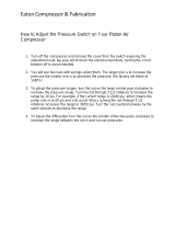
2940-101 External Lay Out
A – 2940-416 175psi Safety Relief Valve G – 2940-390 Electric Air Compressor
B – 2940-439 0 – 160psi Compressor Gauge H – 2940-395 Replacement Filter Element
C - 2940-377 Pressure Switch 125psi – 145psi I – 2940-391 100 Amp Compressor Relay
D – 2940-635 3/8”PTC X 3/8NPT 90° Fitting J – 2940-440 12G Tank Assembly
E – No Part # Main Power Connector K – No Part # Tank Drain Valve
F – 2940-336 Head Pressure Relief Valve

13
Control Box
The 2940-103 control box communicates with the 2940-100 cab controller via the VDM and dispenses air out of the Pneumatic Quick
Exhaust (PQE) as the operator commands it. The VDM is the valve drive module that is programmed to carry out each function of the
system. Serial # is located on the front of the VDM in the compressor assembly. See photo below.
2940-103 Control Box External Lay Out
2018 – Present Model
A. WHEEL TRACK DOWN PRESSURE PORT- Safely route black airline from the
WT port to the inlet port of the down pressure dump valve on the center/wheel
track rows of the planter. The down pressure on the center section residue
managers (RM) or RM/Coulter Combo can be adjusted separately than the
wing/outer sections down pressure to make up for tractor/planter tire
compaction. WT should be set 2-5 psi heavier than RD. If the WT port is not
used, install a plug (2940-352) to prevent air loss.
B. RESIDUE MANAGER DOWN PRESSURE PORT- Safely route black airline
from the RD port to the inlet port on the down pressure dump valves on the
wing/outer sections of the planter. This port dispenses down pressure to the RM
or RM/Coulter Combos on the wing/side of the planter.
C. RESIDUE MANAGER UP PRESSURE PORT- Safely route blue airline from
the RU port to the inlet port of the up pressure dump valves on each section of
the planter. This port dispenses up pressure to each RM or RM/Coulter Combo
on the planter.
D. 12 PIN DEUTSCH CONNECTOR (BLACK)- Depending on application, route
2940-164 or 2940-165 CAN AUX cable from rear of the tractor to this female
connector. If the control box is mounted at the rear of the planter, 2940-170,
2940-171, or 2940-430 CAN AUX extensions will route to this female connector.
E. 12 PIN DEUTSCH CONNECTOR (GRAY)- Connect the 2940-162 dump valve
cable and route to the dump valves. The 2 pin cable labeled RM UP DUMP
(yellow/black wires) routes to all up pressure dump valves. The 2 pin cable
labeled RM DOWN DUMP (orange/black wires) routes to all down pressure
dump valves. The 2 pin cables labeled Aux 3 and Aux 4 are not used.
F. MAIN AIR SUPPLY INLET- Plumb the 2940-367 250psi rated 3/8” airline from
the hydraulic compressor to the inlet (water trap side) of the water
separator/regulator assembly. Plumb 2940-345 3/8” black airline from outlet
(regulator side) of the water separator/regulator assembly to this port.
G. ACCESSORY AIR OUTPUT- Remove brass cap or plug to install fitting for
miscellaneous uses. (ex: air tools) DO NOT REMOVE WHEN SYSTEM IS
PRESSURIZED!
H. DUMP INLET- Install the ¼” airline from the bottom of the water separator into
this port.
I. DUMP EXHAUST- Install ¼” airline in this port and route toward the ground.
(this will drain condensation from the water separator)
J. COMPRESSOR COMMUNICATION CONNECTOR- Sends power to the
pressure switch & solenoid (see page 24)

14
2940-103 Control Box Internal Lay Out
2018 – Present Model
Harness, Airlines, and Fittings Kit
12V-DC cables will be used to power the Compressor, VDM, Cab Controller, and Dump Valves. Flexible tubing will be
used to move air from the external ports of the PQE to each air bag. Each kit will include pneumatic lines for both circuits,
down and lift, as well as the fittings to make connections and cable ties to securely fasten the lines to the planter. Note: All
2940 Air Adjust kit include a tubing cutter within the kit.
The 2940-341 tubing cutter should be used for every cut to ensure a clean, square cut.
A – 2940-112 VDM
1. J1 Compressor Communication
2. J2 Dump Valve Communication
3. J3 PQE Communication
4. J4 Plugged(used only with 2940-054 kits)
5. J5 VDM Power and Ground
6. J6 Cab Controller Communication
B – 2940-402 PQE
C – 2940-441 Pressure Transducer
D – 2940-379 PQE Inlet Elbow
E – 2940-376 Water Separator Dump Valve

15
2940 Air Adjust Installation Guide Outline
STEP 1: RESIDUE MANAGER (RM) OR RM/COULTER COMBO INSTALLATION
Residue Manager Only: Install the RM Assembly using mounting hardware. When installing wheel mount assembly on the adjustment tube of
the RM Assembly, place the top hole of the wheel mount to the 4
th
or 5
th
hole from the top of the adjustment tube for conventional tillage or mellow
soils, 5
th
or 6
th
hole from the top for no/minimum till conditions. Install wheels on wheel mounts using hardware from the 2966-119 bolt bag. Install
the RM wheels so that the left wheel leads, right wheel trails on the left side of the planter & the right wheel leads, left wheel trails on the right side.
RM/ Coulter Combo: Install the RM/Coulter Combo assembly using hardware from the 2940-128 bolt bag. Mount the coulter blade on the coulter
arm hub & mount the RM wheels using the 5/8 Whiz Lock Nuts. RM wheels on combo units will install in the rear holes on both sides on all rows. It
is recommended to set the coulter blade equal to or above seed depth. Refer to the diagrams on pages 16 - 19
STEP 2: INSTALLING 2940-100 CAB CONTROLLER
Mount the 2940-100 Cab Controller & 2940-113 RAM Mount in the tractor cab. Position the Cab Controller within reach during operation without
compromising safety/visibility from the cab. Connect the 2940-152 harness to the female 6 pin connector on the back of the cab controller & route
the black CAN connector towards the hitch of the tractor. Connect the 2940-153 2 pin connector to the female 2 pin connector on the back cab
controller. Splice the red & black wires to the appropriate connector to fit the tractor’s switched power source. Refer to the diagram on page 20
STEP 3: INSTALLING COMPRESSOR ASSEMBLY & POWER CABLES
COMPRESSOR: Begin by locating a suitable mounting location for the compressor assembly. Placement of the compressor assembly will vary on
the make and model of the planter. Use mounts supplied or depending on application, different mounts may need to be built. NOTE: Be sure to
check clearance of compressor assembly in all locations, especially noting tractor tires during turns, folding/unfolding the planter for transport
mode, markers, and 2-point top link. The compressor must be mounted using 50 feet or less of main power cable extensions from the operating
tractor’s battery. If over 50 feet, heavier gauge power cables (00) must be built or purchased in the correct length.
POWER CABLE: Install the 2940-150 main power cable with 80amp breaker on the battery terminals (red is positive+, black is negative -). Next,
connect the appropriate length of main power extensions (2940-151 or 2940-163) off of the 2940-150, route the main power extensions to large
Anderson power connector coming out of the 2940-101A compressor assembly housing, & install. Install the 2940-181 Y harness on the
compressor. Refer to the diagram on pages 21 & 23
STEP 4: CONTROL BOX AND HARNESS INSTALLATION
CONTROL BOX: Mount the control box in a safe location with mounts/hardware supplied. Install the 2940-415 water separator/regulator assembly
near the control box. Measure & cut the 2940-367 250psi rated 3/8” airline, install airline from outlet elbow on compressor into the 2940-415 inlet
(water trap side). The regulator is preset to only allow 100psi of clean, dry air beyond it. Install 2940-345 3/8” airline from the 2940-415 outlet
(regulator side) to control box inlet. Install ¼” airline from the elbow on the bottom of the 2940-415 to the ¼”PTC fitting closest to the door hinge on
the side of the control box. Route ¼” airline from remaining ¼”PTC fitting on the 2940-103 toward the ground, as airline will dispense moisture.
HARNESS: Install the 2940-166 VDM power cable with 40amp breaker on the battery terminals (red is positive+, black is negative -). Install the
appropriate length VDM power extension (2940-167 or 2940-168) off of the 2940-166, route to the hitch of the tractor to install into the matching
connector on the CAN AUX to Air Harness. Lastly, install the CAN AUX to Air Harness, 2940-164 (5ft) or 2940-165 (10ft). The smaller Anderson
power connector will connect to the VDM power extension, the black CAN connector connects to the other black CAN connector that routes to the
cab controller, & the black male 12 pin Deutsch connector connects to the black female end on the side of the control box housing. 2940-170
(10ft), 2940-171 (30ft), or 2940-430 (20ft) CAN AUX to Air Extensions may be necessary if the control box is mounted further back on the planter
than the hitch. Install the compressor communication harness, 2940-182 or 2940-189 into the 4 pin connector on the control box and route to the
compressor and install into the 2940-181 Y harness. Refer to the diagram on page 22 - 24
STEP 5: DUMP VALVE & DUMP VALVE HARNESS INSTALLATION
Install the dump valves (DV) to the planter as shown in the diagram that matches your planter. 16 row planters and less will have 1 up pressure &
1 down pressure DV on the middle of each wing/side & 1 up pressure & 1 down pressure DV on the wheel track (WT) or center rows. 24 row
planters & larger will have 3 DVs per wing/side; 2 down pressure & 1 up pressure, & 2 DVs on the WT rows, 1 up pressure & 1 down pressure.
Install the gray male 12 pin Deutsch connector of the 2940-162 into the gray female 12 pin Deutsch on the bottom side of the compressor
assembly housing. The 2940-162 will have 4) 2 pin pig tails. The connector labeled RM Up Dump (yellow/black wires) will connect to all up
pressure DVs using 2940-155 (30ft), 2940-157 (15ft), & 2940-160 (5ft) white DV harnesses. Use 2940-159 white Y harnesses to connect all white
DV cables together. The connector labeled RM Down Dump (orange/black wires) will connect to all down pressure DVs using 2940-154 (30ft),
2940-156 (15ft), 2940-161 (5ft) black dump valve harnesses. Use 2940-158 black Y harnesses to connect all black DV cables together.
CONNECTORS LABELED AUX 3 & AUX 4 WILL NOT BE USED! Refer to pages 24 - 36
STEP 6: PLUMBING AIRLINES
A group of airlines that route to the residue manager air bags are referred to as trunk airlines. The airline routing from the RU, RD, & WT to the
inlet of the DV for the matching circuit is referred to as a supply airline. Start by routing the trunk airlines: route black (down pressure) & blue (up
pressure) airline on each wing/side of the planter. If installing on a split row planter, keep the airline on the front rank residue managers on each
wing plumbed separate from the back rank. When plumbing in the WT (wheel track) rows, use the center 4 or 6 rows that plant over the tractor &
planter wheel tracks. If equipping on a narrow transport planter with 4 center rows & 6 rows are desired on the WT circuit, tie in the 1 row on each
wing/side of the planter closest to the first & last center row. Use supplied tees to make enough open ports in each circuit to install supply airline to
the inlet port of each DV of the matching circuit. Also use tees to connect the outlet port of the DVs to the matching circuits of the trunk airlines. On
split row planters, a ball valve will be used to shut air off to bean rows when planting corn. Refer to the diagrams on pages 25 - 37
STEP 7: PERFORM A PRE-OPERATIOIN TEST OF THE SYSTEM
Now that the system is installed, perform a pre-operation test. Start by folding/unfolding & lowering/raising the planter to check for enough slack in
airline & in harnesses at hinge points. Check all electrical connections, cables, & airline making sure nothing was damaged. Next, turn on the cab
controller by holding the power button. After the cab controller is on, turn all pressures (RU, RD, and WT) to 0psi & press ENTER to activate the
system. The compressor will turn on, build to 95psi & turn off. Check the interior of the compressor housing (PQE, Pressure on Valve, & airline
within the housing) for leaks. Apply 30psi to the RU port & watch your row cleaners as they should all rise to maximum up travel. Check for leaks
on all up pressure circuits & fittings. When that leak check is finished, turn RU to 0psi & turn RD & WT to 30. Check all down pressure airline &
fittings in these circuits for leaks & repair as needed. Refer to page 42 - 44

16
Residue Manager(RM) Installation
ENGAGE THE CYLINDER STOPS ON THE PLANTER LIFT WHEELS TO “LOCK” THE PLANTER IN THE UP POSITION
Installation overview:
Prior to installation of each RM mounting bracket assembly, check the freedom of motion of the parallel linkage or pivot arm.
The installation process should be done with the planter raised, half folded for transport, & the row units fully extended down.
Install the 2940 RM or RM/Coulter Combo mounting bracket assembly centered & level side to side on each planter row unit.
If planter manufacturer is John Deere & equipped with HD scrapers on the True V opener blades, a 2940-049 kit will need installed
to space the RM or RM/Coulter Combo mounting bracket assembly out to avoid interference. (See page 48)
For John Deere, Kinze, & White Models Installing RM Only
Step 1: Place 1) Pneumatic RM Assembly, 1) Mounting Hardware Bolt Bag (2940-142), 1) Wheel Mount Weld Assembly (2940-215 or
2940-216), 1) RH Wheel Assembly (2966-140), 1) LH Wheel Assembly (2966-141), & 1) Wheel Mount Bolt Bag (2966-119) at each
planter row unit. Install the Pneumatic RM assembly using 3) ½” X 1-1/2” GR5 bolts, 6) ½” flat washers, & 3) ½” lock nuts. Use the
diagram below for hole alignment, as well as direction of the mounting bolts. Tighten the hardware.
Tools needed are ¾ socket, ¾ wrench, impact, & 10” extension.
NOTE: AGCO 9000 units will use ½” x 2” mounting bolts!

17
For Case Models Installing RM Only
Step 1: 800 – 1200 SERIES: Place 1) Pneumatic RM Assembly (2940-190), 1) CNH Adaptor Bracket (2940-209), 1) CNH
Mounting Bolt Bag (2940-145), 1) Wheel Mount (2940-215/2940-216), 1) Cyclo Stop Casting Bolt Bag (2965-135), 1) RH Wheel
Assembly (2966-140), 1) LH Wheel Assembly (2966-141), & 1) Wheel Mount Bolt Bag (2966-119), & 2) Bearing Shields (2967-
392) at each row unit. Mount the 2940-190 to the 2940-209 using 3) ½” X 1-1/2” GR5 bolts (note the bolt direction), 3) ½” flat
washers, & 3) ½” lock nuts. Mount this assembly to the row unit attachment casting using 2) ½” X 3-1/2” bolts & 2) ½” lock nuts.
Install the 2) Cyclo Stop casting pieces to each upper parallel arm using either A) 3/8 X 1-¼ bolts, 3/8 washer (not shown), & 3/8
lock nuts or B) ½” X 1-1/4” bolts & ½” lock nuts. Note the direction of the mounting bolt.
2100 SERIES: Place 1) Pneumatic RM Assembly (2940-190), 1) Mounting Hardware Bolt Bag (2940-142), 1) Wheel Mount W.A.
(2940-215/2940-216), 1) RH Wheel Assembly (2966-140), 1) LH Wheel Assembly (2966-141), & 1) Wheel Mount Bolt Bag
(2966-119), & 2) Bearing Shields (2967-392) at each planter row unit. Use the same bolt direction as below. The top to
mounting bolts will be the same as diagram below. Use the bottom hole that is aligned with the OEM CNH faceplate adaptor.
Tools needed are ¾ socket, 9/16 socket, ¾ wrench, 9/16 wrench, impact wrench, & 10” extension.
Step 2: Install 1) 2940-380 3/8” PTC X 1/8” BSPP male fitting to each air bag using an 11/16 wrench. Do not over tighten.
Hold the air bag
while tightening
each air fitting.

18
Residue Manager Installation Con’t
Step 3: Install the Wheel Mount (2940-215 or 2940-216) on the adjustment tube of the mounting bracket assembly.
Recommended mounting location is 5
th
hole down from the top of the adjustment tube mounts to the top hole of the wheel
mount. Adjustments may need to be made depending on tillage practice, soil conditions, and/or residue thickness.
Tools needed are a 9/16 socket, 9/16 wrench, impact, and a 10” extension.
Step 4: Mount the RM wheels on the wheel mount using 2) 5/8” lock washers & 2) 5/8 hex nut. Mount the wheels so the left
side of the planter has the left wheel leading, right wheel trailing. Mount the wheels so that right side of the planter has the
right wheel leading, left wheel trailing. Right & left is determined by standing behind the planter looking at the tractor or sitting
in the tractor facing forward. Diagram below is proper installation for the right side of the planter. Tighten using a 15/16
wrench. (Ratcheting wrench if available) Note: Properly install row cleaner wheels so that wheel teeth curve back
when entering field debris.
It is highly recommended to wear gloves & use caution when tightening wheels!

19
RM/Coulter Combo Installation
Step 1: Place 1) RM/ Coulter Combo assembly, 1) Coulter Blade, 1) Mounting Bolt Bag (2940-128), 1) RH wheel assembly (2966-
116), & 1) LH wheel assembly (2966-117) at each row unit. Mount the RM/Coulter Combo assembly to the row unit face plate using
3) ½” X 1 ½” bolts and 3) ½” lock nuts. See the diagrams below for bolt alignment and bolt direction. Tighten hardware.
Tools needed are ¾ socket, ¾ wrench, impact, & 10” extension.
Step 2: Install coulter blade using 4) ½”X1 ¼” bolts & 4) ½” lock nuts using a ¾ socket, ¾ wrench, impact, & 10” extension.
NOTE: Adjust coulter blade depth equal to or above the planter opener blades. Adjust the blade depth as required for blade wear.
Planter double disc blades that are worn to 14 ¼” or smaller in diameter should be replaced. Example: 14 ¼” blades will have a 3/8”
shallower planting depth than 15” blades at the same gauge wheel adjustment setting.
STEP 3: Install each of the RM wheels in the rear D-bolt holes using a 5/8 serrated flange nuts & tighten using a 15/16 wrench.
It is highly recommended to wear gloves & use caution when tightening wheels!

20
Yetter Cab Controller Installation
(Skip this page if using ISOBUS monitor)
Step 1: Begin installing the 2940 Air Adjust cab controller once an adequate mounting location has been found. Fix the base
component of the 2940-113 Mounting Bracket in place. Use items labeled B if mounting to a slotted, flat mounting system using a
ratchet, 11mm socket, & 11mm wrench to tighten the hardware. Use items C if using a tubular mounting system. 2 different sized U-
bolts are provided for tubular mounting systems. Use a ratchet & 5mm socket to tighten the hardware.
Step 2: Connect the mount bracket to the rear of the controller using 4) M5 Hex Nut and 4) M5 split washers (labeled A) using a
ratchet & 8mm socket to tighten the hardware. Set the cab controller in place and tighten the clamp by turning the handle clockwise.
Step 3: Attach the male 2 pin connector of the 2940-153 to the female 2 pin connector on the 2940-100 Cab Controller. Install the
connector not provided for your tractor at the bare end of the 2940-153 and connect to tractors switched power source. The
cigarette outlet is NOT a switched port on all models of tractors, and therefore should not be used.
Switched Power Source Connector part #’s:
JOHN DEERE PART #: RE67013
CNH PART #: 187103A1
CAT P/N: AG233356
Step 4: Route & install the 2940-152 hitch to switch
panel wire harness from the rear 6 pin connector of the
2940-100 Cab Controller to the hitch-point at the rear
of the tractor. The black CAN connector of the 2940-152
will connect to the 2940-164 or 2940-165 CAN AUX
to Air Harness. (See page 23 for further details) If an
extension is needed between the 2940-100 Cab Controller
and this harness, a 2940-169 10ft cab to hitch extension is
available to order.
/