Page is loading ...

KSA
Centrifugal fan in sound insulated casing
USER’S MANUAL

2
KSA
www.ventilation-system.com
Safety requirements ..................................................................................................................................................................... 3
Purpose ................................................................................................................................................................................................ 5
Delivery set ........................................................................................................................................................................................ 5
Designation key .............................................................................................................................................................................. 5
Technical data .................................................................................................................................................................................. 6
Design and functioning ............................................................................................................................................................ 7
Mounting and set-up .................................................................................................................................................................. 8
Connection to power mains .................................................................................................................................................. 9
Technical maintenance .............................................................................................................................................................. 10
Troubleshooting ............................................................................................................................................................................. 11
Storage and transportation regulations .......................................................................................................................... 11
Manufacturer’s warranty ........................................................................................................................................................... 12
Certificate of acceptance .......................................................................................................................................................... 13
Seller information .......................................................................................................................................................................... 13
Installation certificate .................................................................................................................................................................. 13
Warranty card ................................................................................................................................................................................... 13
This user’s manual is a main operating document intended for technical, maintenance, and operating staff.
The manual contains information about purpose, technical details, operating principle, design, and installation of the KSA unit and all its
modifications.
Technical and maintenance staff must have theoretical and practical training in the field of ventilation systems and should be able to
work in accordance with workplace safety rules as well as construction norms and standards applicable in the territory of the country.
CONTENTS
SAFETY REQUIREMENTS
All user’s manual requirements as well as the provisions of all the applicable local and national
construction, electrical, and technical norms and standards must be observed when installing
and operating the unit.
Disconnect the unit from the power supply prior to any connection, servicing, maintenance, and
repair operations.
Only qualied electricians with a work permit for electrical units up to 1000 V are
allowed for installation and maintenance. The present user’s manual should be carefully
read before beginning works.
• Check the unit for any visible damage of the impeller, the casing, and the grille before starting
installation. The casing internals must be free of any foreign objects that can damage the
impeller blades.
• While mounting the unit, avoid compression of the casing! Deformation of the casing may
result in motor jam and excessive noise.
• Misuse of the unit and any unauthorised modifications are not allowed.
• Do not expose the device to adverse atmospheric agents (rain, sun, etc.).
• Transported air must not contain any dust or other solid impurities, sticky substances, or
fibrous materials.

3
www.ventilation-system.com
• Do not use the unit in a hazardous or explosive environment containing spirits, gasoline,
insecticides, etc.
• Do not close or block the intake or extract vents in order to ensure the efficient air flow.
• Do not sit on the unit and do not put objects on it.
• The information in this user’s manual was correct at the time of the document’s preparation.
• The Company reserves the right to modify the technical characteristics, design, or
configuration of its products at any time in order to incorporate the latest technological
developments.
WARNING! Similar to the use of any other household electrical appliances when
operating this fan, the following basic rules must be followed:
• Never touch the unit with wet or damp hands.
• Never touch the unit when barefoot.
This appliance is not intended for use by persons (including children) with reduced physical,
sensory or mental capabilities, or lack of experience and knowledge, unless they have been
given supervision or instruction concerning use of the appliance by a person responsible for
their safety.
Children should be supervised to ensure that they do not play with the appliance.
The connection to the supply mains must be made through a means of disconnection,
which is incorporated in the fixed wiring in accordance with the wiring rules, and has a
contact separation in all poles that allows for full disconnection under overvoltage category III
conditions.
If the supply cord is damaged, it must be replaced by the manufacturer, its service agent, or
similarly qualified persons in order to avoid a safety hazard.
The appliance is reset by disconnection of the supply mains.

4
KSA
www.ventilation-system.com
THE PRODUCT MUST BE DISPOSED SEPARATELY AT THE END OF ITS SERVICE LIFE.
DO NOT DISPOSE THE UNIT AS UNSORTED DOMESTIC WASTE.
Ensure that the appliance is switched off from the supply mains before removing the guard.
WARNING: If unusual oscillating movements is observed, immediately stop using the appliance
and contact the manufacturer, its service agent or suitably qualified persons.
The replacement of parts of the safety suspension system device shall be performed by the
manufacturer, its service agent or suitably qualified persons.
Fixing means for attachment to the ceiling such as hooks or other devices shall be fixed with a
sufficient strength to withstand 4 times the weight of the appliance.
The mounting of the suspension system shall be performed by the manufacturer, its service
agent or suitably qualified persons.
The appliance is to be installed so that the blades are more than 2.3m above the floor.
Precautions must be taken to avoid the back-flow of gases into the room from the open flue of
gas or other fuel-burning appliances.

5
www.ventilation-system.com
Designation example: KSA 160 4 E U
Fan name
KSA – centrifugal fan in sound insulated casing
Outlet spigot diameter [mm]
Pole number
Power mains specications
E – single phase
D – three-phase
Options
R1 – power cord with a mains plug
P – integrated speed controller
U – speed controller with an electronic thermostat and a temperature sensor integrated inside
an air duct. Temperature-based operation logic
Un – speed controller with an electronic thermostat and an external temperature sensor fixed
on a 4-meter cable. Temperature-based operation logic
U1 – speed controller with an electronic thermostat and a temperature sensor integrated inside
an air duct. Timer-based operation logic
U1n – speed controller with an electronic thermostat and an external temperature sensor fixed
on a 4-meter cable. Timer-based operation logic
NAME NUMBER
Fan 1 pc.
User’s manual 1 pc.
Packing box 1 pc.
The Centrifugal fan in sound insulated casing is designed for supply and exhaust ventilation of domestic, public and industrial premises
with high requirements to the noise level and with limited space for mounting.
The unit is rated for continuous operation.
The unit is a component part and is not designed for stand-alone operation.
Transported air must not contain any flammable or explosive mixtures, evaporation of chemicals, sticky substances, fibrous materials,
coarse dust, soot and oil particles or environments favourable for the formation of hazardous substances (toxic substances, dust,
pathogenic germs).
PURPOSE
DELIVERY SET
DESIGNATION KEY

6
KSA
www.ventilation-system.com
The fan is designed for operation in an enclosed area at ambient temperatures from -1 °C up to +45 °C.
The fan is rated as a class I electric appliance.
• Ingress protection rating against access to hazardous parts and water ingress is IPX2.
The fan design is regularly improved, so some models may slightly differ from those ones described herein.
OVERALL AND CONNECTING DIMENSIONS OF THE FANS
Model
Dimensions [mm]
Weight
[kg]
Ø D 1 L L1
KSA 100-2E 99 294 260 309 136 184 4.2
KSA 125-2E 124 310 260 309 154 206 4.6
KSA 150-2E 149 350 295 344 183 231 6.3
KSA 160-2E 159 350 295 343 183 231 6.3
KSA 200-4E 199 436 361 409 233 282 8.3
MAIN TECHNICAL PARAMETERS OF THE FANS
KSA 100-2E KSA 125-2E KSA 150-2E KSA 160-2E KSA 200-4E
Voltage [V/Hz] 1~230/50
Power [W] 130 155 335 335 115
Current [A] 0.60 0.70 1.50 1.50 0.50
Maximum air capacity [m
3
/h] 425 505 750 750 640
Max. air capacity [l/s] 118 140 208 208 178
RPM 2870 2870 2870 2870 1350
Sound pressure level at 3 m distance [dBA] 36.1 38.3 39.4 37.9 29.1
Transported air temperature [°С] -25...+40
Ingress protection rating IP X2
Motor protection rating IP44
SEC class (+speed control and external sensor) C C D D C
TECHNICAL DATA

7
www.ventilation-system.com
The fan casing is made of aluzinc.
For easy installation and operation, the fan is attached to the surface using a special bracket.
Heat- and sound-insulation made of foam.
The round connecting spigots are rubber sealed.
The fan is equipped with an asynchronous electric motor with an external rotor and an impeller with forward curved blades.
The low-noise electric motor with ball bearings with specially selected grease ensures maintenance-free operation of the fan.
The duct fans are intended for mounting to round air ducts.
The fans are installed between the air ducts.
The fan is attached to the building structure using a bracket.
The fan may be installed in any position in consideration of the air flow direction (as indicated by the arrow on the fan casing).
DESIGN AND FUNCTIONING
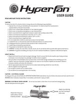
ELECTRONICS OPERATION ALGORITHM
The KSA U (U1) fan is equipped with an electronic speed controller with a TSC electronic thermostat for automatic air flow control
depending on the air temperature.
The electronic speed controller has 2 control knobs: for setting the motor speed and for setting the electronic thermostat.
The light indicator of the thermostat operation is located on the fan cover.
To set the thermostat threshold, turn the thermostat control knob clockwise to increase or counter-clockwise to decrease the temperature
set point.
To set the fan speed, turn the speed control knob in the same way.
The KSA U control algorithm by temperature:
The fan maintains air temperature with an accuracy of 2 °C.
When the air temperature rises to the set temperature, the fan switches to high speed.
If the air temperature drops 2 °C below the set point or if the initial air temperature is lower than the set temperature,
the fan continues to run at low speed.
The KSA U1 control algorithm by timer:
The fan maintains air temperature with high accuracy.
The fan changes its speed more often compared to the previous control algorithm, but the minimum operating time at one speed is at
least 5 minutes.
When the air temperature rises to the set value, the fan switches to maximum speed.
The switching delay timer synchronously starts for 5 minutes.
If the air temperature drops below the set point, the fan speed will change to a lower one only in 5 minutes.
If the initial temperature is lower than the set one, the fan will continue to operate at low speed.
The KSA P fan is equipped with a speed controller that allows turning the fan on/off and smoothly adjusting the air flow rate from
minimum to maximum speed.
KSA U (U1) KSA P
21
22
23
24
25
26
27
28
29
min ma x
~
~
~
t
C
30°C20°C
1
2
1
min max
~
~
~
1 – speed control knob
2 – thermostat control knob
Caution! To reset the fan, disconnect its power supply mains.

8
KSA
www.ventilation-system.com
• Disconnect the unit from power supply prior to any connection, servicing and repair operations.
• Prior to installing the fan make sure the casing has no visible damages and check the integrity of power supply wires. The fan casing
must not contain any foreign objects which can damage the impeller blades.
• Make sure the impeller rotates freely without touching the flange and the casing.
• The fan shall be installed in the air duct with the same diameter.
• Mount the fan in such a way that the arrow on the fan casing matches the air flow direction in the system.
• Install flexible connectors on both sides of the fan (purchased separately).
• Ensure a direct air duct section of at least one air duct diameter long on the inlet side and at least three air duct diameters long on
the outlet side.
• The fan is not a ready to use unit and requires connection to the air ducts.
• Install the fan securely while ensuring free access for maintenance operations.
• The fixing means for attachment to the ceiling such as hooks or other devices shall be fixed with a sufficient strength to withstand
4 times the weight of the ceiling fan.
• When mounting the fan outdoors, protect it against weather impact and water ingress, for example, by mounting a hood over the fan.
• Take steps to prevent back flow of gases from devices using gas and open flames.
MOUNTING SEQUENCE
1. Mark the holes for mounting the fan. 2. Drill the holes according to the markings. 3. Mount the fan on the mounting bracket.
Connect air ducts to the fan.
READ THE USER'S MANUAL BEFORE INSTALLING THE UNIT.
WHILE INSTALLING THE UNIT ENSURE CONVENIENT ACCESS FOR SUBSEQUENT
MAINTENANCE AND REPAIR.
THE UNIT MUST BE MOUNTED ON A PLANE SURFACE.
MOUNTING OF THE UNIT TO AN UNEVEN SURFACE CAN LEAD TO THE UNIT CASING
DISTORTION AND OPERATION DISTURBANCE.
MOUNTING AND SETUP

9
www.ventilation-system.com
POWER OFF THE POWER SUPPLY PRIOR TO ANY OPERATIONS WITH THE UNIT.
THE UNIT MUST BE CONNECTED TO POWER SUPPLY BY A QUALIFIED ELECTRICIAN.
THE RATED ELECTRICAL PARAMETERS OF THE UNIT ARE GIVEN ON THE
MANUFACTURER’S LABEL.
• The unit is rated for connection to 1~230 V/50 Hz power mains.
• The connection must be made using durable, insulated and heat-resistant conductors (cables, wires).
• The actual wire cross section selection must be based on the maximum load current, maximum conductor temperature depending on
the wire type, insulation, length and installation method.
• The external power input must be equipped with an automatic circuit breaker QF built into the stationary wiring to open the circuit in
the event of overload or short-circuit.
• The position of the external automatic circuit breaker must ensure free access for quick power-off of the unit.
• The automatic circuit breaker nominal current must exceed the ventilator current consumption.
• It is recommended to select the rated current of the circuit breaker from the standard series, following the maximum current of the
connected unit.
• The circuit breaker is not included in the delivery set and can be ordered separately.
• The unit must be connected to power mains through a double pole circuit breaker of suitable rating integrated into the fixed wiring
system with opening of contacts at all poles. The gap between the circuit breaker contacts at all poles must be not less than 3 mm.
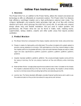
Follow the wiring diagram to connect the fan using the power cable.
L
N
L
QF
N
PE FAN
1~230 V/50 Hz
Designation key:
L, N - connection terminals
PE – ground terminal
QF – automatic circuit breaker
Depending on the model, the fan may be equipped with a power cable with a mains plug.
CONNECTION TO POWER MAINS

10
KSA
www.ventilation-system.com
The technical maintenance includes periodic (once in 6 months ) cleaning of the surfaces from accumulated dust and dirt.
• Disconnect the fan from power mains prior to any maintenance operations.
• Use a soft dry cloth, brush or compressed air to remove dust.
• Carry out wet cleaning using warm water and a mild household detergent. Avoid water splashes on the unit! Do not immerse the
unit in water!
• Do not use aggressive solvents, or sharp objects as they may damage the impeller.
Avoid penetration of water onto the electric parts and the motor.
Wipe the unit surfaces dry after cleaning.
DISCONNECT THE UNIT FROM POWER SUPPLY BEFORE ANY MAINTENANCE
OPERATIONS!
ENSURE THAT THE UNIT IS SWITCHED OFF FROM THE SUPPLY MAINS BEFORE
REMOVING THE GUARD.
TECHNICAL MAINTENANCE

11
www.ventilation-system.com
STORAGE AND TRANSPORTATION REGULATIONS
• Store the unit in the manufacturer’s original packaging box in a dry closed ventilated premise with temperature range
from +5 ˚С to +40 ˚С and relative humidity up to 70 %.
• Storage environment must not contain aggressive vapors and chemical mixtures provoking corrosion, insulation, and sealing
deformation.
• Use suitable hoist machinery for handling and storage operations to prevent possible damage to the unit.
• Follow the handling requirements applicable for the particular type of cargo.
• The unit can be carried in the original packaging by any mode of transport provided proper protection against precipitation and
mechanical damage. The unit must be transported only in the working position.
• Avoid sharp blows, scratches, or rough handling during loading and unloading.
• Prior to the initial power-up after transportation at low temperatures, allow the unit to warm up at operating temperature for at least
3-4 hours.
PROBLEM POSSIBLE REASONS TROUBLESHOOTING
The fan does not start. No power supply.
Make sure that the unit is properly connected to the power
mains and make any corrections, if necessary.
Low air flow.
The ventilation system is soiled
or damaged.
Make sure the air ducts are clean and intact. Clean them if
necessary.
Noise, vibration.
The fan impeller is soiled. Clean the impellers.
The screw connection is loose. Tighten the fastening screws.
TROUBLESHOOTING

12
KSA
www.ventilation-system.com
MANUFACTURER’S WARRANTY
The product is in compliance with EU norms and standards on low voltage guidelines and electromagnetic compatibility. We hereby
declare that the product complies with the provisions of Electromagnetic Compatibility (EMC) Directive 2014/30/EU of the European
Parliament and of the Council, Low Voltage Directive (LVD) 2014/35/EU of the European Parliament and of the Council and CE-marking
Council Directive 93/68/EEC. This certificate is issued following test carried out on samples of the product referred to above.
The manufacturer hereby warrants normal operation of the unit for 24 months after the retail sale date provided the user's observance
of the transportation, storage, installation, and operation regulations. Should any malfunctions occur in the course of the unit operation
through the Manufacturer's fault during the guaranteed period of operation, the user is entitled to get all the faults eliminated by the
manufacturer by means of warranty repair at the factory free of charge. The warranty repair includes work specific to elimination of faults
in the unit operation to ensure its intended use by the user within the guaranteed period of operation. The faults are eliminated by means
of replacement or repair of the unit components or a specific part of such unit component.
The warranty repair does not include:
• routine technical maintenance
• unit installation/dismantling
• unit setup
To benefit from warranty repair, the user must provide the unit, the user's manual with the purchase date stamp, and the payment
paperwork certifying the purchase. The unit model must comply with the one stated in the user’s manual. Contact the Seller for warranty
service.
The manufacturer’s warranty does not apply to the following cases:
• User’s failure to submit the unit with the entire delivery package as stated in the user’s manual including submission with missing
component parts previously dismounted by the user.
• Mismatch of the unit model and the brand name with the information stated on the unit packaging and in the user's manual.
• User’s failure to ensure timely technical maintenance of the unit.
• External damage to the unit casing (excluding external modifications as required for installation) and internal components caused
by the user.
• Redesign or engineering changes to the unit.
• Replacement and use of any assemblies, parts and components not approved by the manufacturer.
• Unit misuse.
• Violation of the unit installation regulations by the user.
• Violation of the unit control regulations by the user.
• Unit connection to power mains with a voltage different from the one stated in the user's manual.
• Unit breakdown due to voltage surges in power mains.
• Discretionary repair of the unit by the user.
• Unit repair by any persons without the manufacturer’s authorization.
• Expiration of the unit warranty period.
• Violation of the unit transportation regulations by the user.
• Violation of the unit storage regulations by the user.
• Wrongful actions against the unit committed by third parties.
• Unit breakdown due to circumstances of insuperable force (fire, flood, earthquake, war, hostilities of any kind, blockades).
• Missing seals if provided by the user’s manual.
• Failure to submit the user’s manual with the unit purchase date stamp.
• Missing payment paperwork certifying the unit purchase.
FOLLOWING THE REGULATIONS STIPULATED HEREIN WILL ENSURE A LONG AND
TROUBLEFREE OPERATION OF THE UNIT.
USER’S WARRANTY CLAIMS SHALL BE SUBJECT TO REVIEW ONLY UPON
PRESENTATION OF THE UNIT, THE PAYMENT DOCUMENT AND THE USER’S MANUAL
WITH THE PURCHASE DATE STAMP.

13
www.ventilation-system.com
CERTIFICATE OF ACCEPTANCE
Unit Type Centrifugal fan in sound insulated casing
Model KSA
Serial Number
Manufacture Date
Quality Inspector’s
Stamp
SELLER INFORMATION
Seller
Seller’s Stamp
Address
Phone Number
E-mail
Purchase Date
This is to certify acceptance of the complete unit delivery with the user’s manual. The warranty terms are
acknowledged and accepted.
Customer’s Signature
INSTALLATION CERTIFICATE
The KSA unit is installed pursuant to the requirements stated in the present user's manual.
Installation Stamp
Company name
Address
Phone Number
Installation
Technician’s Full Name
Installation Date: Signature:
The unit has been installed in accordance with the provisions of all the applicable local and national construction,
electrical and technical codes and standards. The unit operates normally as intended by the manufacturer.
Signature:
WARRANTY CARD
Unit Type Centrifugal fan in sound insulated casing
Seller’s Stamp
Model KSA
Serial Number
Manufacture Date
Purchase Date
Warranty Period
Seller

14
KSA
www.ventilation-system.com

15
www.ventilation-system.com

V42EN-07
/