Simplex 4100ESi Installation guide
- Category
- Fire protection
- Type
- Installation guide

Installation guide
4100ESi
LT0618
Issue
1.1

2

3
Contents
Chapter 1. Introduction ........................................................................................................................... 12
Cabinets overview .............................................................................................................................................. 12
Hardware overview ............................................................................................................................................ 12
CPU and motherboard features............................................................................................................... 13
PDI backplane features .................................................................................................................................. 14
Legacy card and features ............................................................................................................................ 15
System features ...................................................................................................................................................... 15
Chapter 2. 4100ESi Compact Panel .............................................................................................. 16
Mounting the cabinet ....................................................................................................................................... 16
Mains wiring ........................................................................................................................................................... 17
Batteries .................................................................................................................................................................... 17
Adding a MX Loop card ................................................................................................................................. 18
Flat mounting ....................................................................................................................................................... 18
Bracket mounting ............................................................................................................................................. 18
Adding other PDI cards ................................................................................................................................ 18
Adding a Network Interface Card ......................................................................................................... 20
Adding a T-GEN 60 .............................................................................................................................................. 21
Mounting .................................................................................................................................................................. 21
Wiring .......................................................................................................................................................................... 22
Configuration ....................................................................................................................................................... 23
Adding a T-GEN 50 .............................................................................................................................................. 24
Mounting .................................................................................................................................................................. 24
Wiring .......................................................................................................................................................................... 24
Configuration ....................................................................................................................................................... 26
More Power ........................................................................................................................................................... 26
Adding fan controls or displays ................................................................................................................. 27
General ..................................................................................................................................................................... 27
Adding an ASE brigade transmission unit ...................................................................................... 30
Adding a NTFast brigade transmission unit ................................................................................... 30
Chapter 3. 8U and 15U Expansion Cabinets ........................................................................... 31
Mounting the cabinet ................................................................................................................................... 31
Connecting to the main panel .............................................................................................................. 33
Adding a MX Loop Card ............................................................................................................................. 34

4
Flat mounting ........................................................................................................................................................................ 34
Bracket mounting .............................................................................................................................................................. 35
Adding other PDI cards ................................................................................................................................ 35
Adding legacy cards ..................................................................................................................................... 36
Adding a T-GEN 60 in an Expansion Cabinet ............................................................................. 40
Mounting in 15U expansion cabinet ................................................................................................................... 40
Mounting in 8U expansion cabinet...................................................................................................................... 40
Wiring ........................................................................................................................................................................................... 41
Adding a T-GEN 50 on a legacy bracket ....................................................................................... 41
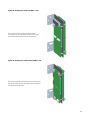
Chapter 4. Using the Dual PDI bracket ....................................................................................... 42
PDI card mounting options ........................................................................................................................ 42
Bracket mounting options .......................................................................................................................... 45
Panel connection ............................................................................................................................................. 47
Chapter 5. Large cabinets - 28U or 40U ...................................................................................... 48
Mounting the cabinet ....................................................................................................................................... 48
Mains wiring 50
Adding a MX Loop Card ................................................................................................................................ 50
Flat mounting 50
Adding other PDI cards ................................................................................................................................... 52
Adding legacy cards ........................................................................................................................................ 52
Adding a power supply ................................................................................................................................... 54
ME0504 APS ............................................................................................................................................................ 54
ME0470 auxiliary supply ................................................................................................................................ 55
Adding a T-GEN 60 or T-GEN 120 .......................................................................................................... 56
Mounting in an Expansion Bay ................................................................................................................................ 56
Wiring in the Bay ................................................................................................................................................................. 56
Mounting a T-GEN User Interface ......................................................................................................................... 59
Adding a bay ....................................................................................................................................................................... 59
Network card installation ............................................................................................................................... 59
Adding fan controls or displays ................................................................................................................. 59
Adding an ASE ........................................................................................................................................................ 60
Chapter 6. Network card installation ............................................................................................ 62
Adding a network card ................................................................................................................................... 62
Network card settings .................................................................................................................................... 63

5
On the CPU motherboard .......................................................................................................................................... 63
On the NIC .............................................................................................................................................................................. 63
Wired Media card settings ......................................................................................................................... 64
Fibre optic media card settings ............................................................................................................. 64
Mounting media cards .................................................................................................................................... 65
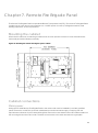
Chapter 7. Remote Fire Brigade Panel ....................................................................................... 66
Mounting the cabinet ....................................................................................................................................... 66
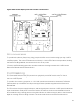
Cabinet connections ........................................................................................................................................ 66
Mains power .......................................................................................................................................................... 66
RUI communications ....................................................................................................................................... 67
Commissioning ....................................................................................................................................................... 67
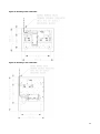
Chapter 8. Remote Transponder Unit (RTU) ............................................................................. 68
Mounting the cabinet ....................................................................................................................................... 68
Cabinet connections ........................................................................................................................................ 70
Mains power .......................................................................................................................................................... 70
RUI communications ....................................................................................................................................... 70
Commissioning ....................................................................................................................................................... 70
Adding PDI cards .................................................................................................................................................. 70
Adding legacy cards ........................................................................................................................................ 71
Appendix A System specifications ..................................................................................................... 73
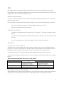
Appendix B Cable characteristics .................................................................................................... 76
MX Addressable Loop....................................................................................................................................... 76
RUI 77
Class A operation .............................................................................................................................................. 77
Network ..................................................................................................................................................................... 77
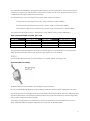
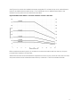
Copper line characteristics ....................................................................................................................................... 77
Fibre Optic Cable Characteristics ........................................................................................................................ 77
IDNet ........................................................................................................................................................................... 78
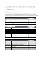
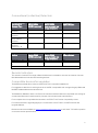
Appendix C Compatible actuating devices ............................................................................. 80
MX Addressable Devices ............................................................................................................................ 80
Conventional (collective) Detectors ................................................................................................. 81
Remote Indicators ............................................................................................................................................ 81
Compatible devices for upgrades ...................................................................................................... 81
Compatible special hazard devices ................................................................................................. 82

6
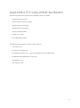
Appendix D Compatible batteries .................................................................................................... 83
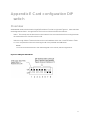
Appendix E Card configuration DIP switch ............................................................................... 84
Overview 84
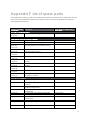
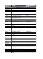
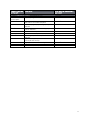
Appendix F List of spare parts............................................................................................................... 86
Appendix G Checking system wiring ............................................................................................... 89
Using the Volt/Ohm Meter ......................................................................................................................... 89
Appendix H 4100ESi functions ............................................................................................................... 91
Optional functions in AS7240.2 ................................................................................................................................ 91
Functions in other parts of AS 7240 ...................................................................................................................... 92
Ancillary functions not required by AS 7240.2 ............................................................................................. 92

7
Cautions, warnings, and regulatory
information
Non-Disclosure Agreement
Johnson Controls International (THE COMPANY) and the User of this/these document(s) desire to share
proprietary technical information concerning electronic systems.
For this reason the company is disclosing to the User information in the form of this/these document(s). In as
much as the company considers this information to be proprietary and desires that it be maintained in
confidence, it is hereby agreed by the User that such information shall be maintained in confidence by the User
for a period of TEN YEARS after the issue date and only be used for the purpose for which it was supplied.
During this period, the User shall not divulge such information to any third party without the prior written
consent of the company and shall take reasonable efforts to prevent any unauthorised disclosure by its
employees. However, the User shall not be required to keep such information in confidence if it was in their
possession prior to its receipt from the company; if it is or becomes public knowledge without the fault of the
User; or the information becomes available on an unrestricted basis from a third party having a legal right to
disclose such information.
The User's receipt and retention of this information constitutes acceptance of these terms.
This information is copyright and shall not be reproduced in any form whatsoever.
End User Liability Disclaimer
The 4100ESi Fire Alarm System provides a configuration programming facility, which may be accessed via a
programming computer using a “dongle”. Because this programming facility allows the user to define in detail
the operation of the 4100ESi System being customised, changes may be made by the user that prevent this
installation from meeting statutory requirements.
The Company, therefore cannot accept any responsibility as to the suitability of the functions generated by the
user using this programming facility.

8
READ AND SAVE THESE INSTRUCTIONS
Follow the instructions in this installation manual. These instructions must be followed to avoid damage to this
product and associated equipment. Product operation and reliability depends upon proper installation.
DO NOT INSTALL ANY SIMPLEX® PRODUCT THAT APPEARS DAMAGED
Upon unpacking your Simplex product, inspect the contents of the carton for shipping damage. If
damage is apparent, immediately file a claim with the carrier and notify your Simplex product
supplier.
SAFETY HAZARD
The 4100ESi CPU Card includes a lithium battery. There is a very low danger of explosion if the
battery is incorrectly replaced. Replace only with the same or equivalent type recommended by the
manufacturer. Dispose of used batteries according to the manufacturer’s instructions.
ELECTRICAL HAZARD
Disconnect electrical field power when making any internal adjustments or repairs. All repairs
should be performed by a representative or authorized agent of your local Simplex product
supplier.
STATIC HAZARD
Static electricity can damage components. Therefore, handle as follows:
⋅ Earth yourself with a suitable static strap or similar before opening or installing components.
⋅ Prior to installation, keep components wrapped in anti-static material at all times.
EYE SAFETY HAZARD
Under certain fibre optic application conditions, the optical output of this device may exceed eye
safety limits. Do not use magnification (such as a microscope or other focusing equipment) when
viewing the output of this device.
RADIO FREQUENCY ENERGY
This equipment generates, uses, and can radiate radio frequency energy and if not installed and
used in accordance with the instruction manual, may cause interference to radio communications.
It has been tested and found to comply with the limits defined in AS/NZS CISPR22:2010. In a
domestic environment this product may cause radio interference, in which case the user may be
required to take adequate measures.

9
SULFURIC ACID WARNING
The batteries contain sulfuric acid, which can cause severe burns to the skin and eyes and can
destroy fabric. Replace any leaking or damaged battery while wearing appropriate protective gear.
If you come in contact with sulfuric acid, immediately flush skin or eyes with water for 15 minutes
and seek immediate medical attention.
SYSTEM REACCEPTANCE TEST AFTER SOFTWARE CHANGES
To ensure proper system operation, this product must be tested in accordance with AS 1670.1
after any programming operation or change in site-specific software. Reacceptance testing is
required after any change, addition or deletion of system components, or after any modification,
repair or adjustment to system hardware or wiring.
All components, circuits, system operations, or software functions, known to be affected by a
change must be 100% tested. In addition, to ensure that other operations are not inadvertently
affected, at least 10% of initiating devices that are not directly affected by the change, up to a
maximum of 50 devices, should also be tested and proper system operation verified.
SOFTWARE VERSION COMPATIBILITY
Verify 4100ESi System Programmer, Executive, and Slave Software compatibility when installing
or replacing system components. Refer to the Solutions Bulletin SB11002 for more information.

10
Copyright and trademarks
©2018 Johnson Controls International. All Rights Reserved.
All specifications and other information shown were current as of document revision date, and are subject to
change without notice.
Johnson Controls, Simplex, the Simplex logo, MAPNET II, IDNet, TrueAlarm, SmartSync, WALKTEST, MINIPLEX,
and TrueAlert are trademarks of Johnson Controls International Services or its affiliates in the U.S. and/or other
countries. VESDA is a trademark of Xtralis.
Simplex fire alarm technology is protected by the following U.S. Patent Numbers:
TrueAlarm analog smoke detection: 5,155,468; 5,173,683 and 5,543,777. IDNet and MAPNET II
addressable communications; 4,796,025. TrueAlert addressable notification; 6,313,744 and 6,426,697.
SmartSync horn/strobe control; 6,281,789.

11
Other references
More information about the setup, operation, and maintenance of the 4100ESi Fire Alarm panel can be found
in the following documents:
⋅ LT0619 4100ESi Programming Manual - for configuring the system software and site specific data files.
⋅ LT0617 4100ESi Operator Manual - for basic operation of the panel using the touchscreen interface.
⋅ LT0432 4100ESi Australian Wiring Diagrams - for connection of field equipment to the panel and
interconnection of panels for networking.
⋅ LT0620 4100ESi Service and Upgrade Manual - for service and maintenance operations, and details on
how to upgrade earlier versions of the 4100 series of panels to 4100ESi.
Individual system components such as slave cards, field devices, and detectors are supplied with installation
information specific to the component. Some of that information is repeated in this installation manual.
⋅ LT0614 4100ESi Brigade Interface Bracket Installation Instructions - describes fitting the ME0512
Centaur and ME0513 WA/ASE brackets.
⋅ LT0615 Simplex Media Card Installation Instructions - describes fitting and wiring the NIC media cards.
⋅ LT0622 Dual Loop Card Bracket Installation Instructions - describes fitting the ME0516 Dual Loop Card
bracket.
⋅ LT0624 NT Brigade Door Installation Instructions - describes fitting and wiring the FP1093 NT 6U Door.
⋅ LT0627 4100ESi 8U and 15U Expansion Cabinet Installation Instructions – describes installing the 8U
and 15U expansion cabinets.
⋅ LT0629 4100ESi Remote Fire Brigade Panel Installation Instructions – describes installing and wiring the
FP1048 Remote Fire Brigade Panel.
⋅ LT0632 4100ESi 7U Display Door Installation Instructions – describes fitting the 7U display door in
various cabinets.
⋅ LT0633 4100ESi Fan Control Setback Bracket Installation Instructions –describes fitting the fan control
module in large cabinets.
⋅ LT0638 4100ESi MX Loop Card Installation Instructions – describes installation, configuration, and wiring
of the MX Loop card.

12
Chapter 1. Introduction
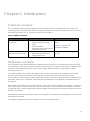
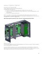
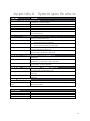
Cabinets overview
The 4100ESi Fire Alarm panel is available in a range of cabinets that are compatible with the 19 inch rack
mounting system. The cabinets are referred to using their respective vertical sizes expressed in the units of this
rack mounting system (1U = 1.752 inches or 44.5mm), see Table 1.
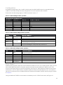
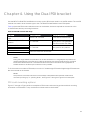
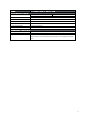
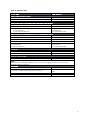
Table 1. 4100ESi cabinet sizes
Cabinet
Description
Link to installation details
15U compact cabinet.
8U cabinet.
⋅
Common size of panel.
⋅ Titania powder coat ripple
finish.
⋅ Optional window.
⋅ Compatible color
and knockout
cable access location.
Chapter 2, 4100ESi Compact
Panel.
Chapter 3, 8U and 15U
Expansion Cabinets.
28U build-to-order cabinet.
40U build-to-order cabinet.
⋅
Additional display space.
⋅ Additional internal capacity.
⋅ Cream wrinkle color.
Chapter 5, Large cabinets - 28U
or 40U.
Hardware overview
The 4100 series of Fire Alarm panels has a modular internal construction. A 4100ESi system consists of one
or more cabinets. Each cabinet contains between one and four bays. Each bay contains up to 8 modules. Each
module provides a particular function such as power supply, detector interfaces, output relays, or NACs,
networking, and so on.
It is usually possible to fit modules and brackets in any location within a bay or on a gearplate in any cabinet.
However, some module and bracket combinations have physical limitations. Some fitting options are
recommended, some fitting options are possible with conditions, and some fittings options are impossible. This
particularly applies to the 15U panel. These limitations are described in more detail in the relevant sections of
this manual.
Each cabinet can contain one or more display doors. There are two types: a hinged 7U InfoAlarm+ touchscreen
door, and a hinged 7U LED indicator door. Customisation of the 7U LED indicator door is possible, if required,
by replacing some or all of the eight blank sections supplied in the basic panel with alternative function controls,
indicators, or modules.
All mandatory controls and indicators must be on one cabinet, or in cabinets mounted adjacent to each other as
described in this manual.
It is possible to fill gaps in the front of the cabinets with 3U or 4U blank panels.

13
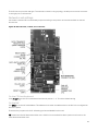
CPU and motherboard features
The core of the 4100ESi system is the CPU card, also known as the master card. This is connected by an
internal communications bus to one or more slave cards. The slave cards provide specific functions controlling
the overall system operation such as power supply, user interface, detector circuits, output relays, notification
circuits, and so on.
Every 4100ESi system has one CPU. The CPU card must connect to the CPU motherboard using the edge
connector.
Figure1. Mounting the CPU card and motherboard
For more information about terminals, links, and indicators on the CPU card and motherboard, see Network
card settings.

14
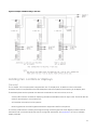
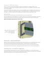
PDI backplane features
The Power Distribution Interface (PDI) is a backplane running across the width of each bay. The PDI supports the
slave cards that use the PDI format. These cards mount flat and connect to the sockets on the PDI backplane for
power and communications. PDI slave cards are available in various sizes, based on a minimum size of 4 inch x
5 inch.
Figure 2. PDI card mounted on backplane in a bay
The bay back planes are linked together with compatible 4-way looms distributing power and communications.
The 4-way looms are available in the following lengths:
⋅ 0.6 meters, part number 734-008.
⋅ 1.3 meters, part number LM0592.
⋅ 2.4 meters, part number 734-075.

15
Legacy card and features
There are four other legacy cards formally listed for use with new 4100ESi systems, as well as a larger number
of older legacy cards which are compatible with 4100ESi but are not formally listed for new installations.
Each legacy card has a matching motherboard that is mounted in the same way as the CPU motherboard
shown in Figure1 above. The motherboards have matching connectors that distribute power and
communications signals.
Depending on the type of cabinet, the legacy cards are mechanically secured by retaining bars fitted to the bay
ends, to a display door, or to the cabinet.
System features
The 4100ESi is an AS7240.2 compliant fire alarm panel. In addition to providing mandatory functions, the
4100ESi also provides a number of optional AS 7240.2 functions, functions relating to other parts of
AS 7240, specifically AS 7240.4, and functions that are additional to those required by AS 7240.2. These
functions are listed in Appendix H, 4100ESi functions.

16
Chapter 2. 4100ESi Compact Panel
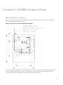
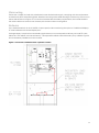
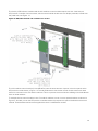
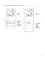
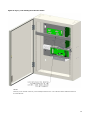
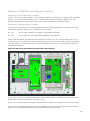
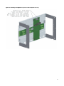
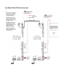
Mounting the cabinet
Mount the 15U cabinet vertically on four M8 studs or screws. Space the screws or studs 415 millimeters
horizontally and 450 millimeters vertically.
Figure 3. 15U compact cabinet mounting and mains wiring
AS1670.1 requires a clear space of 1 meter in front, and 0.5 meters on each side of all cabinets that are to be
used by emergency personnel. AS 1670.1 requires that the main touchscreen display (FBP), and all fan
controls are between 750 millimeters and 1850 millimeters above the floor.

17
Mains wiring
Ensure the 4100ESi is wired with a dedicated current limited mains supply, complying with the requirements
outlined in AS/NZS 3000 Wiring Rules. Install the incoming mains cable entering the cabinet top or bottom on
the left side as shown in Figure 3. To meet the Australian electrical safety requirements, the outside sheath of
the mains cable must continue into the body of the mains outlet mounting block.
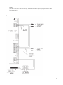
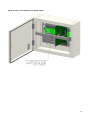
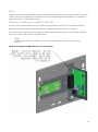
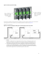
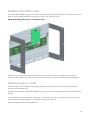
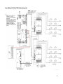
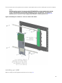
Batteries
Up to 33Ah batteries fit in the 4100ESi Compact panel, without restricting the option to fit additional displays
or other hardware on the lower display door.
If a larger battery is required to meet standby requirements, mount an expansion cabinet, part code FP1029,
below the 15U cabinet to house this battery. This expansion cabinet can hold a battery of up to 80Ah. Figure 4
shows the battery installation for this situation.
Figure 4. Connection of batteries in the expansion cabinet

18
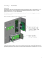
Adding a MX Loop card
One MX loop card is supplied with the 4100ESi Compact panel as standard. This supports one loop of up to
250 MX addressable devices.
Use part number 4100-6077AU to purchase an additional loop card. There is mounting space for one
additional MX loop card of either type.
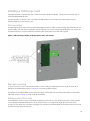
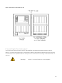
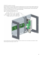
Flat mounting
The MX Digital Loop Card mounts on the PDI backplane of the 4100ESi Compact Panel, and is fastened to the
support pillars with the screws supplied in the MX Digital Loop Card kit. Mount the MX Digital Loop Card in the
unused PDI position, with the orientation matching the existing MX Loop card, see Figure 5.
Figure 5. LIM assembly mounted on PDI backplane in the 15U cabinet
Bracket mounting
To fit up to four 4100-6077AU MX loop cards in the 4100ESi Compact panel mount a pair of cards on an
ME0516 Dual PDI bracket, refer to Chapter 4, Using the Dual PDI bracket.
The ME0516 Dual PDI bracket can be used for a range of PDI cards. For more information about compatible
PDI cards, refer to Chapter 4, Using the Dual PDI bracket.
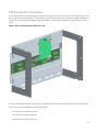
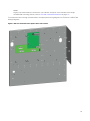
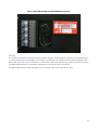
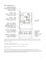
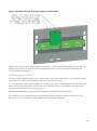
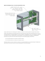
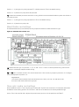
Adding other PDI cards
Other PDI slave cards fit on the unused PDI backplane positions in the 15U cabinet if required. There is space
for two additional standard PDI cards; one up and one down, or a single dual height PDI card such as the
4100-6077AU MX Loop Card. Each card plugs into a socket on the backplane, and is secured with the screws
supplied with the card, see Figure 6.

19
Note:
Legacy style cards cannot be fitted in the 15U cabinet, except for a CPU and NIC in the single
motherboard mounting position, refer to CPU and motherboard features on page 13.
For information about wiring the cards refer to the appropriate wiring diagrams in LT0432 4100ESi Field
Wiring Diagrams.
Figure 6. PDI card mounted on backplane in the 15U cabinet

20
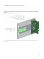
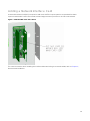
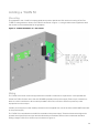
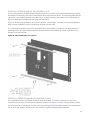
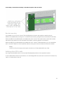
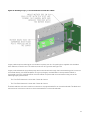
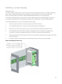
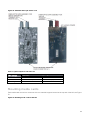
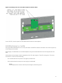
Adding a Network Interface Card
A Network Interface Card (NIC) is required to add the 4100ESi Compact panel to a networked fire alarm
system. Install the NIC card in the unused, left hand edge connector position on the CPU motherboard.
Figure 7. 4100-6078 NIC in the 15U cabinet
For more information about installing the media modules and wiring the network cables, refer to Chapter 6,
Network card installation.
Page is loading ...
Page is loading ...
Page is loading ...
Page is loading ...
Page is loading ...
Page is loading ...
Page is loading ...
Page is loading ...
Page is loading ...
Page is loading ...
Page is loading ...
Page is loading ...
Page is loading ...
Page is loading ...
Page is loading ...
Page is loading ...
Page is loading ...
Page is loading ...
Page is loading ...
Page is loading ...
Page is loading ...
Page is loading ...
Page is loading ...
Page is loading ...
Page is loading ...
Page is loading ...
Page is loading ...
Page is loading ...
Page is loading ...
Page is loading ...
Page is loading ...
Page is loading ...
Page is loading ...
Page is loading ...
Page is loading ...
Page is loading ...
Page is loading ...
Page is loading ...
Page is loading ...
Page is loading ...
Page is loading ...
Page is loading ...
Page is loading ...
Page is loading ...
Page is loading ...
Page is loading ...
Page is loading ...
Page is loading ...
Page is loading ...
Page is loading ...
Page is loading ...
Page is loading ...
Page is loading ...
Page is loading ...
Page is loading ...
Page is loading ...
Page is loading ...
Page is loading ...
Page is loading ...
Page is loading ...
Page is loading ...
Page is loading ...
Page is loading ...
Page is loading ...
Page is loading ...
Page is loading ...
Page is loading ...
Page is loading ...
Page is loading ...
Page is loading ...
Page is loading ...
Page is loading ...
Page is loading ...
-
 1
1
-
 2
2
-
 3
3
-
 4
4
-
 5
5
-
 6
6
-
 7
7
-
 8
8
-
 9
9
-
 10
10
-
 11
11
-
 12
12
-
 13
13
-
 14
14
-
 15
15
-
 16
16
-
 17
17
-
 18
18
-
 19
19
-
 20
20
-
 21
21
-
 22
22
-
 23
23
-
 24
24
-
 25
25
-
 26
26
-
 27
27
-
 28
28
-
 29
29
-
 30
30
-
 31
31
-
 32
32
-
 33
33
-
 34
34
-
 35
35
-
 36
36
-
 37
37
-
 38
38
-
 39
39
-
 40
40
-
 41
41
-
 42
42
-
 43
43
-
 44
44
-
 45
45
-
 46
46
-
 47
47
-
 48
48
-
 49
49
-
 50
50
-
 51
51
-
 52
52
-
 53
53
-
 54
54
-
 55
55
-
 56
56
-
 57
57
-
 58
58
-
 59
59
-
 60
60
-
 61
61
-
 62
62
-
 63
63
-
 64
64
-
 65
65
-
 66
66
-
 67
67
-
 68
68
-
 69
69
-
 70
70
-
 71
71
-
 72
72
-
 73
73
-
 74
74
-
 75
75
-
 76
76
-
 77
77
-
 78
78
-
 79
79
-
 80
80
-
 81
81
-
 82
82
-
 83
83
-
 84
84
-
 85
85
-
 86
86
-
 87
87
-
 88
88
-
 89
89
-
 90
90
-
 91
91
-
 92
92
-
 93
93


Simplex 4100ESi Installation guide
- Category
- Fire protection
- Type
- Installation guide
Ask a question and I''ll find the answer in the document
Finding information in a document is now easier with AI
Related papers
-
 Simplex 4100 Classic User manual
-
 Simplex MINIPLEX 4100ES Series Installation & Maintenance
-
 Simplex 4100ES-S1 Installation & Maintenance
-
Tyco 4100U-S1 User manual
-
Simplex 4009 IDNet NAC Extender User manual
-
 Simplex 4090-9116 Installation Instructions Manual
-
 Simplex MINIPLEX 4100ES Series Quick start guide
-
Tyco 4100U User manual
-
 Simplex SafeLINC 4100 User manual
-
 Simplex 4100ES Operating Instructions Manual


Other documents
-
Mirai MF3210 Datasheet
-
Morning Industry HKK-01SN Installation guide
-
Whirlpool ASE 526 Installation guide
-
-
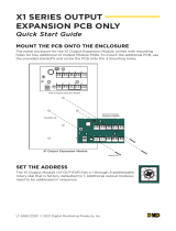 Digital Monitoring Products X1 Series Output Expansion PCB Only Quick start guide
-
 Morning Industry QF-01P Operating instructions
-
Tyco 4100ES-S1 Installation guide
-
Acorn Ethernet 3 Installation Addendum
-
 SILENT KNIGHT SK-NIC-KIT User manual
-
Morning Industry HF-01AQ Operating instructions


