Page is loading ...

lIortec
WHEN
YOU
NEED
HUMIDITY
GH Series
Gas Fired Humidifier
Inst lIation, User &
Maintenance Guide
FOR YOUR SAFETY:
Do not store or use gasoline or other flammable vapors and liquids
in
the vicinity of this
or any other appliance.
WHAT
TO DO IF YOU
SMELL
GAS:
Do not try to light any appliance.
Do not touch any electrical switch; do not use any telephone
in
your building.
Immediately call your gas supplier from a neighbor's telephone.
Follow the gas supplier's instructions. If you can not reach your gas supplier, call the fire
department.
WARNING:
Improper installation,
adjustment, alteration, service or maintenance can cause injury or
property damage. Refer to this manual. For assistance or additional information consult
a qualified installer, service agency, or the gas supplier.
WARNING:
causin
IMPORTANT: Read and save this guide for future
reference. This guide to
be
left with equipment owner.
Form 98-272

Table
Of
Contents
WARNING
1
- RECEIVING & UNPACKING EQUIPMENT. . . . . . . . . . . . . . . . . . . . .
..
.
· . . . 1
- GENERAL SPECIFICATIONS
.............................
.
·
...
2
- INTRODUCTiON . . . . . . . . . . . . . . . . . . . . . . . . . . . . . . . . . . .
..
·
...
2
- LOCATING AND MOUNTING
...............................
.
. . 2
3
- GAS PIPING . . . . . . . . . . . . . . . . . . . . . . . . . . . . . . . . . . . . . . .
..
.
....
4
- GAS PRESSURE SPECIFICATIONS . . . . . . . . . . . . . . . . . . . . . . . . . .
..
.
....
5
~
VENTING.
. . . . . . . . . . . . . . . . . . . . . . . . . . . . . . . . . . . . . . . . .
...
5
-
ADDITIONAL REQUIREMENTS WHEN VENTING THROUGH A SIDEWALL . .
...
6
- ELECTR
ICAL.
. . . . . . . . . . . . . . . . . . . . . . . . . . . . . . . . . . . . . .
..
. . . . 6
-
PRIMARY
WIRING.
. . . . . . . . . . . . . . . . . . . . . . . . . . . . . . . . . . . .
...
6
- LOW VOLTAGE CONTROL WIRING (See external wiring diagrams
in
this manuaL). .
..
.
...
6
-On/Off Controls
(B
Models) . . . . . . . . . . . . . . . . . . . . . . . . . . . . . .
..
.
...
6
-
MODULATION CONTROLS
(P
MODELS ONLY) . . . . . . . . . . . . . . . . . . . .
..
.
...
7
- BLOWER PACKS. . . . . . . . . . . . . . . . . . . . . . . . . . . . . . . . . . . . . . . . . . . 7
-
STEAM DISTRIBUTORS FOR DUCTED APPLICATIONS. . . . . . . . . . . . . . . .
..
.
...
8
-
PLUMBING.
. . . . . . . . . . . . . . . . . . . . . . . . . . . . . . . . . . . . . . . . . .
...
9
- WATER
SUPPLY
LINE.
. . . . . . . . . . . . . . . . . . . . . . . . . . . . . . . . .
..
.
...
10
- DRAIN
LINE.
. . . . . . . . . . . . . . . . . . . . .
..
. . . . . . . . . . . . . . . . . . . . . . . . 10
- STEAM LINE . . . . . . . . . . . . . . . . . . . . . . . . . . . . . . . . . . . . . . . . . 10
-
WATER TRAP
..................................
.
-
CONDENSATE RETURN LINE
.........................
.
- CONTROL INSTALLATION
...........................
.
OPERATION
- WATER LEVEL CONTROL
.........
.
-
SEQUENCE OF OPERATION . . . . . . . . . . . . . . . . . . . . . . . .
....
12
12
13
13
13
13
- START
UP
PROCEDURE. . . . . . . . . . . . . . . . . . . . . . . . . . . . . . . . . 14
-
FILLING THE SYSTEM . . . . . . . . . . . . . . . . . . . . . . . . . . . . . . . .
..
.
....
14
-
TESTING THE IGNITION SAFETY SHUT-OFF
.............................
14
-
BLOWER PACK OPERATION
.............................
.
- SAFETY INSTRUCTIONS
............
.
MAINTENANCE
- DRAINING THE TANK . . . . . . . . . . . . . . . . . . . . . . . . . . . . .
..
.
-
CLEANING THE STAINLESS STEEL TANK
....................
.
..
'
..
14
.
...
14
14
14
14

- COMBUSTION
BLOWER.
. . . . . .
- BURNER
..............
.
- BURNER REMOVAUINSPECTION
..
- ADJUSTMENTS/REPLACEMENTS OF COMPONENTS.
-Gas Valve Replacement
.....
-Hot Surface Igniter Replacement.
-
Ignition Module Replacement
-Transformer Replacement. . . .
-Air Switch Replacement . . . . .
-Combustion Air Blower Replacement .
-Tank Replacement.
.........
.
- BLOWDOWN CALIBRATION
......
.
- MANUAL STEAM OUTPUT ADJUSTMENT
(B
MODELS)
..
- SERVICING THE UNIT
..
15
15
15
15
15
15
16
16
16
16
16
16
16
17
- FAULT
CONDITIONS.
. . . . 17
-
SERVICE
CHECKS.
. . . . . 17
-
TROUBLESHOOTING GUIDE 18
- GH REPLACEMENT PARTS . . . . . . . . . . . . . . . . . . . . . . . . . . . . . . . . . . . . 19-22
- GH B/P EXTERNAL
WIRING DIAGRAMS . 23
- GHB 100 INTERNAL WIRING DIAGRAM.
·
24
- GHP 100 INTERNAL WIRING DIAGRAM.
· 25
- GHB 200 INTERNAL WIRING DIAGRAM.
· 26
- GHP 200 INTERNAL WIRING DIAGRAM.
·
27
- GHB
400 INTERNAL WIRING DIAGRAM.
·
28
- GHP
400 INTERNAL WIRING DIAGRAM.
·
29

WARNING
..
Improper installation, adjustment, alteration,
service, maintenance, or use can cause carbon
monoxide poisoning, an explosion, fire,
electrical
shock, or other conditions which may cause
personal injury or property damage. Consult a
qualified installer, service agency, local gas
supplier, or your distributor or branch for
information or assistance. The qualified
installer
or agency must use only factory authorized and
listed kits
or
accessories when modifying this
product. A failure to
follow this warning can
cause
electrical shock, fire, personal injury, or
death.
..
Should overheating occur, or the gas fail to shut
off, shut off the manual gas valve to the appliance
before shutting off the electrical
supply.
..
Do not use this appliance if any part has been
under water.
Immediately call a qualified service
technician to inspect the appliance and to replace
any part of the control system and any gas
control which has been under water.
This
installation guide has been designed to
provide assistance when
installing, mounting, and
sizing a GH
Series humidifier. Actual on site
application may vary. Consult Technical Services or
your
local NORTEC representative.
RECEIVING & UNPACKING EQUIPMENT
1.
Check packing slip to ensure ALL material has
been delivered.
2.
All material shortages are
to
be
reported to
NORTEC within 48 hours from receipt of
goods.
NORTEC assumes no responsibility
for any
material shortages beyond this period.
3.
Inspect shipping boxes for damage and note
on shipping waybill accordingly.
4.
After unpacking, inspect equipment for
damage and
if
damage is found, notify the
shipper
promptly.
5.
All
NORTEC products are shipped
on
an
F.O.B. factory basis. Any and all damage,
breakage or
loss claims are to
be
made
directly to the shipping company.
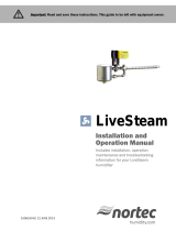
Condensate Steam
Return
II
Outlet
Figure
#1
Vent Can Be From The
Top
Or The Back (GH 100 only)
1 Power And
i--
Control Wiring
i---
Water Input
Line
I---
Gas Input
Line
1:::::::=========:::±:::====l1---
Drain
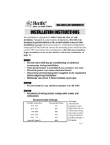
PRODUCT LINE
(Gas Fired Humidifier)
B = BASIC (On/Off)
P
= MODULATING
MC
= DIGITAL CONTROLLER
c/w KEYPAD
PEAK STEAM OUTPUT 100
(lbs/hr) Normal Altitude 200
FUEL
N
= NATURAL GAS
P
= PROPANE GAS
DEIONIZED
WATER
OPTION
HIGH ALTITUDE
400
GH
B 100 N
01
HA
....
~-------------------
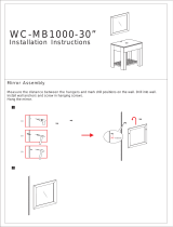
MODEL
GH
100 SPECIFICATIONS
ALTITUDE
FUEL BLOWER
INPUT ORIFICE
STEAM
MANIFOLD
AIR
SHIPPING
OPERATING
(FT)
SPEED
(BTUH)
SIZE
pRILL
CAPACITY
PRESS.
IN
ORIFICE WEIGHT WEIGHT
SI
E) (LBS/HR)
W.C.
DIAMETER
(LBS)
(LBS)
NORMAL
NATURAL
MAX
119,000
E 100 -0.2 1.062"
300 500
(0-2000)
GAS MIN 65,000
E 50
-0.2
1.062"
HIGH
NATURAL MAX
107,000
E
90
-0.2
1.062"
300 500
(2000-4500)
GAS
MIN 58,500
E 45
-0.2
1.062"
NORMAL
PROPANE
MAX
119,000
9
100
-0.2
1.062"
300
500
(0-2000)
(LP GAS)
MIN 65,000
9 50
-0.2 1.062"
HIGH
PROPANE
MAX 107,000
9
90 -0.2 1.062"
300 500
(2000-4500)
(LP GAS)
MIN
58,500
9 45
-0.2 1.062"
- 1 -

MODEL GH 200 SPECIFICATIONS
ALTITUDE
FUEL
BLOWER INPUT ORIFICE STEAM MANIFOLD
AIR
SHIPPING
OPERATING
(FT) SPEED
(BTU
H)
SIZE
pRILL
CAPACITY PRESS. IN
ORIFICE WEIGHT WEIGHT
(MODEL)
SI
E) (LBS/HR) W.C.
DIAMETER
(LBS)
(LBS).
NORMAL
NATURAL
MAX
238,000 E 200 -0.2
I
1.062"
350
660
MIN (S,P)
119,000
E 100
-0.2 1.062"
(0-2000)
GAS
MIN
(MC)
65,000 E
50
-0.2 1.062"
HIGH
NATURAL
MAX
214,000 E
180 -0.2 1.062"
350 660
MIN (S,P)
107,000
E 90
-0.2 1.062"
(2000-4500)
GAS
MIN
(MC)
58,500 E 45 -0.2 1.062"
NORMAL
PROPANE
MAX
238,000
9 200
-0.2 1.062"
350 660
MIN (S,P)
119,000
9 100
-0.2 1.062"
(0-2000)
(LP GAS)
MIN
(MC)
65,000 9 50
-0.2
1.062"
HIGH
PROPANE
MAX
214,000
9
180
-0.2
1.062"
350 660
MIN (S,P)
107,000
9 90
-0.2 1.062"
(2000-4500)
(LP GAS)
MIN
(MC)
58,500 9 45
-0.2 1.062"
MODEL
GH 400 SPECIFICATIONS
ALTITUDE
FUEL BLOWER
INPUT ORIFICE
(FT) SPEED
(BTUH)
SIZE
~DRILL
(MODEL)
SI
E)
NORMAL
NATURAL
MAX
476,000
MIN (S,P)
238,000
(0-2000) GAS MIN
(MC)
65,000
HIGH
NATURAL MAX
428,000
MIN (S,P)
214,000
(2000-4500)
GAS MIN
(MC)
58,500
NORMAL
PROPANE MAX
476,000
MIN (S,P)
238,000
(0-2000)
(LP GAS)
MIN
(MC)
65,000
HIGH
PROPANE
MAX
428,000
MIN (S,P)
214,000
(2000-4500)
(LP GAS) MIN (MC)
58,500
GENERAL SPECIFICATIONS
INTRODUCTION
The NORTEC GH Series humidifier
is
a
completely new patented design based
on
leading
edge technology. The GH
is
designed to provide
clean steam humidification at
an
economical price.
E
E
E
E
E
E
9
9
9
9
9
9
Available for normal altitude (0-2000' elevation) or
for high altitude
(2000-4500' elevation) applications.
LOCATING AND MOUNTING
GH
Series humidifiers are designed to mount
on
a
suitable
wall (GH 100 only), vertical surface, or floor.
The clearance dimensions shown
in
this manual are
for reference only and are the minimum required for
maintenance of the humidifier. Local and National
STEAM MANIFOLD AIR
SHIPPING OPERATING
CAPACITY PRESS.
IN
ORIFICE
WEIGHT WEIGHT
(LBS/HR) W.C. DIAMETER
(LBS) (LBS)
2 -
400
-0.2 1.062"
800 1200
200
-0.2
1.062"
50
-0.2
1.062"
360 -0.2 1.062"
800
1200
180
-0.2
1.062"
45
-0.2 1.062"
400 -0.2 1.062"
800 1200
200
-0.2
1.062"
50
-0.2 1.062"
360 -0.2 1.062"
800 1200
180
-0.2
1.062"
45
-0.2
1.062"
Codes should
be
consulted prior to final location and
installation of the humidifier. NORTEC cannot accept
responsibility for installation code violations.
1.
Location of the humidifier should be below and
as
close
as
possible to the steam distributor
location.
2.
For front and side clearance requirements (for
access during installation, maintenance and
troubleshooting), see Figure #2.
3.
DO
NOT locate humidifier any further than
absolutely necessary from steam distributor
location. Net output
will
be
reduced
as
a result
of heat loss through steam hose (see
Engineering Manual, Form
# -163D). Also,
increased static pressure (over
12"
w.e.)
may
nec'essitate using a
field installed extended
water trap.

Top View
..
•
28"
Min. to
14---8+-
Remove
The Tank
Figure #2
Min. 36" Of Space
For Frontal Clearance
Wall
Min 24" Side
I4I--IM-C-learance
4.
Where possible, mount humidifier at a height
convenient for servicing.
5.
Wall mounting brackets (provided with
GH
100) should be securely attached open edge
upwards, horizontal, using field-supplied
fasteners (minimum of four
3/8" diameter
fasteners
in
each bracket). Attach
to
a
vertical, solid surface.
Put a security bolt
through the hole provided
in
the back of the
cabinet
so
the unit cannot
be
bumped off the
wall bracket.
See Figure
#3.
Figure #3
Security
Bolt
\
\
•
~
0
0
10
---.
4.95'
1
29.0' Wall
Bracket Hole
6.
Make sure humidifier
is
level.
If
floor mounted
adjust leveling legs.
7.
The GH 100 model
is
equipped with
adjustable leveling legs which may
be
removed for mounting the unit
on
an
optional
GH stand.
- 3 -
8.
The GH 200 and 400 models are equipped
with
%"
NPT threaded legs and may be raised
off the floor up to
12" (or more with the use
of
cross-bracing). This
is
accomplished by
inserting 4 lengths of
%"
threaded pipe into the
sockets located
on
the base of the unit. The
feet that come shipped with the unit are easily
removed by using the square end
of
a 3/8"
socket driver inserted into the bottom of the
foot.
9.
Optional stands are available for
all
GH
Series
humidifiers. Refer
to
Shop Drawing Package,
Form # 98-273.
10. DO NOT mount humidifier on hot surfaces.
11.
If humidifiers are mounted on roof, a
thermostatically ventilated weatherproof
cabinet by others should be used. Consult
factory.
12.
DO
NOT mount humidifiers
in
an area where
freezing may occur.
13.
DO
NOT mount humidifiers on vibrating
surface. Consult factory.
14.
In
earthquake prone areas do not wall mount.
Use the existing wall mount brackets to fasten
unit to the wall with it sitting on the floor.
Maintain spacing for air openings.
See
"Installation"
item 9 on page 4 of this guide.
INST ALLATION
1.
The installation must conform with local
building codes
or,
in
the absence of local
codes, with the
ANSI Z223.1, National Fuel
Gas Code, and/or CAN/CGA
8149
Installation
Codes.
2.
The appliance must be isolated from the gas
supply piping system by closing
its
individual
manual shut-off valve during any pressure
testing of the gas supply piping system
at
test
pressures equal to or less than
h psig (3.5
kPa).
3.
The humidifier shall not
be
connected to a
chimney
flue serving any other appliances.
4.
Provide for adequate combustion
and
ventilation air
in
accordance with Section 5.3,
Air for Combustion and Ventilation,
of
the
National Fuel Gas Code,
ANSI Z223.1 , or
Sections
7.2, 7.3 or 7.4
of
CAN/CGA 8149
Installation Codes, or applicable provisions of
the local building codes.

5.
The required free area of supply air opening
is:
11
in. sq. (7,000 mm
2
)
for GH 100
20
in. sq. (13,000
mm?,
for GH 200
40
in. Sq. (26,000 mm
),
for GH 400
6.
Excessive exposure to contaminated
combustion air
will result
in
safety and
performance related problems. Known
contaminates include halogens, ammonia, and
chlorides, excessive dust, lime or dirt. Contact
NORTEC Technical Services if you have any
questions.
7.
All surfaces are zero clearance to combustible
construction.
NOTES:
-
The leveling legs must
be
left
in
place when
floor mounted on combustible material.
- The humidifier shall not
be
installed directly
on carpeting, tile or other combustible mate-
rial other than wood flooring.
8.
For recommended clearances for servicing
refer to Figure #2.
9.
Cabinet back and bottom contain air openings
to provide combustion air to the forced draft
blower. Either the back or bottom set of
openings must have at least
2" (50 mm)
clearance to
allow for adequate combustion
air. For example, if the humidifier
is
floor
mounted,
2" clearance must
be
maintained to
the
unit's back surface.
10. During installation it may
be
necessary to
cover the humidifier to prevent any dust or
other contaminants from entering the cabinet
when activities such as
drilling are taking
place.
NOTE: Some insulating materials may
be
combustible. Prior to installing this appliance examine
the area for insulating
material.
If
this appliance
is
installed
in
an insulated space, it must be kept free
and clear of insulating materials.
If
insulation
is
added
after the appliance
is
installed, it will be necessary to
examine the area again.
4-
GAS PIPING
The gas inlet pipe size to the appliance
is:
1/2" NPT for GH 100
3/4"
NPT for
GH
200
3/4"
NPT for
GH
400
Provide
an
adequate size gas supply line.
Installation of piping must
be
in
accordance with
local codes, and
ANSI Z233.1 , "National Fuel Gas
Code,"
in
the United States or CAN/CGA-B149
Installation Codes
in
Canada.
When black iron gas pipe
is
used, a sediment trap
must be located ahead of the humidifier gas controls.
In
all installations, a manual shut off valve, located
outside the cabinet, must be installed. See Figure #4.
Figure #4
.....
..
_-To
Gas Line
Off
Valve
Leak test all gas connections using a commercial
soap solution made to detect leaks. Bubbles indicate
gas leakage. Seal all leaks before placing the
humidifier
in
operation.
WARNING: Never use an open flame to check for
gas leaks.
If
a leak does exist, a fire or explosion
could occur, resulting
in
damage, injury or death.
The appliance and its individual shut-off valve
must
be
disconnected from the gas supply piping
system during any pressure testing of that system at
test pressures
in
excess of
~
psig (3.5 kPa).
Dissipate test pressure from the gas supply line
before reconnecting the humidifier and its manual shut
off valve to the gas supply line.

NOTES:
1.
FAILURE TO FOLLOW THIS PROCEDURE
MAY DAMAGE THE GAS VALVE. OVER
PRESSURED
GAS VALVES ARE NOT
COVERED BY
WARRANTY.
2.
DO NOT use Teflon tape
on
gas line pipe
threads. A flexible sealant suitable for use
with Natural Gas and
Propane Gas
is
recommended.
3.
Plan gas supply piping so
it
will not interfere
with removal of gas valves or blower
assemblies and front or side service doors.
GAS PRESSURE SPECIFICATIONS
INCHESW.C.
GAS
MIN.
MAX.
Natural
4.5 14.0
Propane/lP
11.0 14.0
The gas valve
is
provided with pressure taps
to
measure gas pressure upstream and downstream,
(manifold pressure). The minimum gas pressure
shown
is
for the purpose of input adjustment.
A
1/8
11
NPT plugged tapping, accessible for test
gage connection, must be
installed immediately
upstream of the gas supply connection to the
appliance.
VENTING
The vent pipe must
be
the same diameter
as
the
vent connector. See following chart for venting system
part numbers.
The maximum
flue gas temperature at the
humidifier vent connector
will not exceed 480°F.
Use
only the special gas vents listed for use with Category
III
or
IV
gas burning appliances, such
as
those listed
in
the following venting system chart. (Listed
to
UL
Standard 1738
in
the USA and ULC-S636
in
Canada.)
All
venting joints must be positively sealed with
high temperature RTV
silicone sealant rated for
at
least 480°F.
When venting a category IV appliance
it
is
necessary
to
provide for condensate removal
in
the
venting system. This provision may be met by using
the special drain tee as listed
in
the venting system
chart.
When a drain tee
is
used
it
is
necessary to install a
trap
in
the drain
to
ensure that flue gases do not vent
into the drain.
Install the trap with a 12" minimum
height
of
standing water column.
Prior
to
activating the appliance, ensure that
the
trap
is
filled with water and that the drain terminates
in
accordance with local plumbing codes.
For any vent lengths over
20 feet long, use
insulated vent.
Venting Systems
Approved
For
Use With GH Series Humidifiers
Model
Category
Manufacturer
Vent Rigid
Flex
Vent Sidewall
Drain Tee
Diameter
Terminal
GH
100
III
Flexmaster
3"
02SVEPXX03
22TL294C03
02SVSRTX03 02SVEDPS03
Z-Flex
GH
100
III
Magnaflex
3"
NA
03SSPLV 03SSHVT NA
GH
100
III Flex L Int'llnc.
3"
StaR-34 System
StaFlex-294
SRTT-03 SRTDH-03
System
GH
200
IV
Flexmaster
4"
02SVEPXX04
22TL294C04 02SVSRTX04
02SVEDPS04
GH400
Z-Flex
GH
200
IV
Magnaflex
4"
NA 04SSPLV 04SSHVT NA
GH
400
GH200
IV Flex L Int'llnc.
4"
StaR-34 System StaFlex-294 SRTT-04 SRTDH-04
GH400
System
- 5 -

WARNING: Provide a screen or barrier to prevent
personal injury
in
areas where inadvertent personnel
contact with vent pipe can occur.
The GH may be vented through the back or
through the top of the unit depending upon the
model.
Choose a venting method based
on
desired location of
the outside vent
terminal and knock out the hole
in
the
desired panel of the humidifier.
For
sidewall venting, locate the humidifier as close
as
possible to the wall being used. For
GH
100, the
minimum vent length
is
directly through the back of the
humidifier, through the
wall, and connected to the
outside vent
terminal.
The maximum recommended vent length
is
100
equivalent feet where each 90° elbow equals 10' and
each
45° elbow equals 5'.
NORTEC
recommends 100' vent length maximum
to ensure that output
is
maintained. For lengths over
100', unit should be assumed to lose 10% output for
each additional
50' equivalent length.
All
horizontal runs of the vent pipe shall have a
minimum rise of
1/4" per foot
(21
mm/m) and shall be
supported at maximum intervals of
5' (1.5
m)
and at
each point where an elbow
is
used.
Periodic cleaning of the screens
in
the vent
terminal is required for proper operation of the
humidifier.
ADDITIONAL REQUIREMENTS WHEN VENTING
THROUGH
A SIDEWALL
The vent terminal must
be
installed within the
same atmospheric pressure zone as the combustion
air inlet of the humidifier.
Locate the vent terminal at least three feet above
any forced air inlet located within ten feet; or at least
four feet below, four feet horizontally from, or one foot
above any door, window, or gravity air inlet into any
building.
A minimum horizontal clearance of four feet from
electric meters, gas meters, regulator and relief
equipment is required.
Locate the vent terminal at least seven feet above
grade when
it
is adjacent to public walkways.
Locate the bottom of the vent terminal at least
twelve inches above grade or ground, or
normally
expected snow accumUlation level. The snow level
may
be
higher
on
walls exposed to prevailing winds.
- 6 -
Avoid areas where local experience indicates that
condensatedrippage may cause problems such as
above planters, patios, or over public walkways, or
over an area where condensate or vapor could create
a nuisance or hazard, or
could
be
detrimental
to
the
operation of regulators,
relief valves, or other
equipment.
Refer
to
the vent manufacturer's installation
instructions.
ELECTRICAL
PRIMARY WIRING
1
..
Humidifiers require field wiring to primary
voltage terminal blocks. Power requirement
is
120
V,
15A fused circuit, single phase. Wiring
is
fed through a 7/8" hole on upper right hand
side of control compartment.
2.
When installed, the appliance must be
electrically grounded
in
accordance with local
codes or,
in
the absence of local codes, with
the National Electrical Code,
ANSI/NFPA 70,
and/or the CSA C22.1 Electrical Code, if an
external electrical source
is
utilized.
3.
Connect ground wire to cabinet ground clamp.
4.
External wiring sizes must be
in
accordance
with NEC and/or CEC and existing local
. electrical codes and by-laws.
LOW VOLTAGE CONTROL WIRING (See
external
wiring
diagrams
in
this
manual.)
On/Off
Controls
(8
Models)
Controls are available from NORTEC as
accessories.
If
controls were not ordered with
humidifier, they must be supplied by others. The
following information
is
relevant to all controls, factory
supplied or otherwise.
A,
8 and C (described below) are to be wired
in
series (only one path for current) across terminals 1
and 2
on
the low voltage control terminal strip, or
replaced with a jumper wire
for constant operation.
Caution:
Terminal 1
is
the "hot" wire from the 24V
control transformer;
it
will blow the 3A breaker
on
tranformer
if
any control field wiring touches ground
metal.
A - Wall or Duct Mounted Control
On/Off
Humidistat: Wired to make
on
drop
in
humidity, break
on
rise
to
setpoint. Set to desired RH. Can
be
a
make/break set of contacts from a Building Automation
System.

B - Duct Mounted Safety High Limit On/Off
Humidistat (if used): Wired to make
on
drop
in
humidity, break
on
rise to safety setpoint. Set to
approximately 85%
RH
as
a safety to help prevent
saturation and wetting
in
the duct.
C - Duct Mounted
Safety Air-Proving On/Off
Switch
(if used): Wired to make when sensing air flow;
break when no air flow. Used
as
a safety
to
prevent
saturation when no air flow.
1.
NORTEC offers various versions
of
A,
Band
C
to
suit each application.
In
general, A
is
essential, whereas
Band
C are highly
recommended
in
ducted applications.
2.
Field wiring from humidistat to humidifier and
between devices should be 18
AWG
or
heavier and kept as short
as
possible.
3.
Low voltage control terminal strips are
provided
in
the electrical compartment.
Internal sides are factory wired. External
sides are to be field wired.
4.
Each humidifier
is
supplied with a wiring
diagram.
MODULATION CONTROLS
(P Models Only)
For P Models a single 0-10 VDC or 0-20 mA
control signal
is
received at terminals 4
and
5
on
the
low voltage terminal strip
to
generate a modulating
output from the humidifier. Terminals 1
and
3 are 24
Vac output and ground respectively and may
be
used
to
power a remote mounted modulating humidistat.
NORTEC recommends that the safety loop across
terminal 1 and 2 be utilized for safe operation of the
humidifier (see
B & C under on/off controls). For
control wiring connections of GHMC models see
MC
Manual, Form # 98-274.
BLOWER PACKS
1.
Blower packs are
an
optional accessory used
to
directly distribute steam
to
localized areas
(such as computer rooms) or
in
structures that
do not have a built-in air distribution system.
2.
Blower packs are remote mounted (RMBP)
see Figure
#5.
3.
All GH Series blower packs consist of a steel
cabinet containing: fan and motor powered by
external 208-240 voltage (optional
11
0-120 V
available), fuse,
relay, speed select switch,
stainless steel steam distributor, supply air
- 7 -
Figure #5
230"
(~tJI
(~4=)1
~I
/ \
p~er
Condensate Steam
o
o
o
Dimensions Shown
Are
Steam Une Connections
Allow Minimum
12"
(31
cm)
Clearance
On
Each
Side
(
19
:t:'
0 0 0
~72"_~
(18.2cm)
grille with adjustable louvers, and built-in
resettable safety thermostat which turns off
the humidifier if the blower pack gets
overheated. Control thermostat, mounted
on
the steam distributor, starts the fan when
steam
is
generated. All blower packs provide
intake air filters.
4.
Refer to Figure
#6
for overhead and frontal
clearances required for blower packs.
Minimum clearance for the sides
is
12
inches.
5.
Mount remote blower pack(s) using factory
supplied
wall mounting brackets, See Figure
#5, with clearance
as
recommended
in
Figure
#6.
Figure #6
Overhead &
Frontal
Clearances
for
Blower
Packs
GH
Min. No.
of
Min. Overhead
Min. Front
Model
Blower Clearance
Clearance
Packs inches (cm) inches (cm)
100
1* 48 (122)
156 (396)
200
2*
48 (122) 156 (396)
400
4*
48 (122) 156 (396)
* Remote mounted only. Two remote mounted blower
packs are recommended
on
the 100 model, three are
recommended for the
200 model, six are
recommended for the
400 model.
Nominal
conditions 72°F, 35%
RH.
6.
Steam distributors
in
the remote blower packs
have a hot surface that
could result
in
burns
if
touched.
If
space allows, we recommend
mounting remote
blower pack
at
least 8 feet
above the
floor.
7.
Do
not use blower packs
as
ducted blowers.
The air volume from a blower pack
is
not
sufficient
to
absorb the steam generated.

STEAM DISTRIBUTORS FOR DUCTED
APPLICATIONS
1.
Any humidifier's steam line may
be
divided
into multiple branches
to
feed more than one
distributor.
Steam supply line "tees" are
common copper fittings that are available for
this purpose.
2.
Steam distributor locations are typically
as
follows: supply air duct, return air duct, air
handling unit. Proper location should
consider: air temperature, relative humidity
before the distributor, air velocity, dimensions
of the location, amount of steam being
introduced into the duct, downstream
obstructions, and surfaces vulnerable
to
wetting.
3.
When steam distributors are located
in
a duct,
they should be
in
a straight section of duct at
least 6 feet
(2
meters) from any elbow or
obstruction.
If
the duct or plenum conditions
result
in
poor absorption distance
characteristics, please consult your
local
representative or the factory. (See
Engineering Manual, Form # -1630 for
information
on
absorption distances.) See
Figure #7.
Figure #7
Mount Steam Distributor
At Least
'A'
From Elbow
Ideally
'A'
Is 6 Feet
(2
Meters)
Multiple Steam Distributors
Can Reduce
'N
Distance
(>-
4.
Steam distributors should always span the
width of the air stream. Multiple steam
distributors, arranged
in
a bank, can minimize
absorption distance.
5.
Exercise extreme caution when installing
in
fiberglass or internally lined ducts.
If
necessary, remove 4-6 feet
of
the lining where
the steam
is
being introduced.
- 8 -
6.
High positive or negative static pressure ducts
or plenums have special requirements. High
positive static pressure duct$ may require the
unit to
be
fitted with
an
extended external
water trap.
7.
Low temperature ducts below 60°F (15°C),
shallow
ducts, or branch ducts might require
the use of a field supplied condensate drain
pan below the steam distributor.
See Figure
#8.
Figure #8
Shallow Duct
Drain
Pan
--
L-_~
T-Bar
Ceiling
-----...
To
Drain---
Branch Duct
8.
The steam distributor mounting plate
is
perpendicular
to
the steam distributor. When
the mounting plate
is
attached to the side of
the duct, the distributor
is
level. An upward or
downward slope
to
the distributor will result
in
poor condensate drainage and "spitting"
of
condensate
in
duct. See Figure #9.
Figure #9
~
I
WeD,'
Correct
Always Mount Level
Wrong

0
9. Any distributor longer than 3 feet
(1
meter)
should be supported at its end with a threaded
rod through top
or
bottom
of
duct. See Figure
#10.
Figure #10
3/8" Threaded
Rod
(Field Supplied)
Duct steam Distributor
Figure
#11
0
0
0
0
1 .
2.
1.
steam
Distributor
Mounting
Plate
Q
~
Hex
Nut
(Factory
Supplied)
<D
q
0:
3.
2.
Cut
Hole
In
Duct
For
Insertion Using Template
3.
Mount
With
Four Sheet Metal Screws
10. It
is
recommended that single distributors are
mounted near the bottom
of
the duct to ensure
the steam is dispersed into the majority
of
the
air flow.
See Figure #12.
Figure #12
W/2 W/2
- 9 -
11. Using duct mounting template provided, cut a
hole
in
side
of
duct just large enough to admit
steam
manifold and condensate drain pipe
assembly. Use four sheet metal screws to
attach mounting plate
to
side
of
duct. See
Figure
#11
and #12,
Figure #13
MIN.H = 16'
10lil
Min.
W =
12"
-"1
H20"
WI7"
12. With multiple steam distributors, the top steam
distributor should be at
least 8" below top of
duct to avoid possible condensation on
surface
of
duct. The remainder of space
below
is
proportioned accordingly. See Figure
#13. For short steam absorption systems see
Figure #14.
Figure #14
~
Steam Header
I
/(~J
o

PLUMBING
NOTE: All water supply and drain line
connections should
be
installed
in
accordance with local plumbing codes.
WATER SUPPLY LINE
1.
The humidifier
is
intended to operate
on
cold
potable tap water.
2.
If
the potable tap water
is
very hard, longer
operating times between tank cleaning
will
be
reached on softened water.
3.
Reverse osmosis (RO) water can provide very
long times before cleaning
is
required since
it
is
cleaner than softened water. However,
it
is
also more corrosive. Consult factory.
Deionized
(01)
water may be used with
specific models. Consult
NORTEC
representative.
4.
DO
NOT use a hot water supply
to
humidifier.
Minerals will adhere more easily to surfaces
and the
fill
valve1s
small flow regulating orifice
could become
plugged.
5.
Standard fill valves are sized for water
pressure ranging from
30 to
80
psig (ideally 55
to 60 psig). For other pressures, consult
factory. This pressure should
be
measured
at
the humidifier if the water pressure
is
suspect.
6.
ALWAYS supply and install a shut off valve
in
the water supply line dedicated
to
the
humidifier to facilitate servicing. Use
1/211
00
copper to within 4 feet of the humidifier.
Reduce copper to
3/8
11
00
and connect to the
Figure #15
Power
Control Circuit_.........,=-,..,..,-.....,.,..;;;.....,..=-.
Water Connection
Gas Connections
Drain Connections
- 10 -
factory-supplied 3/8
11
olive compression fitting
on
the side of the humidifier.
DRAIN LINE
1.
Humidifier
is
equipped with a
111
NPT drain
outlet connection
on
the side of the humidifier.
See Figure
#15. A field-supplied funnel
is
recommended. See Figure #16.
It
will
prevent backup due
to
partially blocked or
badly installed drain
lines.
Figure
#16
RECOMMENDED
1"
NPTTee
~--!!:::..-fl-:--~-
(By Others)
~
.1"
NPTPlug
Clamp
And
Hose
Copper
Reducer
To
Serve
As Funnel Drain (By
Others)
NOTE:
Steam Hose Should Not Reach
Bottom
OlThe
Funnel.
2.
The drain line should not end
in
a sink used
frequently by personnel, or where plumbing
codes prohibit
it.
Route
to
a floor drain or
equivalent for safety reasons, since drain
water from humidifier can
be
very hot.
3.
Keep drain lines
as
short
as
possible. Keep
drain lines sloped down, not
level and not
up
since low spots
in
drain lines will accumulate
sediment and cause backup. The drain line
should be
111
0.0.
copperpipe or larger.
Do
not use plastic pipe for drain lines. Consult
factory.
STEAM LINE
1.
Field-supplied hard copper with
1/211
thick
(min.) insulation
is
recommended for steam
supply, with
NORTEC supplied steam hose
coupling used to make connection
to
humidifier. See Figure #17.

Figure #17
.
_____
Clamp
To
Steam
Distributor
..---
Or
Remote
Blower
Pack
Field Supplied Insulated
Hard Copper
Pipe
See
Section On
~
\
Condensate
Return
Une i (
Or
Flexible
Steam
Hose
Available
From
Factory
Trap"
~===~===1
Figure #18
r--------u--r-
___
---==:::::::::~
Min.
10
Degree
Slope
3
1
min.
~
Min.
12"
Trap
'-
U \
See
Section
On
~
\
Condensate
Return
Line
~======:::;J
Figure #19
I
~
I
N
.
Condensate
To
Drain
-
11
-
2.
NORTEC steam supply hose or field-supplied
piping should be sloped downwards from the
steam distributors to the humidifier.
Slope
should be at least
2"
in
1211
to promote
condensate runback.
See Figure #18. If this
slope
is
not possible, condensate must be
removed before the distributor.
See Figure
#19.
3.
Minimize the length of steam line and keep it
as straight as possible, minimizing bends.
Also, avoid using
90° elbows. Wherever
possible, use long radius turns (using tube
bender on oversized copper
or
pairs of 45°
elbows). This will reduce the condensate
generated by heat
loss. This will also reduce
the back pressure and avoid the need to
install
an extended water trap.
4.
Ensure that the steam hose does not kink or
sag. The steam hose becomes more
flexible
when hot. The hose should be supported to
prevent water traps.
Only use steam hose for
connections
or
steam line runs of 5 feet or
less. See Figure #20.
Figure #20
\
i
~
Proper Slope
I r Genije Sweeping
Turns
5.
To ensure odor-free steam, always use
NORTEC steam hose. Check steam hose
and hose couplings
periodically for cracks,
breaks, kinks.
Replace as required. DO NOT
substitute hose. NORTEC
is
not responsible
for health effects or damage from substitute
hose .
6.
Steam lines require 1-5/8
11
0.0.
(nominal
1-1/2") copper pipe. For steam runs longer
than
40 feet use insulated nominal
211
copper
to ensure the draining of condensate.
7. Do not use steel or
plastic pipe for steam
distribution or hose other than
NORTEC
supplied. Substitution will void warranty.

Humidifier
Figure
#21
Condensate
"T6II'
At
Low
Point
In
Steam
Hose
(Consult
Factory)
Not Acceptable
WIthout
Trap
"Tee'
Create
A
False
Low
Point
To
Remove
Condensate
Whenever
The
Steam
UneMust Approach
The
Distributor
From
Above.
8.
If steam line
is
routed below steam distributor
or if the steam distributor
is
lower than the
humidifier, a condensate trap
"tee" will be
required to remove water at this
low point.
Run
condensate from trap
to
nearest drain
lower than the distributor. See Figure
#21.
9.
Do
not
run
steam line more than 1 foot per
Ib/hr output. Example, 10 Ibslhr should not
have a steam
run
longer than 10 feet.
If
long
runs are unavoidable, the humidifier should be
sized larger to compensate for condensate
losses and insulated copper should definitely
be used.
WATER TRAP
1.
The
GH
Series humidifier produces steam at
atmospheric pressure.
Pressure head must
develop
to
push steam through supply line and
into air duct.
2.
Combined resistance of duct positive static
pressure and steam
line resistance creates a
small pressure head
in
water tank. Total
amount of positive static pressure head
is
reflected directly by water column differential
that develops
in
the built
in
water trap.
3.
The built
in
water trap allows a maximum
of
1211
W.C. pressure before steam escapes
through drain.
4.
To increase allowable water column (allowable
positive static pressure)
an
extended field
installed water trap may
be
used.
- 12
5.
Static pressure
is
usually higher when
distributor's steam outlets are faced into
downflow duct
applications.
CONDENSATE RETURN LINES FOR
STEAM DISTRIBUTORS
1.
Each steam distributor has a built-in
condensate return
(3/8
11
0.0.
copper tubing).
Flexible condensate hose
(3/8
11
1.0
for
GH
100,
%"
1.0.
For GH 200, %"
1.0.
for GH 400)
. available from NORTEC,
is
recommended for
routing condensate back into humidifier's
condensate return connection for short runs.
A short length of condensate hose with clamps
is
supplied with NORTEC's GH Series
to
serve
as
a flexible coupling.
DO
NOT direct solder
field copper condensate
line to steam
distributors. Use
3/8
11
1.0.
copper for runs
up
to
20
feet and %"
1.0.
for longer runs
on
GH
100. Use %"
1.0.
copper for runs
up
to
20
feet
and
%"
1.0.
for longer runs
on
GH 200 and
400.
2.
Always incorporate a trap
in
routing
of
condensate return line. Condensate that
accumulates
in
trap will prevent possibility
of
steam escaping. Depth of trap must exceed
duct static pressure
in
inches of water column.
See Figure
#22.
Figure #22
Depth
Of
Trap
"Y"
Must Be
2"
More Than
Duct
Static Pressure
Of Water Column
Or At Least 12"
3.
If
the top of the condensate line trap
is
less
than
3'
above the steam distributor, connect
condensate
line to drain below humidifier.
4.
If
steam distributor
is
mounted level with or
below humidifier, condensate line
must
be
routed to nearest floor drain or to a
condensate pump (available from
NORTEC).

5.
Provide a "U" trap
in
condensate line even
when distributor
is
located
in
return air
plenum.
It
stops a suction action from
impeding condensate
flow with duct pressures
below atmosphere.
6.
It
is
not necessary to return the condensate to
the humidifier; however, routing condensate
to
drain wastes energy.
7.
All condensate return runs must
be
well
sloped towards the humidifier to ensure
adequate flow.
CONTROL INSTALLATION
1.
Mount any wall humidistat (control or high
limit) over standard electrical box at height
similar to typical thermostat. Any
wall
humidistat should be
in
location representative
of
overall space being humidified and not
in
path of blower pack or air supply grille.
Do
not
mount
on
an outside wall where temperature
fluctuation can affect control response.
2.
Mount duct humidistat
in
location
representative of
overall air humidity, usually
return duct. Do not mount it directly
in
front of
steam distributor or in turbulent or mixing
zone. Mount it where air's humidity and
temperature are uniform and representative of
spaces being humidified.
3.
Mount duct high limit humidistat downstream
of steam distributors far enough that, under
normal humidity and air flow conditions, steam
will have been fully absorbed (typically at least
10 feet).
It
must be located to sense high
humidity
only when uniform and representative
air
is
over-humidified or approaching
saturation.
4.
Mount duct air-proving switch
so
that it
is
able
to sense air flow or
lack of
it.
Wire it
to
make
when air flow
is
sensed and break when air
flow fails.
5.
Check operation of all on/off controls before
starting humidifier.
6.
Calibration of controls (on/off or modulation)
in
the field may be necessary due to shipping
and handling. Verify humidistat accuracy
before commissioning system.
- 13 -
OPERATION
WATER LEVEL CONTROL
A two float switch probe located
in
a separate float
chamber maintains water
level and controls the fill
cycles through a solenoid operated valve. Cold fill
water
is
routed into the water tank, which incorporates
a
1" minimum air gap,
to
meet plumbing codes.
Overflow
To
Skimmer
Low
Water
Level
/
Tank
Figure #23
Minimum
1"
Air Gap
~
~
~
~
~
~
~
~
~
~
~
~
~
~
~
~
A
B
0.
Fill Cycle
Q Blowdown
CD"
Evaporation
On
initial startup, the solenoid operated water fill
valve opens and fills the water tank. When the water
level reaches float
"8", see Figure #23, a call for
humidity
will initiate the firing sequence. The water fill
continues until float "A"
is
reached. Float "A" will
initiate a variable time delay relay which maintains
water flow for a preset amount of time. During a
portion of this time the water level
in
the tank will
exceed the
level
of
the blowdown/skimmer and water
will flow down the drain until the timed cycle
is
complete.
During operation, the water level
in
the tank will
lower by evaporation until float
"An
initiates the fill and
overflow cycle again.
If
the water level ever falls below float "8" the unit
will shut down to prevent any damage
to
the unit.
SEQUENCE OF OPERATION
Provided the necessary power, water, gas
and
vent connections are completed, the unit
is
started
by
the activation
of
the on/off switch located
on
the front
panel.
When the operating humidistat and safety controls
are closed, the ignition module
will energize the igniter.
The hot surface igniter then heats up, and after about
seven seconds, the gas
valve
is
energized. The

burner will then be lit and the igniter will stop glowing.
If the burner flame is not sensed by the flame sensor
within 4 seconds, the gas valve
will shut off and this
cycle
will be repeated a maximum of three times. To
recycle the burner, momentarily turn the power switch
to the off position and then to the on position. When
the humidity in the space matches the setting of the
operating
controller, the system will shut down until the
next
call for humidity.
START UP PROCEDURE
Prior to filling the unit, it is necessary to ensure
that no dirt or dust has accumulated
in
the control
compartment.
If
necessary, clean this area to prevent
contaminants from being drawn into the combustion
blower.
FILLING THE SYSTEM
Before the GH unit can be put into operation it
must be
filled with water to the low level setting of the
water level
controller.
To fill with water, turn the gas valve off and switch
the unit on at the power switch after
all plumbing,
venting and wiring have been completed. The unit
will
fill automatically
until the low water level is reached
and then trial for ignition
will begin. After three tries
the ignition module will
lock-out. Leave the unit
switched on until the
fill sequence is complete. Then
switch off the power and proceed with the ignition
safety shut-off test.
TESTING THE IGNITION
SAFETY
SHUT-OFF
The ignition system safety shut-off must be tested
by conducting the
following method of test:
1. With the gas supply off, turn power on.
2. Blower prepurges
for
30 seconds. NOTE: On
mUlti-blower models, it is necessary to wait for
all blowers to cycle.
3.
After seven seconds the gas valve is
energized for four seconds, then de-energized.
After three trials for ignition (complete with
preperge) the unit goes into a safety lockout.
4.
Manually re-open the gas supply. No gas
should flow to the main burner. End of test.
5.
To reset the system, momentarily shut off
power switch, then turn it back on again.
Igniter will start to heat up and normal
operating cycle
will occur as described
in
the
sequence of operation.
-
14
-
BLOWER PACK OPERATION
Blower packs are equipped with a control
thermostat mounted on the steam distributor. As soon
as humidifier generates steam, the
contact
is closed
and the fan is started. When steam is
no
longer being
generated, the fan cuts out with a delay.
If blower packs get overheated (malfunction of the
air circulation), the resettable safety thermostat
interrupts steam generation.
To
reset, switch off the
humidifier and wait until the steam distributor cools
down. For manual reset, remove left-hand side intake
air filter and, using a screwdriver, press
the
reset
button (marked with a red dot) inside
the
blower packs.
All units are equipped with a speed select switch.
The switch is located on the right-hand side of the
blower, inside the blower pack.
To
access
the switch,
remove right-hand side intake air filter.
To avoid condensation on the cabinet parts, run
blower pack on high speed when humidifier delivers
more than 75 Ibs/hr of steam per
blower
pack.
When two blower packs are connected to a GH
100 (100 Ibs/hr of steam) they
may
be operated on low
speed.
SAFETY INSTRUCTIONS
Refer to front cover and page 1 of this guide.
MAINTENANCE
DRAINING THE
TANK
During extended periods of inactivity such as off
season or periods of very low demand, it is advisable
to drain the water from the tank. This is accomplished
by switching the power off and opening
the
1" manual
drain valve at the bottom of the
tank
in the control
cabinet area.
On models shipped with electric drain
valves, simply switch the unit to
"Drain".
Ensure that valve is closed and
power
is switched
on again during periods of demand.
CLEANING THE STAINLESS STEEL
TANK
CAUTION: Water and scale
may
be hot enough
to cause burns. Turn off humidifier and allow it to cool
before cleaning.
The combustion chamber walls are usually self
cleaning. The mineral buildup flakes off, due to the
expansion and contraction and violent boiling action

during on/off cycles, and settles to the bottom of the
tank. A
scale accumulation of up to 2" thick on each
side of the bottom of
the
tank will not affect operation
of the GH
unit
It is recommended that the tank and float chamber
be cleaned at least once every season to maintain
optimum operation.
It
may
be necessary
for
more
frequent
"flushes" in areas of hard water
or
prolonged
annual usage.
To
"flush" the unit, see "Draining The
Tank" section
of
this manual.
To
clean tank, remove steam and condensate
lines and remove lid. Lid
is
held down by keyed lock
at rear lip.
Remove
tank
lid by removing hold down
knobs
or
nuts being careful to not damage the
insulation
or
gasket.
To
remove loose scale, simply scoop it out
or
flush
to drain.
Scale
adhering to the tank
or
combustion
chamber
walls can be removed with a scraper such as
a plastic windshield scraper. Do not use a metal
scraper
or
scoop that will scratch the stainless steel
surfaces of the tank.
Flush remaining scale from reservoir with clean
water. Be careful not to
allow scale to clog the drain
line and traps.
Reassemble in reverse order, making sure tank
cover gasket is intact. Do not over-tighten cover bolts.
Cleaning
the
float
chamber
is accomplished by
removing the hold
down
screws to access the floats
and using a
small brush to gently clean the scale from
the floats,
stem
and chamber. Ensure that float
operation is smooth and gasket is properly seated
before tightening screws on float chamber.
COMBUSTION BLOWER
The combustion air blower motors are
permanently lubricated and require no other
maintenance.
BURNER
The
burners are made of ceramic fabric material
and operate in the infrared mode. Depending on the
environment, the burner(s)
may
require removal of lint
or grease-laden dust periodically. This may be
achieved by removing the burner and applying
pressurized
air
to the external surface of the material.
Refer to the Servicing Section related to burner
removal.
- 15 -
BURNER
REMOYAUINSPECTION
1 . Shut off electrical power
and
gas supply to the
appliance.
2. Disconnect wiring to hot surface igniter and
flame sensor and remove.
See
section on
removal
of
these components.
3. Remove blower.
See
Blower
Removal
Section.
4.
Remove (5) burner flange mounting bolts.
5.
Gently remove the burner assembly from the
appliance being careful not to damage the
burner material.
6. To reinstall, reverse above procedure and
ensure that flange gasket is
not
damaged and
a good seal is maintained.
If necessary
replace the gaskets.
7.
Always
test
for
leaks
after
any
service has
been performed on the
gas
train as there is
an explosive gas mixture present downstream
of the combustion blower.
ADJUSTMENTS/REPLACEMENTS
OF
COMPONENTS
DANGER
..
SHOCK
HAZARD
-
Make
sure
electrical power to the appliance is disconnected to
avoid potential serious injury
or
damage
to
components.
Gas Valve Replacement
1. Shut off electrical power and gas supply to the
appliance.
2. Remove gas piping to gas valve inlet.
3. Remove front
door
and right side panel.
4.
Disconnect wiring connections to gas valve.
5.
Unthread gas valve from outlet.
6. Reverse above procedure
to
re-install.
Hot Surface Igniter Replacement
NOTE: Replacement igniters
must
be supplied by
NORTEC
or
damage
to the unit
may
occur.
1.
Shut off electrical power and gas supply to the
appliance.
2.
Disconnect wiring leads to the igniter.

3.
Remove nut holding igniter cylinder
to
burner
flange and
carefully remove igniter.
4.
Reverse above procedure to re-install.
CAUTION: Silicon
carbide igniter
is
fragile and
brittle. Exercise extreme care
in
handling the
assembly to
avoid damage.
Ignition
Module
Replacement
1.
Shut off electrical power to the appliance.
2.
Remove access door.
3.
Disconnect wiring connections
to
the module
labeling as required.
4.
Remove screws
(2)
holding module.
5.
Reverse above procedure to re-install.
Transformer
Replacement
1.
Shut off electrical power to the appliance.
2.
Remove access door.
3.
Disconnect wiring connections from
transformer leads labeling as required.
4.
Remove screws (2) holding transformer.
5.
Reverse above procedure to re-install.
Air
Switch
Replacement
1.
Shut off electrical power to the appliance.
2.
Remove front panel.
3.
Remove wiring connections
to
switch.
4. Remove screws (2) holding the switch.
5.
Remove pressure hose(s) from switch noting
proper location.
6.
Reverse above procedure to re-install.
Combustion
Air
Blower
Replacement
1.
Shut off electrical power to the appliance.
2.
Remove front panel.
3.
Disconnect plug connection to motor.
4. Remove bolts on air intake assembly.
- 16 -
5.
Remove nuts
on
discharge outlet of blower.
6.
Remove blower assembly.
7.
Reverse above procedure
to
re-install
ensuring that O-ring
is
properly seated.
Tank
Replacement
1.
Drain water from unit. See section "Draining
The Tank".
2.
Switch off power to the unit and open right
front door and
removable right panel.
3.
Disconnect steam and condensate lines.
4.
Remove top door/panel with lock key and lift
the door out of the overlapped edge.
5.
Remove tank lid by unscrewing the knobs.
6.
Remove left door/panel.
7.
Disconnect float chamber by uncoupling the
union and releasing the hose clamp.
8.
Disconnect the blowdown/skimmer line (3/4"
copper) utilizing the union.
9.
Remove the nuts
on
the accessory panel.
10.
Disconnect the left end tank brackets from the
frame.
11. Carefully slide tank out the left end
of
the
casing.
12. Reverse procedure to replace tank and
replace fiber gasket
on
accessory panel
before bolting together.
BLOWDOWN CALIBRATION
The humidifier
is
equipped with an adjustable
timer that
is
factory set for average water conditions.
However,
in
areas
of
extreme water conditions,
it
may
be necessary to increase the blowdown time to
compensate for these conditions.
To increase the blowdown time, rotate the small
dial labeled
"Slowdown", located
on
the electrical
panel behind the locked door,
in
a clockwise direction.
This will result
in
more skimming time and therefore
reduce the concentration of total dissolved solids.
It
may be necessary to test the tank water periodically to
determine the optimum blowdown setting.

MANUAL
STEAM OUTPUT ADJUSTMENT
(8
Models)
Manual rate adjustment for GH Series units
is
accomplished by rotating the output adjustment
selector that is located on the switch panel behind the
locked door
panel. Rotate the knob labeled "Output"
clockwise to increase output and counter clockwise to
decrease output.
See specifications for output values.
SERVICING THE UNIT
Caution:
Disconnect power before servicing this
appliance.
Caution:
Label all wires prior to disconnection
when servicing controls. Wiring errors can cause
improper and dangerous operation.
The combustion chamber, heat exchanger and
flue baffles are all fabricated from stainless steel and
do not require cleaning.
This
appliance is equipped with a self diagnostic
ignition module which identifies the fault code with a
flashing LED. The LED's are located at the switch
panel and correspond to their respective ignition
modules from left to right looking from the burner entry
side. Most problems can be identified with this code.
Refer to
Fault Conditions on page 17 and
Troubleshooting Guide on page 18.
Should the main burner fail to light, or flame
is
not
detected during the first trial for ignition period, the gas
valve
is
de-energized and the control goes through an
interpurge delay before another ignition attempt. The
control will attempt two additional ignition trials before
going into lockout. The valve relay will be
de-energized immediately, and the combustion blower
will be turned off.
Recovery from lockout requires a manual reset by
either resetting the humidistat or removing 24 volts for
a period of 5 seconds.
FAULT CONDITIONS
Error Mode
LED
Indication
Internal Control Failure
Steady
on
Air Flow Fault 1 Flash
Flame With No
Call For Heat 2 Flashes
Ignition Lockout 3 Flashes
- 17 -
The LED will flash on for 1/4 second, then off for
1/4 second during a fault condition. The pause
between fault codes is 3 seconds.
SERVICE CHECKS
Flame current
is
the current which passes through
the flame from the sensor to ground. The minimum
flame current necessary to keep the system from
lockout is
0.7 microamps. To measure flame current,
connect
an
analog DC microammeter to the FC- FC+
terminals on the module. Meter should read
0.7 uA
or
higher.
If
meter reads below "0" on scale, meter leads
are reversed. Disconnect power and reconnect meter
leads for proper polarity.
NOTE: Proper polarity of supply voltage to the
unit is necessary for flame sensing to occur.
/