Page is loading ...

MANUAL 10307R1
INSTALLATION & OPERATION
MANUAL
ECO-TECH® PLUS
*DVConvection 6WHDPHU
(73*
WARNING
Improper installation, adjustment, alteration, service or maintenance can cause property damage, injury or death. Read
the installation, operating and maintenance instructions thoroughly before installing or servicing this equipment.
IMPORTANT FOR FUTURE REFERENCE
Please complete this information and retain this
manual for the life of the equipment:
Model #: ___________________________
Serial #: ___________________________
Date Purchased: ____________________
CROWN FOOD SERVICE EQUIPMENT
A Middleby Company
70 Oakdale Road, Downsview (Toronto) Ontario, Canada, M3N 1V9
Telephone: 919-762-1000 www.crownsteamgroup.com
Printed in Canada

INSTALLATION, OPERATION MANUAL, MODEL ETP-10G
IMPORTANT
Do not attempt to operate this unit in the event of power failure.
Adequate clearances must be maintained for safe and proper operation.
The appliance area must be kept free and clear of combustibles.
Do not obstruct the flow of combustion and ventilation air.
Contact the factory, the factory representative or a local service company to
perform maintenance and repairs should the appliance malfunction. Refer to
warranty terms.
Intended for commercial use only. Not for household use.
IMPORTANT NOTES FOR INSTALLATION AND OPERATION
Retain this manual for future reference.
This is the safety alert symbol. It is used to alert you to potential
personal injury hazards. Obey all safety messages that follow this
symbol to avoid possible injury or death.
WARNING: Improper installation, adjustment, alteration, service or
maintenance can cause property damage, injury or death. Read
the installation, operating and maintenance instructions thoroughly
before installing, servicing or operating this equipment.
FOR YOUR SAFETY: Do not store or use gasoline or other
flammable vapors and liquids in the vicinity of this or any other
appliance.
PURCHASER: Instructions to be followed in the event that the
operator of this appliance smells gas must be posted in a prominent
location. This information shall be obtained by consulting the local
gas supplier.
Part No. 10307R1 2 2020-02-26

INSTALLATION, OPERATION MANUAL, MODEL ETP-10G
TABLE OF CONTENTS
DESCRIPTION PAGE
1.0 SERVICE CONNECTIONS. . . . . . . . . . . . . . . . . . . . . . . . . . . . . . . . . . . . . . . . . . . . . . . . . . . 4
2.0 INTRODUCTION. . . . . . . . . . . . . . . . . . . . . . . . . . . . . . . . . . . . . . . . . . . . . . . . . . . . . . . . . . . 5
3.0 INSTALLATION. . . . . . . . . . . . . . . . . . . . . . . . . . . . . . . . . . . . . . . . . . . . . . . . . . . . . . . . . . . . 6
4.0 PERFORMANCE CHECK. . . . . . . . . . . . . . . . . . . . . . . . . . . . . . . . . . . . . . . . . . . . . . . . . . . 13
5.0 OPERATION INSTRUCTIONS.. . . . . . . . . . . . . . . . . . . . . . . . . . . . . . . . . . . . . . . . . . . . . . . 15
6.0 COOKING GUIDE . . . . . . . . . . . . . . . . . . . . . . . . . . . . . . . . . . . . . . . . . . . . . . . . . . . . . . . . 21
7.0 PREVENTIVE MAINTENANCE. . . . . . . . . . . . . . . . . . . . . . . . . . . . . . . . . . . . . . . . . . . . . . . 25
8.0 TROUBLESHOOTING. . . . . . . . . . . . . . . . . . . . . . . . . . . . . . . . . . . . . . . . . . . . . . . . . . . . . . 32
Part No. 10307R1 3 2020-02-26

INSTALLATION, OPERATION MANUAL, MODEL ETP-10G
1.0 SERVICE CONNECTIONS
Part No. 10307R1 4 2020-02-26

INSTALLATION, OPERATION MANUAL, MODEL ETP-10G
2.0 INTRODUCTION
DESCRIPTION
The ETP-10G is a gas fired pressureless steam cooker. The cooking compartments are
equipped with a three-piece door with inner gasket plate isolated from the exterior surface.
Door latch operates by slam action for positive sealing of the door. Operating controls are
displayed on a front-mounted panel and include indicator lights for ignition, ready and cooking
modes, a timer to set cook times and a selectable hold cycle to keep food warm once cooked, a
temperature display to monitor cavity temperature, and an illuminated ON/OFF/DELIME switch.
The ETP-10G is equipped with two generators. Each stainless steel steam generator operates
“0" psi (0 kPa) and is rated at 42,000 BTUH.
BASIC FUNCTIONING
The steamer is ready for operation when the READY light comes on.
At the end of the set interval, timer contacts switch to shut off the cooking operation and sound a
signal buzzer. The buzzer is silenced by returning the timer dial to the OFF position. In the
‘HOLD’ mode, the steamer will maintain a safe food holding temperature at or above 150EF.
Steam and liquids from each cooking cavity pass through a removable drain screen in the cavity
and into the tempering tank. When the appliance is shut off, the steam generators will also
drain into the tempering tank. The tempering tank condenses any residual steam and tempers
the waste water to 140EF or less.
Part No. 10307R1 5 2020-02-26

INSTALLATION, OPERATION MANUAL, MODEL ETP-10G
3.0 INSTALLATION
SETTING IN PLACE
The location of installation must be under an exhaust hood, which will remove water vapour
emitted when the cooker door is opened, and exhaust combustion fumes. Level the unit in final
location by turning the adjustable feet. Using the cabinet top as a reference, obtain level
adjustment left-to-right and front-to-back.
MECHANICAL CONNECTIONS
All electrical and plumbing connections are located on the rear panel of the unit. See ‘SERVICE
CONNECTIONS’ on pages 4 and 5 for location of mechanical connections.
3.1 INSTALLATION CODES AND STANDARDS
Installation must conform with local codes, or in absence of local codes, with the National Fuel
Gas Code - ANSI Z223.1/NFPA 54, or the Natural Gas and Propane Installation Code, CSA
B149.1 as applicable.
1. The appliance and its individual shut off valve must be disconnected from the gas supply
piping system during any pressure testing of that system at pressures in excess of ½ psi
(3.5 kPa).
2. The appliance must be isolated from the gas supply piping system by closing its individual
manual shut off valve during any pressure testing of the gas supply piping system at test
pressures equal to or less than ½ psi (3.5 kPa).
Electrical grounding must be provided in accordance with local codes, or in the absence of local
codes, with the National Electrical Code ANSI/NFPA 70, or the Canadian Electrical Code, CSA
C22.2 as applicable.
Ventilation must be provided in accordance with local codes, or in the absence of local codes, with
ANSI/NFPA 96 Standard for Ventilation and Fire Protection of Commercial Cooking Operations.
WARNING: Electrical grounding instructions - Units come equipped
with a three-prong (grounding) plug for your protection against
shock hazard and should be plugged directly into a properly
grounded three-prong receptacle. Do not cut or remove the
grounding prong from this plug. (120 VOLT UNITS ONLY)
WIRING DIAGRAM FOR APPLIANCE IS LOCATED ON RIGHT HAND SIDE PANEL OF THE
COOKER CABINET.
Part No. 10307R1 6 2020-02-26

INSTALLATION, OPERATION MANUAL, MODEL ETP-10G
3.0 INSTALLATION (Continued)
3.2 EXHAUST FANS AND CANOPIES
Canopies are set over ranges, ovens, kettles, etc., for ventilation purposes. It is
recommended that a canopy extend 6" past the appliance and be located 6' 6" from the
floor. Filters should be installed at an angle of 45 degrees or more with the horizontal. This
position prevents dripping of grease and facilitates collecting the run-off grease in a drip
pan, usually installed with the filter. A strong exhaust fan tends to create a vacuum in the
room and may interfere with burner performance or may extinguish pilot flames. Makeup air
openings approximately equal to the fan area will relieve such vacuum. In case of
unsatisfactory performance on any appliance, check with the exhaust fan in the “OFF”
position.
3.3 WALL EXHAUST FAN
Exhaust fans should be installed at least two feet above the vent opening at the top of the unit.
3.4 CLEARANCES
Adequate clearance must be provided in aisle and at the side and back. Adequate
clearances for air openings into the combustion chamber must be provided, as well as for
serviceability. Minimum clearance from combustible and noncombustible construction, 3"
on left side, 8" on right side and 6" from back.
WARNING: These procedures must be followed by qualified
personnel or warranty will be voided. An open gap floor drain is
required immediately below the appliance drain. See page 11.
TO INSTALL:
1. Uncrate carefully. Report any freight damage to the freight company immediately.
2. Set the unit in place. Be certain to maintain the minimum clearances from combustibles and
non-combustibles.
3. For an appliance supplied with legs, level the appliance using a spirit level. Rear flanged
adjustable feet are provided for permanent anchoring to the floor. With the unit in location,
mark hole locations on the floor through the anchoring holes. Remove the steamer and drill
holes at marked locations on the floor. Insert proper anchoring devices.
4. Set steamer back in proper position.
Part No. 10307R1 7 2020-02-26

INSTALLATION, OPERATION MANUAL, MODEL ETP-10G
3.0 INSTALLATION (Continued)
5. Install bolts through anchoring holes and into anchors to secure the steamer to the floor.
Seal bolts and flanged feet with Silastic™ or equivalent silicone sealant.
6. After the drain is connected, check for level by pouring water onto the floor of the
compartment. All water should drain through the opening at the back of the compartment
cavity.
WARNING: For an appliance equipped with casters, the installation
shall be made with a connector that complies with the Standard for
Connectors for Moveable Gas Appliances, ANSI Z21.69/CSA 6.16
and a quick-disconnect device that complies with the Standard for
Quick-Disconnect Devices for use with Gas Fuel, ANSI Z21.41/CSA
6.9; adequate means must be provided to limit the movement of the
appliance without depending on the connector and the quick-
disconnect device or its associated piping to limit the appliance
movement: the location where restraining means may be attached
is directly above the gas supply inlet pipe on the rear of the
appliance.
The water inlet connections must also be installed with a flexible
water supply tube, a quick disconnect and strain relief.
GAS CONNECTION:
1. The Serial and Rating Plate on the unit indicates the type of gas your unit is equipped to
burn. DO NOT connect to any other gas type.
2. A ¾” NPT line is provided at rear for the connection. Each compartment is equipped with
an internal pressure regulator which is set at 3.5" W.C. manifold pressure for natural gas
and 10" W.C. for propane gas. Use c” pipe tap on the burner manifold for checking
pressure.
An adequate gas supply is imperative. Undersized or low pressure lines will restrict the volume
of gas required for satisfactory performance. A steady supply pressure, between 6" W.C. and
14" W.C. for natural gas and 11" W.C. and 14" W.C. for propane gas is recommended. With all
units operating simultaneously, the manifold pressure on all units should not show any
appreciable drop. Fluctuations of more that 25% on natural gas and 10% on propane gas will
create problems, affecting burner operation. Contact your gas company for correct supply line
sizes.
Part No. 10307R1 8 2020-02-26

INSTALLATION, OPERATION MANUAL, MODEL ETP-10G
3.0 INSTALLATION (Continued)
Purge the supply line to clean out any dust, dirt or other foreign matter before connecting the
line to the unit. Use pipe joint compound which is suitable for use with LP on all threaded
connections.
Test pipe connections thoroughly for gas leaks.
WARNING: Never use an open flame to check for gas leaks. Check
all connections for leaks using soapy water before use.
ELECTRICAL CONNECTION:
120 VAC-60 Hz - Single Phase
Units with this electrical rating are factory supplied with a three-wire cord and three-prong plug
which fits any standard 120V, three-prong grounded receptacle. A separate 15 amp supply is
needed for each unit.
NOTICE: If this equipment is being installed at over 2,000 feet altitude and was
not so specified on order, contact service department. Failure to install with
proper orifice sizing may void the warranty.
Part No. 10307R1 9 2020-02-26

INSTALLATION, OPERATION MANUAL, MODEL ETP-10G
3.0 INSTALLATION (Continued)
PLUMBING CONNECTIONS:
NOTICE: Equipment not installed in accordance to these guidelines
may void the warranty.
WARNING: Plumbing connections must comply with applicable
Sanitary, Safety and Plumbing Codes.
WARNING: An obstructed drain can cause personal injury or
property damage.
Connect water supply line at the rear of the steamer.
The water supply line pressure should be 25-50 PSI (1.8 - 3.5 kg/cm²).
Install line strainer (not provided). A manual shut-off valve for supply water line must be
provided convenient to the steamer.
Part No. 10307R1 10 2020-02-26

INSTALLATION, OPERATION MANUAL, MODEL ETP-10G
3.0 INSTALLATION (Continued)
DRAIN CONNECTIONS:
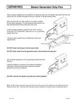
WARNING: Directly plumbing a drain line to the tempering tank
may cause personal injury or damage to the appliance. Not using
the supplied drain adapter will void your warranty.
If this equipment is being installed over an open floor drain, the
Drain Adapter is not required.
CAUTION: PVC OR CPVC are not acceptable materials for drains.
INSTALLING THE DRAIN ADAPTER
From the rear of the unit, position the drain adapter hooks through the slots in the floor of the
cabinet to and align with the holes at the rear and fasten in place with provided screws.
When making the drain connection to the 1½” NPT male thread of the drain adapter, use a pipe
wrench to firmly support the drain adapter nipple to prevent damage to the assembly.
WATER CONDITIONING:
Untreated water contains scale producing minerals which can precipitate onto the surfaces in
the steam generator. Due to the temperatures in the steam generator, the minerals can bake
onto the surfaces and components. This can result in early component failure and reduced
product life. Water level probes become coated with scale. Scale may bridge across the probe
insulator from the metal extension which senses the water level in the steam generator shell.
Once this scale becomes wet, the water level control is unable to maintain the proper water
level in the steam generator.
Part No. 10307R1 11 2020-02-26

INSTALLATION, OPERATION MANUAL, MODEL ETP-10G
3.0 INSTALLATION (Continued)
IMPORTANT: This equipment is furnished with Middleby TruH20 water
filtration system. An initial flushing procedure for the system must be
performed before using this equipment. (See page 31.)
CARTRIDGE SYSTEM INSTALLATION SET-UP
1. Unscrew two wing nuts that hold head assembly bracket until end of studs (See p. 30).
2. Tilt the bracket with head assembly towards outside of cabinet (See p. 30).
3. Push the M-C 10 (Stage 1) cartridge up into left side of head assembly until it stops and turn
to right until it stops in the Lock position. (Figure 1)
4. Push the M-S (Stage 2) cartridge up into right side of head assembly until it stops and turn
right until it stops in the Lock position. (Figure 2)
5. Tilt the bracket with assembly back in the cabinet. Hand tighten the wing nuts.
The cartridges should be replaced every six months or more often if the needle on the flow
gauge enters the red area (below 10 PSI). (See Cartridge Change Procedure, page 30).
Cartridge life depends greatly upon the quality of water.
For replacement cartridges call 480-591-4073.
FIGURE 1 FIGURE 2
Part No. 10307R1 12 2020-02-26

INSTALLATION, OPERATION MANUAL, MODEL ETP-10G
4.0 PERFORMANCE CHECK
WARNING: The steamer and its parts are hot. Use care when
operating, cleaning or servicing the steamer. The cooking
compartment contains live steam. Stay clear while opening door.
Once the steamer is installed and all mechanical connections have been made, thoroughly test
the steamer before operation.
1. Check that proper water, drain and electrical and gas connections have been made.
2. Turn main power switch “ON”. After approximately 10 minutes, the “READY” light should
come on and should remain on, indicating that the water temperature is approximately 200E
Fahrenheit (93E Celsius).
3. Check that “IGNITION” light comes on when the burner pilot is ON.
4. When the “READY” light comes on, set timer to the “5 minute” position. With door open,
observe that no steam is entering the compartment and that the “COOKING” light is OFF.
5. Close compartment door. The “COOKING” light should now be illuminated and steam
should be heard entering the compartment after about 45 seconds.
6. The tempering tank does not discharge to drain until the water in the top of the tank reaches
130EF or the unit is shut off and the generators are allowed to drain.
7. Open compartment door and observe that steam supply to chamber is cut off and the
“COOKING” light goes “OFF”.
8. Close compartment door and let cooking cycle finish. When the timer returns to “0" position,
a buzzer will sound signaling the end of the cooking cycle. Buzzer must be manually turned
off by setting the timer to its “OFF” position.
9. Complete the above steps for each cooking compartment.
10. To shut the steamer down, turn the main power switches to OFF and leave the compartment
doors slightly open to allow the inside to dry out.
Part No. 10307R1 13 2020-02-26

INSTALLATION, OPERATION MANUAL, MODEL ETP-10G
4.0 PERFORMANCE CHECK (Continued)
BEFORE FIRST USE
Clean the protective oils from all surfaces of the steamer. Use a non-corrosive, grease
dissolving commercial cleaner, following manufacturer’s directions. Rinse thoroughly and wipe
dry with soft clean cloth.
Part No. 10307R1 14 2020-02-26

INSTALLATION, OPERATION MANUAL, MODEL ETP-10G
5.0 OPERATION INSTRUCTIONS
WARNING: In the event of main burner ignition failure, a 5 minute
purge period must be observed prior to re-establishing ignition
source. If so equipped, some units will automatically re-attempt
ignition.
WARNING: In the event a gas odor is detected, shut down
equipment at the main shut off valve and contact the local gas
company or gas supplier for service.
LIGHTING
1. Ensure power, gas and water supply is on.
2. Turn power switch “ON”.
3. Generator tank will begin filling with water.
4. Once water level has been reached, the ignition light will come on and remain on throughout
the operation of the appliance.
5. When the “READY” light comes on the steamer is ready for use.
COOKING
CAUTION: Live steam and accumulated hot water in the
compartment may be released when the door is opened.
Before loading the steamer, be sure the ready light is on.
1. Slide pans of food into cooking compartment pan supports.
2. Close cooking compartment door.
3. Set timer cooking time:
a. 60-MINUTE TIMER - for timed cooking. Set timer to the required cooking time. (See
Cooking Guide on page 21).
b. HOLD - for holding cooked foods in a warm state. Will maintain the cooking
cavity at or above 150EF (65EC).
Part No. 10307R1 15 2020-02-26

INSTALLATION, OPERATION MANUAL, MODEL ETP-10G
5.0 OPERATION INSTRUCTIONS (Continued)
4. The cooking cycle may be interrupted at any time by opening the compartment door. To
resume operation, close the door.
5. Turn off buzzer, which sounds to indicate cooking is complete, by setting timer dial to the
OFF position.
6. Open door slightly at first letting most of the steam out of the compartment and then fully
open the door.
7. Unload by sliding pans of food from pan supports.
CAUTION: An obstructed drain can cause personal injury or
property damage.
Frequently check that the compartment drain and plumbing is free of all obstructions. Never
place food containers, food or food portion bags in the cooking compartment in such a way that
the compartment drain becomes obstructed.
Each compartment is equipped with a removable drain screen. Frequently check the drain
screen for accumulation of food particles. Should food particles accumulate against, or clog the
drain screen, remove it, clean it thoroughly and then replace it in its original position.
SHUTDOWN PROCEDURE
STAND BY
1. Set timer to “OFF” position and leave door slightly open.
END OF THE DAY
1. Set timer to “OFF”
2. Set power switches to “OFF”. Generators will drain automatically.
3. Leave doors ajar.
COMPLETE SHUTDOWN
1. Set timers to “OFF” and turn power switches “OFF”. Steam generators will drain
automatically.
2. Turn water supply “OFF”.
Part No. 10307R1 16 2020-02-26

INSTALLATION, OPERATION MANUAL, MODEL ETP-10G
5.0 OPERATION INSTRUCTIONS (Continued)
3. Close manual gas shut off valve.
4. Disconnect power supply.
WARNING: When this appliance is installed with casters and is
connected to the supply piping by means of a connector for
moveable appliances, a restraint to prevent damage to the
connector or quick disconnect device should have been installed. If
disconnection of the restraint is necessary, reconnect this restraint
after the appliance has been returned to its originally installed
position.
CAUTION: When the unit is not in use, leave the cooking
compartment doors ajar to prolong the life of the door gasket.
CLEANING
After each period of daily operation (more frequently as required to maintain cleanliness), the
steamer should be thoroughly cleaned by completing the following steps:
1. Remove left and right side pan supports by lifting up and off mounting studs. Remove the
drain screen in the rear of the compartment. Wash with a mild detergent. Rinse and set
aside for reassembly.
2. Wash cooking compartment interior using a mild detergent and water. Rinse and dry
thoroughly.
3. Replace pan supports and drain screen in compartment and leave door open.
DRAINAGE
Cooking Compartment Drainage
The bottom of the cooking compartment is angled slightly toward the rear of the unit. This
assures that any condensate build-up or spills will be directed toward the drain, which is located
at the rear bottom centre of the cooking compartment. Any liquid exiting the cooking
compartment runs down the cooking compartment drain tube and into the condensate
tempering tank.
Part No. 10307R1 17 2020-02-26

INSTALLATION, OPERATION MANUAL, MODEL ETP-10G
5.0 OPERATION INSTRUCTIONS (Continued)
Drip/Spill Trough Drainage
The Pressureless Steam Cooker has a drip/spill trough below the cooking compartment door. It
will catch any condensate gathering on the front of the unit when the door is opened.
WARNING: The steamer and its parts are hot. Use care when
operating, cleaning or servicing the steamer. The cooking
compartment contains live steam. Stay clear when opening door.
CAUTION: An obstructed drain can cause personal injury or
property damage.
CONTROLS
1. Ignition Light When lit, indicates that pilot burner has been
ignited.
2. Ready Pilot Light When lit, indicates steam generator has reached
200º Fahrenheit (93º Celsius) and is ready for the
cooking cycle.
3. Cooking Pilot Light When lit, indicates that a cooking cycle is in progress.
4. Timed Cooking/Hold Mode Set the cooking time (0 to 60 minutes) - steam
cooking will begin after the door is closed. The
cooking cycle will be interrupted if the door is opened
during the cooking cycle; resume cooking by closing
the door. Hold - For keeping cooked foods warm after
cooking, at or above 150EF (65E C).
5. Main Power Switch: ON The steam generator will automatically fill and begin
heating to the pre-set temperature for standby.
Red light will ignite on the main power switch.
5. Main Power Switch: OFF The steam generator will drain. No lights.
5. Main Power Switch: DELIME Closes the drain valve while TOTAL CONCEPT
liquid is being poured into the steam generator
during the Delime procedure. Amber light will ignite
on the main power switch.
6. Temperature Display Shows temperature within the cooking cavity.
7. Buzzer Signals end of cooking period (not shown).
Part No. 10307R1 18 2020-02-26

INSTALLATION, OPERATION MANUAL, MODEL ETP-10G
5.0 OPERATION INSTRUCTIONS (Continued)
CAUTION: Live steam and accumulated hot water in the
compartment may be released when the door is opened.
ADJUSTMENT FOR HIGH ALTITUDE LOCATIONS
Your steamer has been factory set when “ON” to maintain water temperature during the
“READY” phase at approximately 200E Fahrenheit (93E Celsius) just below water boiling point.
If the steamer is used at higher elevations (above 2000 feet), a qualified technician should
adjust the “READY” phase temperature down to an appropriate temperature, below the boiling
point of water.
TEST KITCHEN BULLETIN
Pressureless Cooker - Facts On Parade
1. Frozen vegetables should always be cooked in perforated 12" x 20" x 2 ½ “ (1/1 65 mm)
pans 7 ½ lbs. (34 kg) maximum per pan.
2. Frozen entrees should be underlined with a perforated pan for best results. If they are
defrosted first, the heating time will be decreased.
3. Fresh foods may also be cooked in this unit. Vegetables and other foods where the stock is
not to be retained should be cooked in perforated 12" x 20" x 2 ½" (1/1 65 mm) pans for the
most nutritious results.
4. There is a safety microswitch on the door which shuts off the steam each time the door is
opened if the unit is in the cooking cycle.
5. Total cooking time will vary depending on the load, even though the timer setting is the same.
6. All foods, except cakes and pastry, can be cooked in a steam cooking unit.
7. Steam cooked meals have greater nutritional value since they retain most of their vitamins
and minerals.
8. Because foods are cooked faster by the higher temperatures of steam cooking, they can be
prepared closer to serving time, insuring maximum freshness.
9. Steam cooked foods have a higher percent yield more portions per dollar spent.
Part No. 10307R1 19 2020-02-26

INSTALLATION, OPERATION MANUAL, MODEL ETP-10G
5.0 OPERATION INSTRUCTIONS (Continued)
10. Food may be served from the same pan in which it is steam cooked, thus reducing food
breakage since there is no extra handling or transferring of food from cooking pans to
serving pans. It also reduces pot washing tasks.
11. Some important advantages of steam cooking are labor saving, reduced operating costs,
space saving, and the lifting of heavy stock pots is eliminated.
12. Rice and spaghetti products, if thoroughly wet at the start of the cooking process, are very
easily prepared.
13. Food such as potatoes, poultry, seafood, and some meats may be blanched in the steam
cooker, thus reducing the total cooking time and grease absorption.
14. The steam cooker will loosen foods burned on pans making washing easier.
15. Solid pans are recommended when liquid is to be retained and perforated pans when the
liquid is not to be retained.
16. Eggs may be cooked out of the shell if they are to be chopped which eliminates peeling after
steaming.
17. The steam cooker can be opened during the cooking period to add or remove items.
Part No. 10307R1 20 2020-02-26
/