
16-Channel Premium Analog Mixer
with FireWire
48V 48V 48V 48V 48V 48V 48V 48V 48V 48V 48V 48V 48V 48V 48V 48V
SOLO
MUTE
SOLO
MUTE
SOLO
MUTE
SOLO
MUTE
SOLO
MUTE
SOLO
MUTE
SOLO
MUTE
SOLO
MUTE
SOLO
MUTE
SOLO
MUTE
SOLO
MUTE
SOLO
MUTE
SOLO
MUTE
SOLO
MUTE
SOLO
MUTE
SOLO
MUTE
EQ EQ EQ EQ EQ EQ EQ EQ EQ EQ EQ EQ EQ EQ EQ EQ
SOLO
SOLO
SOLO
SOLO
SOLO
SOLO
PREMIUM ANALOG MIXER
w/ PERKINS EQ & FIREWIRE
SUB
ASSIGN
MAIN
MIX
1
-
2
3
-
4
dB
30
20
10
40
50
5
5
U
60
10
OO
5
GAIN
CR/PHONES
ONLY
SUBS
1-2
3-4
SEND
TO
4
CONTROL
ROOM
PHONES
MAIN MIX
L
R
SUB ASSIGN
MAIN MIX
L
R
MAIN MIX
L
R
MAIN MIX
L
R
TO AUX 5
MAIN
SUBS
TO AUX 6
SENDS RETURNS
PRE
POST
PRE
POST
PRE
POST
PRE
POST
PRE
POST
PRE
POST
EFX TO
MON
RUDE
SOLO
20
15
10
6
3
0
2
4
7
10
20
30
SUB 3
-
4
FW 1-2
SUB 1
-
2
TAPE
ASSIGN TO
MAIN MIX
MAIN MIX
LEVEL
SET
CLIP
12345678910111213141516
12345678910111213141516
MAIN
MIX
SUB1 SUB4SUB3SUB2
SUB1 SUB4SUB3SUB2
4
3
22
11
6
4
2
1
5
6
3
PAN
AUX
AUX AUX AUX AUX AUX AUX AUX AUX AUX AUX AUX AUX AUX AUX AUX
12V 0.5A
LAMP
CTRL ROOM/PHONES
SOURCE
ASSIGN TO
FW 15-16
LEVEL
MIC
EXTERNAL
MIC
LINE
FW 1
LINE
FW 2
LINE
FW 16
LINE
FW 15
LINE
FW 14
LINE
FW 13
LINE
FW 12
LINE
FW 11
LINE
FW 10
LINE
FW 9
LINE
FW 8
LINE
FW 7
LINE
FW 6
LINE
FW 5
LINE
FW 4
75Hz
18dB/OCT
75Hz
18dB/OCT
75Hz
18dB/OCT
75Hz
18dB/OCT
75Hz
18dB/OCT
75Hz
18dB/OCT
75Hz
18dB/OCT
75Hz
18dB/OCT
75Hz
18dB/OCT
75Hz
18dB/OCT
75Hz
18dB/OCT
75Hz
18dB/OCT
75Hz
18dB/OCT
75Hz
18dB/OCT
LINE
FW 3
DESTINATION
AUX MASTER
SENDS 1-6
TO FW 9-14
TALKBACK
PHONES
AUX 1-6
12345678910111213141516
HIGH
12kHz
LOW
80Hz
U
+15-15
U
+15-15
U
+15-15
U
+15-15
8k400
2k
2k10 0
400
HIGH
MID
FREQ
LOW
MID
FREQ
+40dB
U
-20dB
U
20
30
40
60
L
R
MAX
OO
MAX
OO
MAX
OO
MAX
OO
+15
OO
+15
OO
+15
OO
+10
OO
+10
OO
+10
OO
+10
OO
+10
OO
+10
OO
+15
OO
+15
OO
+15
OO
MAX
OO
MAX
OO
MAX
OO
MAX
OO
MAX
OO
SEND
PRE
POST
OL
+10
0
-20
SUB
ASSIGN
MAIN
MIX
1
-
2
3
-
4
GAIN
4
2
1
5
6
3
PAN
HIGH
12kHz
LOW
80Hz
U
+15-15
U
+15-15
U
+15-15
U
+15-15
8k400
2k
2k10 0
400
HIGH
MID
FREQ
LOW
MID
FREQ
+40dB
U
-20dB
U
20
30
40
60
L
R
MAX
OO
MAX
OO
MAX
OO
MAX
OO
MAX
OO
MAX
OO
SEND
PRE
POST
OL
+10
0
-20
SUBS 1-4
TO FW 5-8
SOLO
LEVEL
PFL
AFL
TAPE TO
MAIN MIX
TAPE IN
MAX
OO
MAX
OO
SOLO
MODE
LR
0dB=0dBu
POWER
SUB
ASSIGN
MAIN
MIX
1
-
2
3
-
4
GAIN
4
2
1
5
6
3
PAN
HIGH
12kHz
LOW
80Hz
U
+15-15
U
+15-15
U
+15-15
U
+15-15
8k400
2k
2k10 0
400
HIGH
MID
FREQ
LOW
MID
FREQ
+40dB
U
-20dB
U
20
30
40
60
L
R
MAX
OO
MAX
OO
MAX
OO
MAX
OO
MAX
OO
MAX
OO
SEND
PRE
POST
OL
+10
0
-20
SUB
ASSIGN
MAIN
MIX
1
-
2
3
-
4
GAIN
4
2
1
5
6
3
PAN
HIGH
12kHz
LOW
80Hz
U
+15-15
U
+15-15
U
+15-15
U
+15-15
8k400
2k
2k10 0
400
HIGH
MID
FREQ
LOW
MID
FREQ
+40dB
U
-20dB
U
20
30
40
60
L
R
MAX
OO
MAX
OO
MAX
OO
MAX
OO
MAX
OO
MAX
OO
SEND
PRE
POST
OL
+10
0
-20
SUB
ASSIGN
MAIN
MIX
1
-
2
3
-
4
GAIN
4
2
1
5
6
3
PAN
HIGH
12kHz
LOW
80Hz
U
+15-15
U
+15-15
U
+15-15
U
+15-15
8k400
2k
2k10 0
400
HIGH
MID
FREQ
LOW
MID
FREQ
+40dB
U
-20dB
U
20
30
40
60
L
R
MAX
OO
MAX
OO
MAX
OO
MAX
OO
MAX
OO
MAX
OO
SEND
PRE
POST
OL
+10
0
-20
SUB
ASSIGN
MAIN
MIX
1
-
2
3
-
4
GAIN
4
2
1
5
6
3
PAN
HIGH
12kHz
LOW
80Hz
U
+15-15
U
+15-15
U
+15-15
U
+15-15
8k400
2k
2k10 0
400
HIGH
MID
FREQ
LOW
MID
FREQ
+40dB
U
-20dB
U
20
30
40
60
L
R
MAX
OO
MAX
OO
MAX
OO
MAX
OO
MAX
OO
MAX
OO
SEND
PRE
POST
OL
+10
0
-20
SUB
ASSIGN
MAIN
MIX
1
-
2
3
-
4
GAIN
4
2
1
5
6
3
PAN
HIGH
12kHz
LOW
80Hz
U
+15-15
U
+15-15
U
+15-15
U
+15-15
8k400
2k
2k10 0
400
HIGH
MID
FREQ
LOW
MID
FREQ
+40dB
U
-20dB
U
20
30
40
60
L
R
MAX
OO
MAX
OO
MAX
OO
MAX
OO
MAX
OO
MAX
OO
SEND
PRE
POST
OL
+10
0
-20
SUB
ASSIGN
MAIN
MIX
1
-
2
3
-
4
GAIN
4
2
1
5
6
3
PAN
HIGH
12kHz
LOW
80Hz
U
+15-15
U
+15-15
U
+15-15
U
+15-15
8k400
2k
2k10 0
400
HIGH
MID
FREQ
LOW
MID
FREQ
+40dB
U
-20dB
U
20
30
40
60
L
R
MAX
OO
MAX
OO
MAX
OO
MAX
OO
MAX
OO
MAX
OO
SEND
PRE
POST
OL
+10
0
-20
SUB
ASSIGN
MAIN
MIX
1
-
2
3
-
4
GAIN
4
2
1
5
6
3
PAN
HIGH
12kHz
LOW
80Hz
U
+15-15
U
+15-15
U
+15-15
U
+15-15
8k400
2k
2k10 0
400
HIGH
MID
FREQ
LOW
MID
FREQ
+40dB
U
-20dB
U
20
30
40
60
L
R
MAX
OO
MAX
OO
MAX
OO
MAX
OO
MAX
OO
MAX
OO
SEND
PRE
POST
OL
+10
0
-20
SUB
ASSIGN
MAIN
MIX
1
-
2
3
-
4
GAIN
4
2
1
5
6
3
PAN
HIGH
12kHz
LOW
80Hz
U
+15-15
U
+15-15
U
+15-15
U
+15-15
8k400
2k
2k10 0
400
HIGH
MID
FREQ
LOW
MID
FREQ
+40dB
U
-20dB
U
20
30
40
60
L
R
MAX
OO
MAX
OO
MAX
OO
MAX
OO
MAX
OO
MAX
OO
SEND
PRE
POST
OL
+10
0
-20
SUB
ASSIGN
MAIN
MIX
1
-
2
3
-
4
GAIN
4
2
1
5
6
3
PAN
HIGH
12kHz
LOW
80Hz
U
+15-15
U
+15-15
U
+15-15
U
+15-15
8k400
2k
2k10 0
400
HIGH
MID
FREQ
LOW
MID
FREQ
+40dB
U
-20dB
U
20
30
40
60
L
R
MAX
OO
MAX
OO
MAX
OO
MAX
OO
MAX
OO
MAX
OO
SEND
PRE
POST
OL
+10
0
-20
SUB
ASSIGN
MAIN
MIX
1
-
2
3
-
4
GAIN
4
2
1
5
6
3
PAN
HIGH
12kHz
LOW
80Hz
U
+15-15
U
+15-15
U
+15-15
U
+15-15
8k400
2k
2k10 0
400
HIGH
MID
FREQ
LOW
MID
FREQ
+40dB
U
-20dB
U
20
30
40
60
L
R
MAX
OO
MAX
OO
MAX
OO
MAX
OO
MAX
OO
MAX
OO
SEND
PRE
POST
OL
+10
0
-20
SUB
ASSIGN
MAIN
MIX
1
-
2
3
-
4
GAIN
4
2
1
5
6
3
PAN
HIGH
12kHz
LOW
80Hz
U
+15-15
U
+15-15
U
+15-15
U
+15-15
8k400
2k
2k10 0
400
HIGH
MID
FREQ
LOW
MID
FREQ
+40dB
U
-20dB
U
20
30
40
60
L
R
MAX
OO
MAX
OO
MAX
OO
MAX
OO
MAX
OO
MAX
OO
SEND
PRE
POST
OL
+10
0
-20
SUB
ASSIGN
MAIN
MIX
1
-
2
3
-
4
GAIN
4
2
1
5
6
3
PAN
HIGH
12kHz
LOW
80Hz
U
+15-15
U
+15-15
U
+15-15
U
+15-15
8k400
2k
2k10 0
400
HIGH
MID
FREQ
LOW
MID
FREQ
+40dB
U
-20dB
U
20
30
40
60
L
R
MAX
OO
MAX
OO
MAX
OO
MAX
OO
MAX
OO
MAX
OO
SEND
PRE
POST
OL
+10
0
-20
SUB
ASSIGN
MAIN
MIX
1
-
2
3
-
4
GAIN
4
2
1
5
6
3
PAN
HIGH
12kHz
LOW
80Hz
U
+15-15
U
+15-15
U
+15-15
U
+15-15
8k400
2k
2k10 0
400
HIGH
MID
FREQ
LOW
MID
FREQ
+40dB
U
-20dB
U
20
30
40
60
L
R
MAX
OO
MAX
OO
MAX
OO
MAX
OO
MAX
OO
MAX
OO
SEND
PRE
POST
OL
+10
0
-20
SUB
ASSIGN
MAIN
MIX
1
-
2
3
-
4
GAIN
4
2
1
5
6
33
PAN
HIGH
12kHz
LOW
80Hz
U
+15-15
U
+15-15
U
+15-15
U
+15-15
8k400
2k
2k10 0
400
HIGH
MID
FREQ
LOW
MID
FREQ
+40dB
U
-20dB
U
20
30
40
60
L
R
MAX
OO
MAX
OO
MAX
OO
MAX
OO
MAX
OO
MAX
OO
SEND
PRE
POST
OUT
IN
OUT
IN
OUT
IN
OUT
IN
OUT
IN
OUT
IN
OUT
IN
OUT
IN
OUT
IN
OUT
IN
OUT
IN
OUT
IN
OUT
IN
OUT
IN
OUT
IN
OUT
IN
OL
+10
0
-20
AUX MASTERS
R123 123456L4
MAIN MIX
ALTERNATE FIREWIRE ASSIGNMENTS
SUBGROUPS
OWNER'S MANUAL

2 Onyx 1640i
1. Read these instructions.
2. Keep these instructions.
3. Heed all warnings.
4. Follow all instructions.
5. Do not use this apparatus near water.
6. Clean only with a dry cloth.
7. Do not block any ventilation openings. Install in accordance with the
manufacturer’s instructions.
8. Do not install near any heat sources such as radiators, heat registers,
stoves, or other apparatus (including amplifi ers) that produce heat.
9. Do not defeat the safety purpose of the polarized or grounding-type
plug. A polarized plug has two blades with one wider than the other.
A grounding-type plug has two blades and a third grounding prong.
The wide blade or the third prong are provided for your safety. If the
provided plug does not fi t into your outlet, consult an electrician for
replacement of the obsolete outlet.
10.
Do not overload wall outlets and extension cords as this can result in a
risk of fi re or electric shock.
11.
Protect the power cord from being walked on or pinched particularly at
plugs, convenience receptacles, and the point where they exit from the
apparatus.
12.
Only use attachments/accessories specifi ed by the manufacturer.
13.
Use only with a cart, stand, tripod, bracket, or
table specifi ed by the manufacturer, or sold with
the apparatus. When a cart is used, use caution
when moving the cart/apparatus combination to
avoid injury from tip-over.
14.
Unplug this apparatus during lightning storms or
when unused for long periods of time.
15.
Refer all servicing to qualifi ed service personnel. Servicing is required
when the apparatus has been damaged in any way, such as power-
supply cord or plug is damaged, liquid has been spilled or objects have
fallen into the apparatus, the apparatus has been exposed to rain or
moisture, does not operate normally, or has been dropped.
16.
This apparatus shall not be exposed to dripping or splashing, and no
object fi lled with liquids, such as vases or beer glasses, shall be placed
on the apparatus.
17.
This apparatus has been designed with Class-I construction and must
be connected to a mains socket outlet with a protective earthing con-
nection (the third grounding prong).
18.
This apparatus has been equipped with a rocker-style AC mains power
switch. This switch is located on the rear panel and should remain
readily accessible to the user.
19.
The MAINS plug or an appliance coupler is used as the disconnect
device, so the disconnect device shall remain readily operable.
20. NOTE: This equipment has been tested and found to comply with
the limits for a Class B digital device, pursuant to part 15 of the FCC
Rules. These limits are designed to provide reasonable protection
against harmful interference in a residential installation. This equip-
ment generates, uses, and can radiate radio frequency energy and, if
not installed and used in accordance with the instructions, may cause
harmful interference to radio communications. However, there is no
guarantee that interference will not occur in a particular installation. If
this equipment does cause harmful interference to radio or television
reception, which can be determined by turning the equipment off and
on, the user is encouraged to try to correct the interference by one or
more of the following measures:
• Reorient or relocate the receiving antenna.
• Increase the separation between the equipment and the
receiver.
• Connect the equipment into an outlet on a circuit different from
that to which the receiver is connected.
• Consult the dealer or an experienced radio/TV technician for
help.
CAUTION: Changes or modifi cations to this device not expressly
approved by LOUD Technologies Inc. could void the user's authority to
operate the equipment under FCC rules.
21.
This apparatus does not exceed the Class A/Class B (whichever is
applicable)
limits for radio noise emissions from digital apparatus as
set out in the radio interference regulations of the Canadian Department
of Com mu ni ca tions.
ATTENTION — Le présent appareil numérique n’émet pas de bruits
radioélectriques dépassant las limites applicables aux appareils
numériques de class A/de class B (selon le cas) prescrites dans le
réglement sur le brouillage radioélectrique édicté par les ministere des
com mu ni ca tions du Canada.
22.
Exposure to extremely high noise levels may cause permanent hearing
loss. Individuals vary considerably in susceptibility to noise-induced
hearing loss, but nearly everyone will lose some hearing if exposed to
suffi ciently intense noise for a period of time. The U.S. Government’s
Occupational Safety and Health Administration (OSHA) has specifi ed
the permissible noise level exposures shown in the following chart.
According to OSHA, any exposure in excess of these permissible limits
could result in some hearing loss. To ensure against potentially danger-
ous exposure to high sound pressure levels, it is recommended that all
persons exposed to equipment capable of producing high sound pres-
sure levels use hearing protectors while the equipment is in operation.
Ear plugs or protectors in the ear canals or over the ears must be worn
when operating the equipment in order to prevent permanent hearing
loss if exposure is in excess of the limits set forth here:
Important Safety Instructions
PORTABLE CART
WARNING
CAUTION AVIS
RISK OF ELECTRIC SHOCK. DO NOT OPEN
RISQUE DE CHOC ELECTRIQUE. NE PAS OUVRIR
CAUTION: TO REDUCE THE RISK OF ELECTRIC SHOCK DO NOT REMOVE COVER (OR BACK)
NO USER-SERVICEABLE PARTS INSIDE. REFER SERVICING TO QUALIFIED PERSONNEL
ATTENTION: POUR EVITER LES RISQUES DE CHOC ELECTRIQUE, NE PAS ENLEVER LE COUVERCLE.
AUCUN ENTRETIEN DE PIECES INTERIEURES PAR L'USAGER.
CONFIER L'ENTRETIEN AU PERSONNEL QUALIFIE.
AVIS: POUR EVITER LES RISQUES D'INCENDIE OU D'ELECTROCUTION, N'EXPOSEZ PAS CET ARTICLE
A LA PLUIE OU A L'HUMIDITE
The lightning flash with arrowhead symbol within an equilateral triangle is
intended to alert the user to the presence of uninsulated "dangerous
voltage" within the product's enclosure, that may be of sufficient magnitude
to constitute a risk of electric shock to persons.
Le symbole éclair avec point de flèche à l'intérieur d'un triangle équilatéral
est utilisé pour alerter l'utilisateur de la présence à l'intérieur du coffret de
"voltage dangereux" non isolé d'ampleur suffisante pour constituer un risque
d'éléctrocution.
The exclamation point within an equilateral triangle is intended to alert the
user of the presence of important operating and maintenance (servicing)
instructions in the literature accompanying the appliance.
Le point d'exclamation à l'intérieur d'un triangle équilatéral est employé
pour alerter les utilisateurs de la présence d'instructions importantes pour le
fonctionnement et l'entretien (service) dans le livret d'instruction
accompagnant l'appareil.
WARNING — To reduce the risk of fi re or electric shock, do not
expose this apparatus to rain or moisture.
Duration,
per day in
hours
Sound Level
dBA, Slow
Response
Typical Example
8 90 Duo in small club
692
4 95 Subway Train
397
2 100 Very loud classical music
1.5 102
1 105 Anita and Woody screaming at Troy
about deadlines
0.5 110
0.25 or less 115 Loudest parts at a rock concert
Correct disposal of this product. This symbol indicates that this product should not be disposed of with your household waste, according to the WEEE Directive (2002/96/EC) and your national law. This product
should be handed over to an authorized collection site for recycling waste electrical and electronic equipment (EEE). Improper handling of this type of waste could have a possible negative impact on the environment and
human health due to potentially hazardous substances that are generally associated with EEE. At the same time, your cooperation in the correct disposal of this product will contribute to the effective usage of natural
resources. For more information about where you can drop off your waste equipment for recycling, please contact your local city offi ce, waste authority, or your household waste disposal service.

Owner's Manual 3
Part No. SW0724 Rev. B 02.2010
©2010 LOUD Technologies Inc. All Rights Reserved.
Loosely based on a dream sequence in which the technical writer is given keys to a
sports car of his choice, unlimited gas, and closed roads. The dream suddenly ends and
reality kicks in. A mixer manual to write, a mixer manual to write!
Set the levels
It’s not even necessary to hear what you’re doing to
set optimal levels. But if you’d like to: Plug headphones
into the phones output jack, then turn up the phones
knob just a little.
1. Turn on the mixer by pressing the top edge of
the power switch.
2. For one channel, press the solo switch in, and
the rude solo light will turn on.
3. Play something into that input at real-world
levels.
4. Adjust that channel's gain control until the
right main meter stays around the 0 dB LED
(marked "level set").
5. Disengage the channel's solo switch.
6. Repeat steps 2 to 5 for the remaining channels.
7. Turn up the channel level to the "U" mark.
8. Slowly turn up the main mix level until you
hear the signals in your speakers.
9. If needed, apply some channel EQ wisely.
10. Adjust the channel levels to get the best mix.
Keep the gain controls and levels fully down on
unused channels.
11. During the performance, if you notice a channel
OL LED turning on during peaks, carefully turn
down that channel's gain control until OL does
not turn on.
FireWire
• See page 42 for details of getting started with
FireWire.
• PC drivers are on the supplied CD-ROM. Mac
OS X contains built-in drivers, so no software
installation is required.
Other Notes
• When shutting down, turn off any power
amplifi ers or powered speakers fi rst. When
powering up, turn them on last. This will
reduce the chance of turn-on or turn-off
thumps.
• Always turn down the phones level when
making connections, pressing solo, or doing
anything that may cause loudness in the
headphones. This will help protect your
hearing.
• Always turn down the main mix level and
control room level when making connections to
the mixer. Better yet, turn off the power.
• Save the shipping box!
Quick Start
We realize that you must be really keen
to try out your new mixer. Please read the
safety instructions on page 2, then have
a look through some of the features and
details in this manual.
Setup
Use the mixer in a nice clean and dry environment,
free from dryer lint and dust bunnies.
Zero the controls
1. Fully turn down all the knobs to minimum,
except for the channel EQ and pan controls,
which should be centered.
2. Make sure all buttons are in the out position.
Connections
1. Make sure the AC power switch is off before
making any connections.
2. Push the linecord securely into the IEC
connector on the rear panel, and plug it into a
3-prong AC outlet. The mixer can accept
any
AC voltage ranging from 100 VAC to 240 VAC.
3. Plug a balanced microphone into one of the mic
XLR (3-pin) connectors. Or connect any
line-level signal (keyboard, or guitar preamp)
to a line input jack using a TS or a TRS 1/4"
plug.
4. If your microphone requires phantom power,
press in the 48V phantom power button.
5. You can connect a guitar directly to line inputs
1 or 2 without needing a DI box, if you fi rst
engage the hi-z switch on these channels.
6. All 16 channels have insert jacks that can be
used to connect an external effects or dynamics
processor into the signal chain.
7. Connect the main outputs of the mixer (either
XLR or TRS 1/4") to the line level inputs of your
amplifi er (with speakers already attached) or
to the line level inputs of powered speakers.

4 Onyx 1640i
Introduction
Thank you for choosing a Mackie Onyx 1640i
professional compact mixer. The Onyx-i series of mixers
offer built-in FireWire, along with the newest features
and latest technologies for live sound reinforcement
and analog or digital studio recording, all in a durable,
road-worthy package.
The Onyx 1640i is equipped with 16 of our premium
precision-engineered studio-grade Onyx mic preamps.
Mackie is renowned for the high-quality mic preamps
used in our mixers, and the Onyx mic pre’s are better
than ever, with specifi cations rivaling expensive
stand-alone mic preamplifi ers.
Channels 1 and 2 feature high-impedance
instrument/line-level inputs so you can connect an
acoustic, electric, or bass guitar directly into the mixer,
eliminating the need for an external direct box.
Features
• 16-channel premium analog mixer with
integrated 24-bit/96kHz FireWire I/O
• 16 Onyx boutique quality mic preamps
• 4-band Perkins EQ with sweepable mids on all
channels
• Full 16x16 FireWire channel streaming for
ultimate DAW integration
• Flexible FireWire routing, including aux sends,
groups and pre/post EQ assignment for all
channels
• 6 aux sends with pre/post assignment and solo
• Smooth 60mm channel and master faders
• Built-in DI on fi rst two channels for direct
connection of guitars, bass, etc.
• Individual 48V phantom power switches on all
mic inputs
• 4-segment metering on every channel
• 4-bus architecture for fl exible sub-grouping of
channels
• Talkback section for use with internal or
external mic
• Rotating I/O pod for desktop or rackmount
operation - rack ears included
• "Planet-Earth" switching power supply for
worldwide use
Deep FireWire Integration
The Onyx 1640i is the fl agship mixer of the series,
boasting a full 16x16 FireWire interface, allowing for
something that a DAW could never do alone: A true
tape-style mixdown.
If you are doing a real analog mixdown, you will
surely benefi t from the premium features that the 1640i
provides. Send all channels simultaneously to your DAW,
get them recorded and apply your plug-ins. Once you
have everything edited and ready, you can simply route
up to 16 streams straight back into the 1640i's channel
strips. You can choose to apply some of that lovely
Perkins EQ if you wish. All of these signals hit our
premium, high-headroom custom summing bus. It
combines the best of both the digital and analog realm
to create seamless workfl ow that makes your sessions
faster, easier and better sounding than ever possible
before.
Wet or Dry?
Every channel on the mixer can be routed pre or post
EQ to the computer, allowing you to choose whether to
implement 'EQ to tape' or not.
Studio Quality Effects
All aux sends are routable to the computer, allowing
you to utilize your computer as a powerful FX engine by
implementing your favorite plug-ins in a live scenario.
Preserve Your Mix
Master L/R is routable to the computer for recording
your analog mix. Burn and sell CDs of the mix at the end
of the gig!
Mix Integration
Up to 16 sources from your computer can be routed to
either the control room for instant monitoring or right
back into the channel strips for mix integration.
Latency-Free Overdubs
Having a "real" mixer has its benefi ts. Latency-free
overdubs are simple since you are using an analog
mixer. No more wasted time dealing with the
complicated "DSP" mixers commonly used on
standalone interfaces.
Most DAWs also support device aggregation, allowing
you to use multiple 1640i's in any given session. Imagine
32 or 48 channels, streaming effortlessly to and from
your DAW, with all the power right in your hands. It's
the ideal combination of modern technology and classic
mixing style.

Owner's Manual 5
How To Use This Manual
The fi rst pages after the table of contents are the
hookup diagrams. These show typical setups for fun
times with your mixer.
Next is a detailed tour of the entire mixer. The
descriptions are divided into sections, just as your mixer
is organized into distinct zones:
• Back panel / connections
• Channel controls
• Control room / phones source
• Aux master
• Talkback
• Main and subs mix
Throughout these sections you’ll fi nd illustrations
with each feature numbered and described in nearby
paragraphs.
This icon marks infor mation that is critically
important or unique to the mixer. For your own
good, read them and remember them.
This icon will lead you to some explanations of
features and practical tips. Go ahead and skip
these if you need to leave the room in a hurry.
Appendix A: Service information.
Appendix B: Connectors.
Appendix C: Technical information.
Appendix D: Rotopod instructions.
Appendix E: FireWire.
Appendix F: Modifi cations.
Need help with your new mixer?
• Visit www.mackie.com and click Sup-
port to fi nd: FAQs, manuals, addendums,
and other useful information.
• Email us at: [email protected]om.
• Telephone 1-800-898-3211 to speak with
one of our splendid technical support
chaps (Monday through Friday, normal
business hours, PST).

6 Onyx 1640i
Contents
IMPORTANT SAFETY INSTRUCTIONS ........................ 2
QUICK START .......................................................... 3
INTRODUCTION ...................................................... 4
YOU ARE HERE ....................................................... 6
HOOKUP DIAGRAMS............................................... 7
FEATURES ............................................................. 10
REAR PANEL / CONNECTION SECTION ................ 10
1. POWER CONNECTION ............................. 10
2. POWER SWITCH ..................................... 10
3. FIREWIRE CONNECTIONS ........................ 10
4. MIC INPUTS ........................................... 11
5. LINE INPUTS .......................................... 11
6. INSERT .................................................. 11
7. TALKBACK MIC ....................................... 12
8. LEFT/RIGHT XLR MAIN OUTPUTS ........... 12
9. MAIN OUTPUT LEVEL .............................. 12
10. LEFT/RIGHT 1/4" MAIN OUTPUTS .......... 12
11. MONO OUT............................................ 12
12. MONO OUT LEVEL CONTROL ................... 12
13. MAIN INSERTS ....................................... 12
14. TAPE INPUTS ......................................... 12
15. TAPE OUTPUTS ...................................... 12
16. CTRL-RM OUT ........................................ 13
17. SUB OUTS .............................................. 13
18. AUX RETURNS 1-4 ................................. 13
19. AUX SENDS 1-6 ..................................... 13
20. RECORDING OUTS .................................. 13
21. TURD POLISHER ..................................... 13
CHANNEL CONTROLS ......................................... 14
22. 48V PHANTOM POWER ......................... 14
23. LOW CUT ............................................... 14
24. INPUT (LINE OR FW 1-16) ...................... 15
25. HI-Z SWITCH (CHS. 1 AND 2 ONLY) ........ 15
26. GAIN CONTROL ...................................... 15
27. SEND FIREWIRE PRE/POST ..................... 15
28. EQ IN/OUT ............................................ 16
29. HIGH EQ ................................................ 16
30. HIGH-MID EQ FREQUENCY ...................... 16
31. HIGH MID EQ LEVEL ............................... 16
32. LOW-MID EQ FREQUENCY....................... 16
33. LOW MID EQ LEVEL ................................ 16
34. LOW EQ ................................................. 16
35. AUX SENDS 1-6 ..................................... 16
36. PAN....................................................... 17
37. MUTE .................................................... 17
38. CHANNEL FADER .................................... 17
39. -20, 0, +10 AND OL LEDS ........................ 17
40. ASSIGN ................................................... 17
41. SOLO ..................................................... 18
CONTROL ROOM/PHONES AND METERS ............ 19
42. HEADPHONE OUTPUT ............................ 19
43. LAMP ...................................................... 19
44. MAIN MIX .............................................. 19
45. TAPE, SUB 1-4, FW 1-2 ............................ 20
46. ASSIGN TO MAIN MIX ............................. 20
47. CONTROL ROOM KNOB ........................... 20
48. PHONES KNOB ........................................ 20
49. LEFT/RIGHT LEVEL METERS ...................... 20
50. RUDE SOLO LIGHT ................................... 21
51. SOLO LEVEL ............................................. 21
52. SOLO MODE ............................................ 21
53. TAPE IN ................................................... 21
54. TAPE TO MAIN MIX ................................. 21
AUX MASTER ..................................................... 22
55. MASTER AUX SENDS 1-6 ......................... 22
56. PRE/POST .............................................. 22
57. AUX SENDS SOLO .................................... 22
58. AUX SENDS 1-6 TO FW 9-14 ................... 23
59. MASTER AUX RETURNS 1-4 ..................... 23
60. EFX TO MON ........................................... 23
61. AUX RETURN 3 SEND TO MAIN/SUBS ...... 23
62. SUBS 1-2/3-4 ......................................... 23
63. AUX RETURN 4 TO CR/PHONES ONLY ...... 24
64. POWER LED ............................................. 24
TALKBACK ......................................................... 25
65. TALKBACK MIC ........................................ 25
66. TALKBACK LEVEL ..................................... 25
67. DESTINATION: PHONES, AUX 1-6 ............. 25
68. TALKBACK SWITCH .................................. 25
69. EXTERNAL MIC SWITCH ........................... 25
MAIN AND SUBS MIX ........................................ 26
70. SUB ASSIGN .......................................... 26
71. SUB 1-4 FADERS .................................... 26
72. SUBS 1-4 TO FW 5-8 .............................. 26
73. MAIN MIX ............................................. 27
74. ASSIGN TO FW 15-16 ............................ 27
APPENDIX A: SERVICE INFORMATION .................... 28
APPENDIX B: CONNECTIONS.................................. 29
APPENDIX C: TECHNICAL INFORMATION ................ 31
APPENDIX D: ROTOPOD INSTRUCTIONS ................ 34
APPENDIX E: FIREWIRE ......................................... 42
APPENDIX F: MODIFICATIONS ............................... 46
LIMITED WARRANTY ............................................. 49

Owner's Manual 7
Hookup Diagrams
Typical Live Sound System
This diagram shows an electric guitar connected to the channel 1 line input via an amp modeler, a bass
guitar connected directly to channel 2 (hi-z switch in), microphones connected to channel 3-8 mic inputs, and
a keyboard connected to the channel 9 and 10 inputs. An iPod
®
dock connects to the tape input. Headphones
are used to monitor levels.
A dynamics processor is connected to the insert jack of channel 2 to work its magic on your bass. Vocal
compressors are connected to the channel 7 and 8 inserts. A stereo compressor is connected to the main
inserts.
SRM450v2 powered speakers are used as stage monitors for the band; they are connected to the aux 1
send jack (in pre-fader mode). An SRM150 powered speaker receives a mono input from aux 2 send (in
pre-fader mode), and is used as a monitor for your keyboard player. A reverb processor receives a mono
input from aux 3 send (in post-fader mode), and its stereo outputs connect to the stereo aux 3 return inputs. A
delay processor receives a mono input from aux 4 send (in post-fader mode), and its stereo outputs connect
to the stereo aux 4 return inputs. The aux 5 and 6 sends are sent directly to the computer for processing by
whatever VST plug-ins you may desire. These are then returned for playback on channels 15/16.
The club is driven by connecting a pair of HD1801 powered subwoofers and a pair of HD1531 powered
speakers to the main left and right outputs. Recording outputs 1-16 may be used in lieu of a splitter. All inputs
fed into the monitor board may then be re-routed from these outputs into a separate front-of-house console.
A laptop connects to a FireWire port, allowing the 2-channel main mix, and individual channels to be
recorded. Any music (iTunes
®
, mp3s, or other pre-recorded audio) can be played back from the laptop. These
can enter as either a source for the control room and phones, or any available channels.
48V 48V 48V 48V 48V 48V 48V 48V 48V 48V 48V 48V 48V 48V 48V 48V
SOLO
MUTE
SOLO
MUTE
SOLO
MUTE
SOLO
MUTE
SOLO
MUTE
SOLO
MUTE
SOLO
MUTE
SOLO
MUTE
SOLO
MUTE
SOLO
MUTE
SOLO
MUTE
SOLO
MUTE
SOLO
MUTE
SOLO
MUTE
SOLO
MUTE
SOLO
MUTE
EQ EQ EQ EQ EQ EQ EQ EQ EQ EQ EQ EQ EQ EQ EQ EQ
SOLO
SOLO
SOLO
SOLO
SOLO
SOLO
PREMIUM ANALOG MIXER
w/ PERKINS EQ & FIREWIRE
SUB
ASSIGN
MAIN
MIX
1
-
2
3
-
4
dB
30
20
10
40
50
5
5
U
60
10
OO
5
GAIN
CR/PHONES
ONLY
SUBS
1-2
3-4
SEND
TO
4
CONTROL
ROOM
PHONES
MAIN MIX
L
R
SUB ASSIGN
MAIN MIX
L
R
MAIN MIX
L
R
MAIN MIX
L
R
TO AUX 5
MAIN
SUBS
TO AUX 6
SENDS RETURNS
PRE
POST
PRE
POST
PRE
POST
PRE
POST
PRE
POST
PRE
POST
EFX TO
MON
RUDE
SOLO
20
15
10
6
3
0
2
4
7
10
20
30
SUB 3
-
4
FW 1-2
SUB 1
-
2
TAP E
ASSIGN TO
MAIN MIX
MAIN MIX
LEVEL
SET
CLIP
1234 56 78910111213141516
1234 56 78910111213141516
MAIN
MIX
SUB1 SUB4SUB3SUB2
SUB1 SUB4SUB3SUB2
4
3
22
11
6
4
2
1
5
6
3
PAN
AUX
AUX AUX AUX AUX AUX AUX AUX AUX AUX AUX AUX AUX AUX AUX AUX
12V 0.5A
LAMP
CTRL ROOM/PHONES
SOURCE
ASSIGN TO
FW 15-16
LEVEL
MIC
EXTERNAL
MIC
LINE
FW 1
LINE
FW 2
LINE
FW 16
LINE
FW 15
LINE
FW 14
LINE
FW 13
LINE
FW 12
LINE
FW 11
LINE
FW 10
LINE
FW 9
LINE
FW 8
LINE
FW 7
LINE
FW 6
LINE
FW 5
LINE
FW 4
75Hz
18dB/OCT
75Hz
18dB/OCT
75Hz
18dB/OCT
75Hz
18dB/OCT
75Hz
18dB/OCT
75Hz
18dB/OCT
75Hz
18dB/OCT
75Hz
18dB/OCT
75Hz
18dB/OCT
75Hz
18dB/OCT
75Hz
18dB/OCT
75Hz
18dB/OCT
75Hz
18dB/OCT
75Hz
18dB/OCT
LINE
FW 3
DESTINATION
AUX MASTER
SENDS 1-6
TO FW 9-14
TALKBACK
PHONES
AUX 1-6
12345678910111213141516
HIGH
12kHz
LOW
80Hz
U
+15-15
U
+15-15
U
+15-15
U
+15-15
8k400
2k
2k10 0
400
HIGH
MID
FREQ
LOW
MID
FREQ
+40dB
U
-20dB
U
20
30
40
60
L
R
MAX
OO
MAX
OO
MAX
OO
MAX
OO
+15
OO
+15
OO
+15
OO
+10
OO
+10
OO
+10
OO
+10
OO
+10
OO
+10
OO
+15
OO
+15
OO
+15
OO
MAX
OO
MAX
OO
MAX
OO
MAX
OO
MAX
OO
SEND
PRE
POST
OL
+10
0
-20
SUB
ASSIGN
MAIN
MIX
1
-
2
3
-
4
GAIN
4
2
1
5
6
3
PAN
HIGH
12kHz
LOW
80Hz
U
+15-15
U
+15-15
U
+15-15
U
+15-15
8k400
2k
2k10 0
400
HIGH
MID
FREQ
LOW
MID
FREQ
+40dB
U
-20dB
U
20
30
40
60
L
R
MAX
OO
MAX
OO
MAX
OO
MAX
OO
MAX
OO
MAX
OO
SEND
PRE
POST
OL
+10
0
-20
SUBS 1-4
TO FW 5-8
SOLO
LEVEL
PFL
AFL
TAPE TO
MAIN MIX
TAPE IN
MAX
OO
MAX
OO
SOLO
MODE
LR
0dB=0dBu
POWER
SUB
ASSIGN
MAIN
MIX
1
-
2
3
-
4
GAIN
4
2
1
5
6
3
PAN
HIGH
12kHz
LOW
80Hz
U
+15-15
U
+15-15
U
+15-15
U
+15-15
8k400
2k
2k10 0
400
HIGH
MID
FREQ
LOW
MID
FREQ
+40dB
U
-20dB
U
20
30
40
60
L
R
MAX
OO
MAX
OO
MAX
OO
MAX
OO
MAX
OO
MAX
OO
SEND
PRE
POST
OL
+10
0
-20
SUB
ASSIGN
MAIN
MIX
1
-
2
3
-
4
GAIN
4
2
1
5
6
3
PAN
HIGH
12kHz
LOW
80Hz
U
+15-15
U
+15-15
U
+15-15
U
+15-15
8k400
2k
2k10 0
400
HIGH
MID
FREQ
LOW
MID
FREQ
+40dB
U
-20dB
U
20
30
40
60
L
R
MAX
OO
MAX
OO
MAX
OO
MAX
OO
MAX
OO
MAX
OO
SEND
PRE
POST
OL
+10
0
-20
SUB
ASSIGN
MAIN
MIX
1
-
2
3
-
4
GAIN
4
2
1
5
6
3
PAN
HIGH
12kHz
LOW
80Hz
U
+15-15
U
+15-15
U
+15-15
U
+15-15
8k400
2k
2k10 0
400
HIGH
MID
FREQ
LOW
MID
FREQ
+40dB
U
-20dB
U
20
30
40
60
L
R
MAX
OO
MAX
OO
MAX
OO
MAX
OO
MAX
OO
MAX
OO
SEND
PRE
POST
OL
+10
0
-20
SUB
ASSIGN
MAIN
MIX
1
-
2
3
-
4
GAIN
4
2
1
5
6
3
PAN
HIGH
12kHz
LOW
80Hz
U
+15-15
U
+15-15
U
+15-15
U
+15-15
8k400
2k
2k10 0
400
HIGH
MID
FREQ
LOW
MID
FREQ
+40dB
U
-20dB
U
20
30
40
60
L
R
MAX
OO
MAX
OO
MAX
OO
MAX
OO
MAX
OO
MAX
OO
SEND
PRE
POST
OL
+10
0
-20
SUB
ASSIGN
MAIN
MIX
1
-
2
3
-
4
GAIN
4
2
1
5
6
3
PAN
HIGH
12kHz
LOW
80Hz
U
+15-15
U
+15-15
U
+15-15
U
+15-15
8k400
2k
2k10 0
400
HIGH
MID
FREQ
LOW
MID
FREQ
+40dB
U
-20dB
U
20
30
40
60
L
R
MAX
OO
MAX
OO
MAX
OO
MAX
OO
MAX
OO
MAX
OO
SEND
PRE
POST
OL
+10
0
-20
SUB
ASSIGN
MAIN
MIX
1
-
2
3
-
4
GAIN
4
2
1
5
6
3
PAN
HIGH
12kHz
LOW
80Hz
U
+15-15
U
+15-15
U
+15-15
U
+15-15
8k400
2k
2k10 0
400
HIGH
MID
FREQ
LOW
MID
FREQ
+40dB
U
-20dB
U
20
30
40
60
L
R
MAX
OO
MAX
OO
MAX
OO
MAX
OO
MAX
OO
MAX
OO
SEND
PRE
POST
OL
+10
0
-20
SUB
ASSIGN
MAIN
MIX
1
-
2
3
-
4
GAIN
4
2
1
5
6
3
PAN
HIGH
12kHz
LOW
80Hz
U
+15-15
U
+15-15
U
+15-15
U
+15-15
8k400
2k
2k10 0
400
HIGH
MID
FREQ
LOW
MID
FREQ
+40dB
U
-20dB
U
20
30
40
60
L
R
MAX
OO
MAX
OO
MAX
OO
MAX
OO
MAX
OO
MAX
OO
SEND
PRE
POST
OL
+10
0
-20
SUB
ASSIGN
MAIN
MIX
1
-
2
3
-
4
GAIN
4
2
1
5
6
3
PAN
HIGH
12kHz
LOW
80Hz
U
+15-15
U
+15-15
U
+15-15
U
+15-15
8k400
2k
2k10 0
400
HIGH
MID
FREQ
LOW
MID
FREQ
+40dB
U
-20dB
U
20
30
40
60
L
R
MAX
OO
MAX
OO
MAX
OO
MAX
OO
MAX
OO
MAX
OO
SEND
PRE
POST
OL
+10
0
-20
SUB
ASSIGN
MAIN
MIX
1
-
2
3
-
4
GAIN
4
2
1
5
6
3
PAN
HIGH
12kHz
LOW
80Hz
U
+15-15
U
+15-15
U
+15-15
U
+15-15
8k400
2k
2k10 0
400
HIGH
MID
FREQ
LOW
MID
FREQ
+40dB
U
-20dB
U
20
30
40
60
L
R
MAX
OO
MAX
OO
MAX
OO
MAX
OO
MAX
OO
MAX
OO
SEND
PRE
POST
OL
+10
0
-20
SUB
ASSIGN
MAIN
MIX
1
-
2
3
-
4
GAIN
4
2
1
5
6
3
PAN
HIGH
12kHz
LOW
80Hz
U
+15-15
U
+15-15
U
+15-15
U
+15-15
8k400
2k
2k10 0
400
HIGH
MID
FREQ
LOW
MID
FREQ
+40dB
U
-20dB
U
20
30
40
60
L
R
MAX
OO
MAX
OO
MAX
OO
MAX
OO
MAX
OO
MAX
OO
SEND
PRE
POST
OL
+10
0
-20
SUB
ASSIGN
MAIN
MIX
1
-
2
3
-
4
GAIN
4
2
1
5
6
3
PAN
HIGH
12kHz
LOW
80Hz
U
+15-15
U
+15-15
U
+15-15
U
+15-15
8k400
2k
2k10 0
400
HIGH
MID
FREQ
LOW
MID
FREQ
+40dB
U
-20dB
U
20
30
40
60
L
R
MAX
OO
MAX
OO
MAX
OO
MAX
OO
MAX
OO
MAX
OO
SEND
PRE
POST
OL
+10
0
-20
SUB
ASSIGN
MAIN
MIX
1
-
2
3
-
4
GAIN
4
2
1
5
6
3
PAN
HIGH
12kHz
LOW
80Hz
U
+15-15
U
+15-15
U
+15-15
U
+15-15
8k400
2k
2k10 0
400
HIGH
MID
FREQ
LOW
MID
FREQ
+40dB
U
-20dB
U
20
30
40
60
L
R
MAX
OO
MAX
OO
MAX
OO
MAX
OO
MAX
OO
MAX
OO
SEND
PRE
POST
OL
+10
0
-20
SUB
ASSIGN
MAIN
MIX
1
-
2
3
-
4
GAIN
4
2
1
5
6
3
PAN
HIGH
12kHz
LOW
80Hz
U
+15-15
U
+15-15
U
+15-15
U
+15-15
8k400
2k
2k10 0
400
HIGH
MID
FREQ
LOW
MID
FREQ
+40dB
U
-20dB
U
20
30
40
60
L
R
MAX
OO
MAX
OO
MAX
OO
MAX
OO
MAX
OO
MAX
OO
SEND
PRE
POST
OL
+10
0
-20
SUB
ASSIGN
MAIN
MIX
1
-
2
3
-
4
GAIN
4
2
1
5
6
33
PAN
HIGH
12kHz
LOW
80Hz
U
+15-15
U
+15-15
U
+15-15
U
+15-15
8k400
2k
2k10 0
400
HIGH
MID
FREQ
LOW
MID
FREQ
+40dB
U
-20dB
U
20
30
40
60
L
R
MAX
OO
MAX
OO
MAX
OO
MAX
OO
MAX
OO
MAX
OO
SEND
PRE
POST
OUT
IN
OUT
IN
OUT
IN
OUT
IN
OUT
IN
OUT
IN
OUT
IN
OUT
IN
OUT
IN
OUT
IN
OUT
IN
OUT
IN
OUT
IN
OUT
IN
OUT
IN
OUT
IN
OL
+10
0
-20
AUX MASTERS
R123 123456L4
MAIN MIX
ALTERNATE FIREWIRE ASSIGNMENTS
SUBGROUPS
TALKBACK
RECORDING OUTS
POST GAIN PRE INSERT
BALANCED
1
-
8
9-16
OO
+6
SUB OUT
FIREWIRE
CTRL-RM OUTTAP EMAIN INSERT
IN OUT
AUX SENDAUX RETURN
33
R
L
MONO
R
R
L
R
L
R
L
R
L
R
L
1
42
512431
642
(MONO)
R
L
(MONO)
(MONO)
(MONO)
RL
MAIN OUT
POWER
ON
(TIP=SEND
RING=RTN)
BAL/UNBALBAL/UNBALBALANCED
MIC
+48v
HI-Z
L
BAL/UNBAL
MIC
+4dB
MAIN OUTPUT
LEVEL
BAL/UNBALBAL/UNBALBAL/UNBAL
1
INSERT
16 15 14 13 12 11 10 9 8 7 6 5 4 3 2
O
N
Y
X
M
I
C
P
R
E
HI-Z
BAL/UNBAL
INSERT
O
N
Y
X
M
I
C
P
R
E
LINE
BAL/UNBAL
INSERT
LINE
BAL/UNBAL
INSERT
LINE
BAL/UNBAL
INSERT
LINE
BAL/UNBAL
INSERT
LINE
BAL/UNBAL
INSERT
LINE
BAL/UNBAL
INSERT
LINE
BAL/UNBAL
INSERT
LINE
BAL/UNBAL
INSERT
LINE
BAL/UNBAL
INSERT
LINE
BAL/UNBAL
INSERT
LINE
BAL/UNBAL
INSERT
LINE
BAL/UNBAL
INSERT
LINE
BAL/UNBAL
INSERT
LINE
BAL/UNBAL
INSERT
O
N
Y
X
M
I
C
P
R
E
O
N
Y
X
M
I
C
P
R
E
O
N
Y
X
M
I
C
P
R
E
O
N
Y
X
M
I
C
P
R
E
O
N
Y
X
M
I
C
P
R
E
O
N
Y
X
M
I
C
P
R
E
O
N
Y
X
M
I
C
P
R
E
O
N
Y
X
M
I
C
P
R
E
O
N
Y
X
M
I
C
P
R
E
O
N
Y
X
M
I
C
P
R
E
O
N
Y
X
M
I
C
P
R
E
O
N
Y
X
M
I
C
P
R
E
O
N
Y
X
M
I
C
P
R
E
O
N
Y
X
M
I
C
P
R
E
Headphones
HD1531
Powered Speaker
Main Left
HD1801
Po we r e d
Subwoofer
HD1531
Powered Speaker
Main Right
HD1801
Po w e r e d
Subwoofer
Microphones
Laptop Computer with
audio production software
Amplifier
Modeler
Electric
Guitar
Bass
Guitar
press HI-Z
button
Keyboard
Dynamics Processor (Bass)
Compressor (Vocals)
Compressor (Vocals)
Send
Return
Send
Return
iPod
Docking
Station
Stereo Compressor
SRM150
Powered Monitor
for keyboard player
(Aux Send 2)
Reverb (Aux Send 3)
Delay (Aux Send 4)
Mackie SRM450v2
Powered Speakers
(Stage Monitors)
Aux Send 1
Set Aux 1 & 2 PRE for monitors (switch UP)
Set Aux 3 & 4 POST for external processors
(switch DOWN)
press FW button ( ) to send
main mix to computer via
FireWire channels 15 and 16
press FW button ( ) to receive
audio playback from computer
Send
Return
press FW button ( ) to send Auxes 1-6
to computer via FireWire channels 9-14
Send
L/R Return
Send
L/R Return

8 Onyx 1640i
This diagram shows an electric guitar connected directly to the channel 1 input (hi-z switch in), a bass
guitar connected directly to channel 2 (hi-z switch in), an acoustic guitar mic connected to the channel 3
mic input, studio mics connected to channel 4-8 mic inputs, an electronic drum set connected to channel
9-10 line inputs, and a keyboard connected to channel 11-12 line inputs. A CD player connects to the
tape input for referencing pre-recorded material.
A multi-FX processor is connected to the insert jack of channel 1 to work its magic on your guitar.
A dynamics processor is connected to insert 2 for your bass, and an additional dynamics processor
connects to insert 3 for your acoustic guitar. Compressors are connected to inserts 6-8 for your vocals.
A stereo compressor is connected to the main inserts.
Mackie HR824mk2 powered reference monitors are used for your control room listening. The
engineer's headphones are used to monitor levels.
In this example, auxes 1-2 feed the inputs of multi-FX processors, whose stereo outputs enter the aux
1-2 returns, to be added to the main mix by adjusting the master return knob for auxes 1-2. Auxes 3-6
are set up to provide the feed to separate headphone amplifi ers and the bands' headphones. Each
member may set the levels to their liking.
A desktop computer connects to a FireWire port allowing any number of the 16 individual channels to
be tracked at one time using audio production software.
Mixer channels 15/16 can play the 2-channel signals from your computer if the FW 15/16 switches
at the top of the 15/16 channel strips are engaged. This makes for easy playback for any overdubs that
may be necessary.
Typical Recording System
48V 48V 48V 48V 48V 48V 48V 48V 48V 48V 48V 48V 48V 48V 48V 48V
SOLO
MUTE
SOLO
MUTE
SOLO
MUTE
SOLO
MUTE
SOLO
MUTE
SOLO
MUTE
SOLO
MUTE
SOLO
MUTE
SOLO
MUTE
SOLO
MUTE
SOLO
MUTE
SOLO
MUTE
SOLO
MUTE
SOLO
MUTE
SOLO
MUTE
SOLO
MUTE
EQ EQ EQ EQ EQ EQ EQ EQ EQ EQ EQ EQ EQ EQ EQ EQ
SOLO
SOLO
SOLO
SOLO
SOLO
SOLO
PREMIUM ANALOG MIXER
w/ PERKINS EQ & FIREWIRE
SUB
ASSIGN
MAIN
MIX
1
-
2
3
-
4
dB
30
20
10
40
50
5
5
U
60
10
OO
5
GAIN
CR/PHONES
ONLY
SUBS
1-2
3-4
SEND
TO
4
CONTROL
ROOM
PHONES
MAIN MIX
L
R
SUB ASSIGN
MAIN MIX
L
R
MAIN MIX
L
R
MAIN MIX
L
R
TO AUX 5
MAIN
SUBS
TO AUX 6
SENDS RETURNS
PRE
POST
PRE
POST
PRE
POST
PRE
POST
PRE
POST
PRE
POST
EFX TO
MON
RUDE
SOLO
20
15
10
6
3
0
2
4
7
10
20
30
SUB 3
-
4
FW 1-2
SUB 1
-
2
TAPE
ASSIGN TO
MAIN MIX
MAIN MIX
LEVEL
SET
CLIP
1234 56 78910111213141516
1234 56 78910111213141516
MAIN
MIX
SUB1 SUB4SUB3SUB2
SUB1 SUB4SUB3SUB2
4
3
22
11
6
4
2
1
5
6
3
PAN
AUX
AUX AUX AUX AUX AUX AUX AUX AUX AUX AUX AUX AUX AUX AUX AUX
12V 0.5A
LAMP
CTRL ROOM/PHONES
SOURCE
ASSIGN TO
FW 15-16
LEVEL
MIC
EXTERNAL
MIC
LINE
FW 1
LINE
FW 2
LINE
FW 16
LINE
FW 15
LINE
FW 14
LINE
FW 13
LINE
FW 12
LINE
FW 11
LINE
FW 10
LINE
FW 9
LINE
FW 8
LINE
FW 7
LINE
FW 6
LINE
FW 5
LINE
FW 4
75Hz
18dB/OCT
75Hz
18dB/OCT
75Hz
18dB/OCT
75Hz
18dB/OCT
75Hz
18dB/OCT
75Hz
18dB/OCT
75Hz
18dB/OCT
75Hz
18dB/OCT
75Hz
18dB/OCT
75Hz
18dB/OCT
75Hz
18dB/OCT
75Hz
18dB/OCT
75Hz
18dB/OCT
75Hz
18dB/OCT
LINE
FW 3
DESTINATION
AUX MA STER
SENDS 1-6
TO FW 9-14
TALKBACK
PHONES
AUX 1-6
12345678910111213141516
HIGH
12kHz
LOW
80Hz
U
+15-15
U
+15-15
U
+15-15
U
+15-15
8k400
2k
2k10 0
400
HIGH
MID
FREQ
LOW
MID
FREQ
+40dB
U
-20dB
U
20
30
40
60
L
R
MAX
OO
MAX
OO
MAX
OO
MAX
OO
+15
OO
+15
OO
+15
OO
+10
OO
+10
OO
+10
OO
+10
OO
+10
OO
+10
OO
+15
OO
+15
OO
+15
OO
MAX
OO
MAX
OO
MAX
OO
MAX
OO
MAX
OO
SEND
PRE
POST
OL
+10
0
-20
SUB
ASSIGN
MAIN
MIX
1
-
2
3
-
4
GAIN
4
2
1
5
6
3
PAN
HIGH
12kHz
LOW
80Hz
U
+15-15
U
+15-15
U
+15-15
U
+15-15
8k400
2k
2k10 0
400
HIGH
MID
FREQ
LOW
MID
FREQ
+40dB
U
-20dB
U
20
30
40
60
L
R
MAX
OO
MAX
OO
MAX
OO
MAX
OO
MAX
OO
MAX
OO
SEND
PRE
POST
OL
+10
0
-20
SUBS 1-4
TO FW 5-8
SOLO
LEVEL
PFL
AFL
TAPE TO
MAIN MIX
TAPE IN
MAX
OO
MAX
OO
SOLO
MODE
LR
0dB=0dBu
POWER
SUB
ASSIGN
MAIN
MIX
1
-
2
3
-
4
GAIN
4
2
1
5
6
3
PAN
HIGH
12kHz
LOW
80Hz
U
+15-15
U
+15-15
U
+15-15
U
+15-15
8k400
2k
2k10 0
400
HIGH
MID
FREQ
LOW
MID
FREQ
+40dB
U
-20dB
U
20
30
40
60
L
R
MAX
OO
MAX
OO
MAX
OO
MAX
OO
MAX
OO
MAX
OO
SEND
PRE
POST
OL
+10
0
-20
SUB
ASSIGN
MAIN
MIX
1
-
2
3
-
4
GAIN
4
2
1
5
6
3
PAN
HIGH
12kHz
LOW
80Hz
U
+15-15
U
+15-15
U
+15-15
U
+15-15
8k400
2k
2k10 0
400
HIGH
MID
FREQ
LOW
MID
FREQ
+40dB
U
-20dB
U
20
30
40
60
L
R
MAX
OO
MAX
OO
MAX
OO
MAX
OO
MAX
OO
MAX
OO
SEND
PRE
POST
OL
+10
0
-20
SUB
ASSIGN
MAIN
MIX
1
-
2
3
-
4
GAIN
4
2
1
5
6
3
PAN
HIGH
12kHz
LOW
80Hz
U
+15-15
U
+15-15
U
+15-15
U
+15-15
8k400
2k
2k10 0
400
HIGH
MID
FREQ
LOW
MID
FREQ
+40dB
U
-20dB
U
20
30
40
60
L
R
MAX
OO
MAX
OO
MAX
OO
MAX
OO
MAX
OO
MAX
OO
SEND
PRE
POST
OL
+10
0
-20
SUB
ASSIGN
MAIN
MIX
1
-
2
3
-
4
GAIN
4
2
1
5
6
3
PAN
HIGH
12kHz
LOW
80Hz
U
+15-15
U
+15-15
U
+15-15
U
+15-15
8k400
2k
2k10 0
400
HIGH
MID
FREQ
LOW
MID
FREQ
+40dB
U
-20dB
U
20
30
40
60
L
R
MAX
OO
MAX
OO
MAX
OO
MAX
OO
MAX
OO
MAX
OO
SEND
PRE
POST
OL
+10
0
-20
SUB
ASSIGN
MAIN
MIX
1
-
2
3
-
4
GAIN
4
2
1
5
6
3
PAN
HIGH
12kHz
LOW
80Hz
U
+15-15
U
+15-15
U
+15-15
U
+15-15
8k400
2k
2k10 0
400
HIGH
MID
FREQ
LOW
MID
FREQ
+40dB
U
-20dB
U
20
30
40
60
L
R
MAX
OO
MAX
OO
MAX
OO
MAX
OO
MAX
OO
MAX
OO
SEND
PRE
POST
OL
+10
0
-20
SUB
ASSIGN
MAIN
MIX
1
-
2
3
-
4
GAIN
4
2
1
5
6
3
PAN
HIGH
12kHz
LOW
80Hz
U
+15-15
U
+15-15
U
+15-15
U
+15-15
8k400
2k
2k10 0
400
HIGH
MID
FREQ
LOW
MID
FREQ
+40dB
U
-20dB
U
20
30
40
60
L
R
MAX
OO
MAX
OO
MAX
OO
MAX
OO
MAX
OO
MAX
OO
SEND
PRE
POST
OL
+10
0
-20
SUB
ASSIGN
MAIN
MIX
1
-
2
3
-
4
GAIN
4
2
1
5
6
3
PAN
HIGH
12kHz
LOW
80Hz
U
+15-15
U
+15-15
U
+15-15
U
+15-15
8k400
2k
2k10 0
400
HIGH
MID
FREQ
LOW
MID
FREQ
+40dB
U
-20dB
U
20
30
40
60
L
R
MAX
OO
MAX
OO
MAX
OO
MAX
OO
MAX
OO
MAX
OO
SEND
PRE
POST
OL
+10
0
-20
SUB
ASSIGN
MAIN
MIX
1
-
2
3
-
4
GAIN
4
2
1
5
6
3
PAN
HIGH
12kHz
LOW
80Hz
U
+15-15
U
+15-15
U
+15-15
U
+15-15
8k400
2k
2k10 0
400
HIGH
MID
FREQ
LOW
MID
FREQ
+40dB
U
-20dB
U
20
30
40
60
L
R
MAX
OO
MAX
OO
MAX
OO
MAX
OO
MAX
OO
MAX
OO
SEND
PRE
POST
OL
+10
0
-20
SUB
ASSIGN
MAIN
MIX
1
-
2
3
-
4
GAIN
4
2
1
5
6
3
PAN
HIGH
12kHz
LOW
80Hz
U
+15-15
U
+15-15
U
+15-15
U
+15-15
8k400
2k
2k10 0
400
HIGH
MID
FREQ
LOW
MID
FREQ
+40dB
U
-20dB
U
20
30
40
60
L
R
MAX
OO
MAX
OO
MAX
OO
MAX
OO
MAX
OO
MAX
OO
SEND
PRE
POST
OL
+10
0
-20
SUB
ASSIGN
MAIN
MIX
1
-
2
3
-
4
GAIN
4
2
1
5
6
3
PAN
HIGH
12kHz
LOW
80Hz
U
+15-15
U
+15-15
U
+15-15
U
+15-15
8k400
2k
2k10 0
400
HIGH
MID
FREQ
LOW
MID
FREQ
+40dB
U
-20dB
U
20
30
40
60
L
R
MAX
OO
MAX
OO
MAX
OO
MAX
OO
MAX
OO
MAX
OO
SEND
PRE
POST
OL
+10
0
-20
SUB
ASSIGN
MAIN
MIX
1
-
2
3
-
4
GAIN
4
2
1
5
6
3
PAN
HIGH
12kHz
LOW
80Hz
U
+15-15
U
+15-15
U
+15-15
U
+15-15
8k400
2k
2k10 0
400
HIGH
MID
FREQ
LOW
MID
FREQ
+40dB
U
-20dB
U
20
30
40
60
L
R
MAX
OO
MAX
OO
MAX
OO
MAX
OO
MAX
OO
MAX
OO
SEND
PRE
POST
OL
+10
0
-20
SUB
ASSIGN
MAIN
MIX
1
-
2
3
-
4
GAIN
4
2
1
5
6
3
PAN
HIGH
12kHz
LOW
80Hz
U
+15-15
U
+15-15
U
+15-15
U
+15-15
8k400
2k
2k10 0
400
HIGH
MID
FREQ
LOW
MID
FREQ
+40dB
U
-20dB
U
20
30
40
60
L
R
MAX
OO
MAX
OO
MAX
OO
MAX
OO
MAX
OO
MAX
OO
SEND
PRE
POST
OL
+10
0
-20
SUB
ASSIGN
MAIN
MIX
1
-
2
3
-
4
GAIN
4
2
1
5
6
3
PAN
HIGH
12kHz
LOW
80Hz
U
+15-15
U
+15-15
U
+15-15
U
+15-15
8k400
2k
2k10 0
400
HIGH
MID
FREQ
LOW
MID
FREQ
+40dB
U
-20dB
U
20
30
40
60
L
R
MAX
OO
MAX
OO
MAX
OO
MAX
OO
MAX
OO
MAX
OO
SEND
PRE
POST
OL
+10
0
-20
SUB
ASSIGN
MAIN
MIX
1
-
2
3
-
4
GAIN
4
2
1
5
6
33
PAN
HIGH
12kHz
LOW
80Hz
U
+15-15
U
+15-15
U
+15-15
U
+15-15
8k400
2k
2k10 0
400
HIGH
MID
FREQ
LOW
MID
FREQ
+40dB
U
-20dB
U
20
30
40
60
L
R
MAX
OO
MAX
OO
MAX
OO
MAX
OO
MAX
OO
MAX
OO
SEND
PRE
POST
OUT
IN
OUT
IN
OUT
IN
OUT
IN
OUT
IN
OUT
IN
OUT
IN
OUT
IN
OUT
IN
OUT
IN
OUT
IN
OUT
IN
OUT
IN
OUT
IN
OUT
IN
OUT
IN
OL
+10
0
-20
AUX MASTERS
R123 123456L4
MAIN MIX
ALTERNATE FIREWIRE ASSIGNMENTS
SUBGROUPS
TALKBACK
RECORDING OUTS
POST GAIN PRE INSERT
BALANCED
1
-
8
9-16
OO
+6
SUB OUT
FIREWIRE
CTRL-RM OUTTAP EMAIN INSERT
IN OUT
AUX SENDAUX RETURN
33
R
L
MONO
R
R
L
R
L
R
L
R
L
R
L
1
42
512431
642
(MONO)
R
L
(MONO)
(MONO)
(MONO)
RL
MAIN OUT
POWER
ON
(TIP=SEND
RING=RTN)
BAL/UNBALBAL/UNBALBALANCED
MIC
+48v
HI-Z
L
BAL/UNBAL
MIC
+4dB
MAIN OUTPUT
LEVEL
BAL/UNBALBAL/UNBALBAL/UNBAL
1
INSERT
16 15 14 13 12 11 10 9 8 7 6 5 4 3 2
O
N
Y
X
M
I
C
P
R
E
HI-Z
BAL/UNBAL
INSERT
O
N
Y
X
M
I
C
P
R
E
LINE
BAL/UNBAL
INSERT
LINE
BAL/UNBAL
INSERT
LINE
BAL/UNBAL
INSERT
LINE
BAL/UNBAL
INSERT
LINE
BAL/UNBAL
INSERT
LINE
BAL/UNBAL
INSERT
LINE
BAL/UNBAL
INSERT
LINE
BAL/UNBAL
INSERT
LINE
BAL/UNBAL
INSERT
LINE
BAL/UNBAL
INSERT
LINE
BAL/UNBAL
INSERT
LINE
BAL/UNBAL
INSERT
LINE
BAL/UNBAL
INSERT
LINE
BAL/UNBAL
INSERT
O
N
Y
X
M
I
C
P
R
E
O
N
Y
X
M
I
C
P
R
E
O
N
Y
X
M
I
C
P
R
E
O
N
Y
X
M
I
C
P
R
E
O
N
Y
X
M
I
C
P
R
E
O
N
Y
X
M
I
C
P
R
E
O
N
Y
X
M
I
C
P
R
E
O
N
Y
X
M
I
C
P
R
E
O
N
Y
X
M
I
C
P
R
E
O
N
Y
X
M
I
C
P
R
E
O
N
Y
X
M
I
C
P
R
E
O
N
Y
X
M
I
C
P
R
E
O
N
Y
X
M
I
C
P
R
E
O
N
Y
X
M
I
C
P
R
E
Engineer’s
Headphones
Electric
Guitar
Bass
Guitar
press HI-Z
button
Keyboard
Send
Return
Send
Return
Send
Return
Stereo Compressor
press FW button ( ) to receive
audio playback from computer
Acoustic
Guitar
mic’d up
Multi FX Processor (Aux Send 1)
Multi FX Processor (Aux Send 2)
CD Player
Mackie HR824mk2
Powered Reference
Monitor for Control
Room (Left)
Mackie HR824mk2
Powered Reference
Monitor for Control
Room (Right)
Electronic
Drum Kit
Headphone Amp
(Aux Send 5)
Headphone Amp
(Aux Send 6)
Headphone Amp
(Aux Send 3)
Headphone Amp
(Aux Send 4)
Dynamics Processor (Acoustic)
Dynamics Processor (Bass)
Multi FX Processor (Guitar)
Compressor (Vocals)
Compressor (Vocals)
Compressor (Vocals)
Send
Return
Send
Return
Send
Return
Sends
Right Return
Left Return
Computer with
audio production
software
Studio
Microphones
Studio
Microphones
Headphones
press FW button ( ) to send
main mix to computer via
FireWire channels 15 and 16
Right Return
Left Return

Owner's Manual 9
This diagram shows studio mics connected to the channel 3 and 4 mic inputs and a keyboard
connected to the channel 6 and 7 line inputs. This allows for overdubs when necessary. A CD player
connects to the tape input for referencing pre-recorded material.
Compressors are connected to inserts 3 and 4 for your vocals. An additional stereo compressor is
connected to the main inserts.
Mackie HR824mk2 powered reference monitors are used for your control room listening. The
engineer's headphones are used to monitor levels.
In this example, aux 1 feeds the input of a digital reverb, whose processed stereo outputs enter the aux
1 returns. Auxes 2 and 3 feed the inputs of multi-FX processors, whose stereo outputs enter the aux 2
and 3 returns. Auxes 1-3 may be added to the main mix by adjusting the master return knob for auxes
1-3. Auxes 5 and 6 feed separate headphone amplifi ers, there for any possible overdubbing that may be
necessary.
A desktop computer connects to a FireWire port, allowing 16 channels of playback from the audio
production software. Mixer channels 1-16 can play all 16 channel signals from your computer if the FW
1-16 switches at the top of the 1-16 channel strip are engaged. Buses can be used to submix and then
bounce to the DAW. The master output can then be sent to the fi nal destination (tape and/or FireWire
- simultaneously, if needed).
Typical Mixdown System
48V 48V 48V 48V 48V 48V 48V 48V 48V 48V 48V 48V 48V 48V 48V 48V
SOLO
MUTE
SOLO
MUTE
SOLO
MUTE
SOLO
MUTE
SOLO
MUTE
SOLO
MUTE
SOLO
MUTE
SOLO
MUTE
SOLO
MUTE
SOLO
MUTE
SOLO
MUTE
SOLO
MUTE
SOLO
MUTE
SOLO
MUTE
SOLO
MUTE
SOLO
MUTE
EQ EQ EQ EQ EQ EQ EQ EQ EQ EQ EQ EQ EQ EQ EQ EQ
SOLO
SOLO
SOLO
SOLO
SOLO
SOLO
PREMIUM ANALOG MIXER
w/ PERKINS EQ & FIREWIRE
SUB
ASSIGN
MAIN
MIX
1
-
2
3
-
4
dB
30
20
10
40
50
5
5
U
60
10
OO
5
GAIN
CR/PHONES
ONLY
SUBS
1-2
3-4
SEND
TO
4
CONTROL
ROOM
PHONES
MAIN MIX
L
R
SUB ASSIGN
MAIN MIX
L
R
MAIN MIX
L
R
MAIN MIX
L
R
TO AUX 5
MAIN
SUBS
TO AUX 6
SENDS RETURNS
PRE
POST
PRE
POST
PRE
POST
PRE
POST
PRE
POST
PRE
POST
EFX TO
MON
RUDE
SOLO
20
15
10
6
3
0
2
4
7
10
20
30
SUB 3
-
4
FW 1-2
SUB 1
-
2
TAPE
ASSIGN TO
MAIN MIX
MAIN MIX
LEVEL
SET
CLIP
1234 56 78 910111213141516
1234 56 78 910111213141516
MAIN
MIX
SUB1 SUB4SUB3SUB2
SUB1 SUB4SUB3SUB2
4
3
22
11
6
4
2
1
5
6
3
PAN
AUX
AUX AUX AUX AUX AUX AUX AUX AUX AUX AUX AUX AUX AUX AUX AUX
12V 0.5A
LAMP
CTRL ROOM/PHONES
SOURCE
ASSIGN TO
FW 15-16
LEVEL
MIC
EXTERNAL
MIC
LINE
FW 1
LINE
FW 2
LINE
FW 16
LINE
FW 15
LINE
FW 14
LINE
FW 13
LINE
FW 12
LINE
FW 11
LINE
FW 10
LINE
FW 9
LINE
FW 8
LINE
FW 7
LINE
FW 6
LINE
FW 5
LINE
FW 4
75Hz
18dB/OCT
75Hz
18dB/OCT
75Hz
18dB/OCT
75Hz
18dB/OCT
75Hz
18dB/OCT
75Hz
18dB/OCT
75Hz
18dB/OCT
75Hz
18dB/OCT
75Hz
18dB/OCT
75Hz
18dB/OCT
75Hz
18dB/OCT
75Hz
18dB/OCT
75Hz
18dB/OCT
75Hz
18dB/OCT
LINE
FW 3
DESTINATION
AUX MASTER
SENDS 1-6
TO FW 9-14
TALKBACK
PHONES
AUX 1-6
1 2 3 4 5 6 7 8 9 10 11 12 13 14 15 16
HIGH
12kHz
LOW
80Hz
U
+15-15
U
+15-15
U
+15-15
U
+15-15
8k400
2k
2k10 0
400
HIGH
MID
FREQ
LOW
MID
FREQ
+40dB
U
-20dB
U
20
30
40
60
L
R
MAX
OO
MAX
OO
MAX
OO
MAX
OO
+15
OO
+15
OO
+15
OO
+10
OO
+10
OO
+10
OO
+10
OO
+10
OO
+10
OO
+15
OO
+15
OO
+15
OO
MAX
OO
MAX
OO
MAX
OO
MAX
OO
MAX
OO
SEND
PRE
POST
OL
+10
0
-20
SUB
ASSIGN
MAIN
MIX
1
-
2
3
-
4
GAIN
4
2
1
5
6
3
PAN
HIGH
12kHz
LOW
80Hz
U
+15-15
U
+15-15
U
+15-15
U
+15-15
8k400
2k
2k10 0
400
HIGH
MID
FREQ
LOW
MID
FREQ
+40dB
U
-20dB
U
20
30
40
60
L
R
MAX
OO
MAX
OO
MAX
OO
MAX
OO
MAX
OO
MAX
OO
SEND
PRE
POST
OL
+10
0
-20
SUBS 1-4
TO FW 5-8
SOLO
LEVEL
PFL
AFL
TAPE TO
MAIN MIX
TAP E IN
MAX
OO
MAX
OO
SOLO
MODE
LR
0dB=0dBu
POWER
SUB
ASSIGN
MAIN
MIX
1
-
2
3
-
4
GAIN
4
2
1
5
6
3
PAN
HIGH
12kHz
LOW
80Hz
U
+15-15
U
+15-15
U
+15-15
U
+15-15
8k400
2k
2k10 0
400
HIGH
MID
FREQ
LOW
MID
FREQ
+40dB
U
-20dB
U
20
30
40
60
L
R
MAX
OO
MAX
OO
MAX
OO
MAX
OO
MAX
OO
MAX
OO
SEND
PRE
POST
OL
+10
0
-20
SUB
ASSIGN
MAIN
MIX
1
-
2
3
-
4
GAIN
4
2
1
5
6
3
PAN
HIGH
12kHz
LOW
80Hz
U
+15-15
U
+15-15
U
+15-15
U
+15-15
8k400
2k
2k10 0
400
HIGH
MID
FREQ
LOW
MID
FREQ
+40dB
U
-20dB
U
20
30
40
60
L
R
MAX
OO
MAX
OO
MAX
OO
MAX
OO
MAX
OO
MAX
OO
SEND
PRE
POST
OL
+10
0
-20
SUB
ASSIGN
MAIN
MIX
1
-
2
3
-
4
GAIN
4
2
1
5
6
3
PAN
HIGH
12kHz
LOW
80Hz
U
+15-15
U
+15-15
U
+15-15
U
+15-15
8k400
2k
2k10 0
400
HIGH
MID
FREQ
LOW
MID
FREQ
+40dB
U
-20dB
U
20
30
40
60
L
R
MAX
OO
MAX
OO
MAX
OO
MAX
OO
MAX
OO
MAX
OO
SEND
PRE
POST
OL
+10
0
-20
SUB
ASSIGN
MAIN
MIX
1
-
2
3
-
4
GAIN
4
2
1
5
6
3
PAN
HIGH
12kHz
LOW
80Hz
U
+15-15
U
+15-15
U
+15-15
U
+15-15
8k400
2k
2k10 0
400
HIGH
MID
FREQ
LOW
MID
FREQ
+40dB
U
-20dB
U
20
30
40
60
L
R
MAX
OO
MAX
OO
MAX
OO
MAX
OO
MAX
OO
MAX
OO
SEND
PRE
POST
OL
+10
0
-20
SUB
ASSIGN
MAIN
MIX
1
-
2
3
-
4
GAIN
4
2
1
5
6
3
PAN
HIGH
12kHz
LOW
80Hz
U
+15-15
U
+15-15
U
+15-15
U
+15-15
8k400
2k
2k10 0
400
HIGH
MID
FREQ
LOW
MID
FREQ
+40dB
U
-20dB
U
20
30
40
60
L
R
MAX
OO
MAX
OO
MAX
OO
MAX
OO
MAX
OO
MAX
OO
SEND
PRE
POST
OL
+10
0
-20
SUB
ASSIGN
MAIN
MIX
1
-
2
3
-
4
GAIN
4
2
1
5
6
3
PAN
HIGH
12kHz
LOW
80Hz
U
+15-15
U
+15-15
U
+15-15
U
+15-15
8k400
2k
2k10 0
400
HIGH
MID
FREQ
LOW
MID
FREQ
+40dB
U
-20dB
U
20
30
40
60
L
R
MAX
OO
MAX
OO
MAX
OO
MAX
OO
MAX
OO
MAX
OO
SEND
PRE
POST
OL
+10
0
-20
SUB
ASSIGN
MAIN
MIX
1
-
2
3
-
4
GAIN
4
2
1
5
6
3
PAN
HIGH
12kHz
LOW
80Hz
U
+15-15
U
+15-15
U
+15-15
U
+15-15
8k400
2k
2k10 0
400
HIGH
MID
FREQ
LOW
MID
FREQ
+40dB
U
-20dB
U
20
30
40
60
L
R
MAX
OO
MAX
OO
MAX
OO
MAX
OO
MAX
OO
MAX
OO
SEND
PRE
POST
OL
+10
0
-20
SUB
ASSIGN
MAIN
MIX
1
-
2
3
-
4
GAIN
4
2
1
5
6
3
PAN
HIGH
12kHz
LOW
80Hz
U
+15-15
U
+15-15
U
+15-15
U
+15-15
8k400
2k
2k10 0
400
HIGH
MID
FREQ
LOW
MID
FREQ
+40dB
U
-20dB
U
20
30
40
60
L
R
MAX
OO
MAX
OO
MAX
OO
MAX
OO
MAX
OO
MAX
OO
SEND
PRE
POST
OL
+10
0
-20
SUB
ASSIGN
MAIN
MIX
1
-
2
3
-
4
GAIN
4
2
1
5
6
3
PAN
HIGH
12kHz
LOW
80Hz
U
+15-15
U
+15-15
U
+15-15
U
+15-15
8k400
2k
2k10 0
400
HIGH
MID
FREQ
LOW
MID
FREQ
+40dB
U
-20dB
U
20
30
40
60
L
R
MAX
OO
MAX
OO
MAX
OO
MAX
OO
MAX
OO
MAX
OO
SEND
PRE
POST
OL
+10
0
-20
SUB
ASSIGN
MAIN
MIX
1
-
2
3
-
4
GAIN
4
2
1
5
6
3
PAN
HIGH
12kHz
LOW
80Hz
U
+15-15
U
+15-15
U
+15-15
U
+15-15
8k400
2k
2k10 0
400
HIGH
MID
FREQ
LOW
MID
FREQ
+40dB
U
-20dB
U
20
30
40
60
L
R
MAX
OO
MAX
OO
MAX
OO
MAX
OO
MAX
OO
MAX
OO
SEND
PRE
POST
OL
+10
0
-20
SUB
ASSIGN
MAIN
MIX
1
-
2
3
-
4
GAIN
4
2
1
5
6
3
PAN
HIGH
12kHz
LOW
80Hz
U
+15-15
U
+15-15
U
+15-15
U
+15-15
8k400
2k
2k10 0
400
HIGH
MID
FREQ
LOW
MID
FREQ
+40dB
U
-20dB
U
20
30
40
60
L
R
MAX
OO
MAX
OO
MAX
OO
MAX
OO
MAX
OO
MAX
OO
SEND
PRE
POST
OL
+10
0
-20
SUB
ASSIGN
MAIN
MIX
1
-
2
3
-
4
GAIN
4
2
1
5
6
3
PAN
HIGH
12kHz
LOW
80Hz
U
+15-15
U
+15-15
U
+15-15
U
+15-15
8k400
2k
2k10 0
400
HIGH
MID
FREQ
LOW
MID
FREQ
+40dB
U
-20dB
U
20
30
40
60
L
R
MAX
OO
MAX
OO
MAX
OO
MAX
OO
MAX
OO
MAX
OO
SEND
PRE
POST
OL
+10
0
-20
SUB
ASSIGN
MAIN
MIX
1
-
2
3
-
4
GAIN
4
2
1
5
6
3
PAN
HIGH
12kHz
LOW
80Hz
U
+15-15
U
+15-15
U
+15-15
U
+15-15
8k400
2k
2k10 0
400
HIGH
MID
FREQ
LOW
MID
FREQ
+40dB
U
-20dB
U
20
30
40
60
L
R
MAX
OO
MAX
OO
MAX
OO
MAX
OO
MAX
OO
MAX
OO
SEND
PRE
POST
OL
+10
0
-20
SUB
ASSIGN
MAIN
MIX
1
-
2
3
-
4
GAIN
4
2
1
5
6
33
PAN
HIGH
12kHz
LOW
80Hz
U
+15-15
U
+15-15
U
+15-15
U
+15-15
8k400
2k
2k10 0
400
HIGH
MID
FREQ
LOW
MID
FREQ
+40dB
U
-20dB
U
20
30
40
60
L
R
MAX
OO
MAX
OO
MAX
OO
MAX
OO
MAX
OO
MAX
OO
SEND
PRE
POST
OUT
IN
OUT
IN
OUT
IN
OUT
IN
OUT
IN
OUT
IN
OUT
IN
OUT
IN
OUT
IN
OUT
IN
OUT
IN
OUT
IN
OUT
IN
OUT
IN
OUT
IN
OUT
IN
OL
+10
0
-20
AUX MASTERS
R123 123456L4
MAIN MIX
ALTERNATE FIREWIRE ASSIGNMENTS
SUBGROUPS
TALKBACK
RECORDING OUTS
POST GAIN PRE INSERT
BALANCED
1
-
8
9-16
OO
+6
SUB OUT
FIREWIRE
CTRL-RM OUTTAP EMAIN INSERT
IN OUT
AUX SENDAUX RETURN
33
R
L
MONO
R
R
L
R
L
R
L
R
L
R
L
1
42
512431
642
(MONO)
R
L
(MONO)
(MONO)
(MONO)
RL
MAIN OUT
POWER
ON
(TIP=SEND
RING=RTN)
BAL/UNBALBAL/UNBALBALANCED
MIC
+48v
HI-Z
L
BAL/UNBAL
MIC
+4dB
MAIN OUTPUT
LEVEL
BAL/UNBALBAL/UNBALBAL/UNBAL
1
INSERT
16 15 14 13 12 11 10 9 8 7 6 5 4 3 2
O
N
Y
X
M
I
C
P
R
E
HI-Z
BAL/UNBAL
INSERT
O
N
Y
X
M
I
C
P
R
E
LINE
BAL/UNBAL
INSERT
LINE
BAL/UNBAL
INSERT
LINE
BAL/UNBAL
INSERT
LINE
BAL/UNBAL
INSERT
LINE
BAL/UNBAL
INSERT
LINE
BAL/UNBAL
INSERT
LINE
BAL/UNBAL
INSERT
LINE
BAL/UNBAL
INSERT
LINE
BAL/UNBAL
INSERT
LINE
BAL/UNBAL
INSERT
LINE
BAL/UNBAL
INSERT
LINE
BAL/UNBAL
INSERT
LINE
BAL/UNBAL
INSERT
LINE
BAL/UNBAL
INSERT
O
N
Y
X
M
I
C
P
R
E
O
N
Y
X
M
I
C
P
R
E
O
N
Y
X
M
I
C
P
R
E
O
N
Y
X
M
I
C
P
R
E
O
N
Y
X
M
I
C
P
R
E
O
N
Y
X
M
I
C
P
R
E
O
N
Y
X
M
I
C
P
R
E
O
N
Y
X
M
I
C
P
R
E
O
N
Y
X
M
I
C
P
R
E
O
N
Y
X
M
I
C
P
R
E
O
N
Y
X
M
I
C
P
R
E
O
N
Y
X
M
I
C
P
R
E
O
N
Y
X
M
I
C
P
R
E
O
N
Y
X
M
I
C
P
R
E
Engineer’s
Headphones
Keyboard
Send
Return
Send
Return
Send
L/R Return
Send
L/R Return
Send
L/R Return
Stereo Compressor
press FW button ( ) to send
the main mix to computer via
FireWire channels 15 and 16
press FW button ( ) to receive
audio playback from computer
Digital Reverb (Aux Send 1)
Multi FX Processor (Aux Send 2)
Multi FX Processor (Aux Send 3)
CD Player
Mackie HR824mk2
Powered Reference
Monitors for Control
Room
Compressor (Vocals)
Compressor (Vocals)
press FW button ( ) to send
Buses 1-4 to the computer
via FireWire channels 5-8
Studio
Microphones
Computer with
audio production
software
Headphone Amp
(Aux Send 5)
Headphone Amp
(Aux Send 6)

10 Onyx 1640i
Rear Panel - Connections
1. POWER CONNECTION
This is a standard 3-prong IEC power connector.
Connect the detachable linecord (included in the box
with your mixer) to the power receptacle, and plug the
other end of the linecord into an AC outlet. The Onyx
1640i has a universal power supply that can accept
any
AC voltage ranging from 100 VAC to 240 VAC. No need for
voltage select switches. It will work virtually anywhere
in the world. That’s why we call it a “Planet-Earth” power
supply! It is less susceptible to voltage sags or spikes,
compared to conventional power supplies, and provides
greater electromagnetic isolation and better protection
against AC line noise.
Disconnecting the plug’s ground pin is
dangerous. Don’t do it.
2. POWER SWITCH
Press the top of this rocker switch inwards to turn on
the mixer. The front panel power LED [64] will glow
with happiness, or at least it will if you have the mixer
plugged into a suitable live AC mains supply.
Press the bottom of this switch to put the mixer into
standby mode. It will not function, but the circuits are
still live. To remove AC power, either turn off the AC
mains supply, or unplug the power cord from the mixer
and the AC mains supply.
As a general guide, you should turn on your
mixer fi rst, before any external power
amplifi ers or powered speakers, and turn it off
last. This will reduce the possibilities of any turn-on, or
turn-off thumps in your speakers.
Onyx 1640i Features
TALKBACK
RECORDING OUTS
POST GAIN PRE INSERT
BALANCED
1
-
8
9-16
OO
+6
SUB OUT
FIREWIRE
CTRL-RM OUTTAPEMAIN INSERT
IN OUT
AUX SENDAUX RETURN
33
R
L
MONO
R
R
L
R
L
R
L
R
L
R
L
1
42
512431
642
(MONO)
R
L
(MONO)
(MONO)
(MONO)
RL
MAIN OUT
POWER
ON
(TIP=SEND
RING=RTN)
BAL/UNBALBAL/UNBALBALANCED
MIC
+48v
HI-Z
L
BAL/UNBAL
MIC
+4dB
MAIN OUTPUT
LEVEL
BAL/UNBALBAL/UNBALBAL/UNBAL
1
INSERT
16 15 14 13 12 11 10 9 8 7 6 5 4 3 2
O
N
Y
X
M
I
C
P
R
E
HI-Z
BAL/UNBAL
INSERT
O
N
Y
X
M
I
C
P
R
E
LINE
BAL/UNBAL
INSERT
LINE
BAL/UNBAL
INSERT
LINE
BAL/UNBAL
INSERT
LINE
BAL/UNBAL
INSERT
LINE
BAL/UNBAL
INSERT
LINE
BAL/UNBAL
INSERT
LINE
BAL/UNBAL
INSERT
LINE
BAL/UNBAL
INSERT
LINE
BAL/UNBAL
INSERT
LINE
BAL/UNBAL
INSERT
LINE
BAL/UNBAL
INSERT
LINE
BAL/UNBAL
INSERT
LINE
BAL/UNBAL
INSERT
LINE
BAL/UNBAL
INSERT
O
N
Y
X
M
I
C
P
R
E
O
N
Y
X
M
I
C
P
R
E
O
N
Y
X
M
I
C
P
R
E
O
N
Y
X
M
I
C
P
R
E
O
N
Y
X
M
I
C
P
R
E
O
N
Y
X
M
I
C
P
R
E
O
N
Y
X
M
I
C
P
R
E
O
N
Y
X
M
I
C
P
R
E
O
N
Y
X
M
I
C
P
R
E
O
N
Y
X
M
I
C
P
R
E
O
N
Y
X
M
I
C
P
R
E
O
N
Y
X
M
I
C
P
R
E
O
N
Y
X
M
I
C
P
R
E
O
N
Y
X
M
I
C
P
R
E
3. FIREWIRE CONNECTIONS
FireWire is a high-speed two-way interface for
connecting digital devices. Two FireWire connectors
allow the transfer of digital audio to and from your
computer or digital audio workstation (DAW) with
ultra-low latency. Usually, only one connector is used.
The FireWire interface provides the following outputs
to your computer:
• Individual channels, tapped pre-fader, and
either pre-EQ, or post EQ (your choice).
• Aux sends 1-6 for effects plug-in routing or
alternate mix recording.
• Subgroups 1-4 for subgroup or alternate mix
recording.
• Left/right main mix. The left/right main mix at
the FireWire output is not affected by the main
mix fader (important for recording live).
Use FireWire to record a live performance directly to
your
computer, then you can mixdown to a stereo mix
or add overdubs later. Or you can use FireWire to turn
your Onyx mixer into a high-quality
computer audio
interface for your DAW.
The FireWire interface also provides 16 channels of
audio from your computer. The fi rst two channels can
be routed to either channels 1-2 or the control room for
convenient monitoring of a wide range of applications
(iTunes
®
, for example).
The FireWire interface works with both PC (using
ASIO for Windows XP and Vista) and Mac (Core Audio
for Mac OS 10.4.11 or higher).
See page 42 for more details about FireWire.
6
2
5
7
4
8
1
10
9
11
12
3
13 14 15
17 18 19
20
16

Owner's Manual 11
5. LINE INPUTS
These 1/4" jacks share circuitry (but not phantom
power) with the mic preamps, and can be driven by
balanced or unbalanced sources.
To connect balanced lines to these inputs, use a 1⁄4"
Tip-Ring-Sleeve (TRS) plug, wired as follows:
Tip = Positive (+ or hot)
Ring = Negative (– or cold)
Sleeve = Shield or ground
To connect unbalanced lines to these inputs, use a
1⁄4" mono (TS) phone plug, wired as follows:
Tip = Positive (+ or hot)
Sleeve = Shield or ground
These line-level inputs can also accept instrument-
level signals if the hi-z switches [25] are pressed in.
This allows you to connect guitars directly to channels 1
and 2, without the need for a DI box. The input
impedance is optimized for direct connection, and
high-frequency fi delity is assured.
6. INSERT
These unbalanced 1/4" jacks are for connecting serial
effects processors such as compressors, equalizers,
de-essers, or fi lters. The insert point is after the gain
control [26] and low cut fi lter [23], but before the
channel’s EQ [29-34] and level [38]. The channel signal
can go out of the insert jack to an external device, be
processed and come back in on the same insert jack.
To do this requires a standard insert cable that must be
wired thusly:
Tip = send (output to effects device)
Ring = return (input from effects device)
Sleeve = common ground
Insert jacks can be used as channel direct outputs;
post-gain, and pre-EQ. See the connector section on
page 30 (fi gure G) showing three ways to use insert
cables.
4. MIC INPUTS
This is a female XLR connector, that accepts a
balanced microphone input from almost any type of
microphone. The microphone preamps feature our Onyx
design, with higher fi delity and headroom rivaling any
standalone mic preamp on the market today.
The XLR inputs are wired as follows:
Pin 1 = Shield or ground
Pin 2 = Positive (+ or hot)
Pin 3 = Negative (– or cold)
We use phantom-powered, balanced microphone
inputs just like the big studio mega-consoles, for exactly
the same reason: This kind of circuit is excellent at
rejecting hum and noise. You can plug in almost any
kind of mic that has a standard XLR-type male mic
connector.
Professional ribbon, dynamic, and condenser mics all
sound excellent through these inputs. The mic inputs
will handle any kind of mic level you can toss at them,
without overloading.
Microphone-level signals are passed through the
mixer's splendid microphone preamplifi ers to become
line-level signals.
See Appendix B (page 29) for further details and
some rather lovely drawings of the connectors you can
use with your mixer.
PHANTOM POWER
Most modern professional condenser mics require 48V
phantom power, which lets the mixer send
low-current DC voltage to the mic’s electronics through
the same wires that carry audio. (Semi-pro condenser
mics often have batteries to accomplish the same
thing.) “Phantom” owes its name to an ability to be
“unseen” by dynamic mics (Shure SM57/SM58, for
instance), which don’t need external power and aren’t
affected by it anyway.
Phantom power for each channel can be selected
using that channel's phantom [22] switch.
Never plug single-ended (unbalanced)
micro phones, or ribbon mics into the mic
input jacks if phantom power is on. Do not
plug instrument outputs into the mic XLR input jacks
with phantom power on, unless you are certain it is safe.
“tip”
This plug connects to one of the
mixer’s Channel Insert jacks.
“ring”
tip
ring
sleeve
SEND to processor
RETURN from processor
(TRS plug)

12 Onyx 1640i
7. TALKBACK MIC
This is where you plug in your external talkback
microphone if you need to have one. This female XLR
connector has +48 VDC phantom power always applied,
so you may use dynamic or condenser microphones.
Note: Almost all dynamic microphones may be used
with phantom power, but you might want to check the
documentation that came with your microphone just to
be sure.
8. LEFT/RIGHT XLR MAIN OUTPUTS
These male XLR connectors provide a balanced line-
level signal that represents the end of the mixer chain,
where your fully mixed stereo signal enters the real
world. Connect these to the inputs of your main power
amplifi ers, powered speakers, or serial effects proces-
sor (like a graphic equalizer or compressor/limiter). It
provides a fully balanced signal that is the same level
as the 1/4" TRS main out jacks [10] next door (except
the 1/4" jacks are unaffected by the main output level
switch [9]).
9. MAIN OUTPUT LEVEL
When this switch is out (+4 dB), the XLR main
outputs [8] provide a "+4 dBu" line-level signal. You
can then connect these outputs to the line-level inputs
of power amplifi ers, powered loudspeakers, or serial
processors.
When the switch is pushed in (mic), the XLR main
outputs are attenuated to microphone level. You can
then connect these outputs safely to the microphone
inputs of another mixer, providing a submix for
keyboards or drums, for example, in a live sound
application. The main outputs can then be plugged
directly into a stage snake, and appear back at the front
of house console like any other microphone level source.
When mic is engaged, you can safely plug the
XLR main output into a mixer's microphone
input, even if it provides 48V phantom power.
The switch is recessed to reduce the chance of
accidently turning it on or off when plugging things in.
10. LEFT/RIGHT 1/4" MAIN OUTPUTS
These 1/4" TRS output connectors provide balanced
or unbalanced line-level signals. This is the same signal
that appears at the XLR main outputs [8] (except
the 1/4" jacks are unaffected by the main output level
switch [9]). Connect these to the next device in the
signal chain like an external processor (graphic
equalizer or compressor/limiter), or directly to the
inputs of the main amplifi er.
11. MONO OUT
This 1/4" TRS output connector provides a balanced
or unbalanced line-level signal that is a combination of
the left and right main out [10] signals (L+R). You may
use this for a separate mix that does not require a stereo
feed, or to simply test the monaural compatibility of the
stereo mix.
12. MONO OUT LEVEL Control
This is a separate level control for the mono out [11].
It comes after the main mix fader [73] but before the
main output level switch [9], so turning the main mix
fader up and down does affect the mono out signal. With
this control turned all the way up, you will have 6 dB of
extra gain at the mono out.
13. MAIN INSERTS
These 1/4" TRS jacks are for connecting serial effects
such as compressors, equalizers, deessers, or fi lters. The
insert point is after the mix amps, but before the main
mix fader [73]. Refer to the description of the channel
insert on page 11 to see how to make this connection.
14. TAPE INPUTS
These stereo unbalanced RCA inputs allow you to play
a tape, CD player, iPod
®
dock, or other line-level source.
The tape in jacks accept an unbalanced signal using
standard hi-fi hookup cables.
Push in the tape button [45] to route the tape input
to the control room and phones outputs [16, 42]. This
allows you to play back recordings of your mixes.
Push in the assign to main mix button [46] to route
the
tape input to the main outs [8, 10]. This allows you
to play
back music between sets over the main PA speakers.
Pushing tape in the source matrix and
pushing assign to main mix can create a
feedback path between tape in and tape out.
Make sure your tape deck is not in record,
record pause, or input monitor mode when you engage
these switches, or make sure the control room level
control is turned all the way down fi rst.
15. TAPE OUTPUTS
These stereo unbalanced RCA outputs allow you to
record the main stereo mix onto a tape deck, hard disk
recorder, or automatic CD burner, for example. This
lets you make a recording for posterity/archive/legal
purposes whenever the band gets back together again.
The tape output is the stereo main mix, and it is
affected by the main mix level control [73]. The output
could also be used as an extra set of main outputs for
feeding another zone.

Owner's Manual 13
16. CTRL-RM OUT
These 1/4" TRS jacks provide balanced left and right-
line-level outputs
to run studio monitors in the control
room.
Connect these outputs to the inputs of an
amplifi er, powered speakers, or recording device.
The source that plays in the control room,
headphones, and meters can be selected using the
switches [44, 45] in the control room/phones source
matrix:
• The main mix, if main mix is selected as the
control room/
phones source
• Tape outputs, if tape is selected
• Sub outputs if sub outs 1-2 / 3-4 is selected
• A 2-track FireWire feed from your computer if
FW 1-2 is selected
• A combination of all four above
Except for main mix, whatever is playing in these
outputs can also be routed to the main mix if assign to
main mix [46] is engaged. The main mix input to the
control room is disconnected if assign to main mix is
engaged.
The headphones and meters play the same program
as the control room. The meters show the levels prior to
the control room and phones level controls.
Control-room out is long for ctrl-rm out, which
translated from the ancient language of the Pacifi c
NorthWestern I-405 corridor people means "I'll have a
double latté with chocolate sprinkles, and a bagel with
cream cheese, and I agree, it does look like it will start
raining again, but it might stop in time for the Mariners
game."
17. SUB OUTS
These 1/4" TRS jacks are usually patched to the
inputs of a multitrack deck, or to secondary amplifi ers
in a complex installation.
18. AUX RETURNS 1-4
These 1/4" TRS stereo input connectors allow you to
add the stereo processed output from external effects
processors or other devices to the main mix.
Level adjustment of the incoming signals is made with
the aux return controls [59].
You can also use these inputs to add any stereo line-
level signals to your main mix, so it could be another
line-level source, not just an effects processor.
If you are connecting a mono source, use the left
(mono) aux return input, and the mono signals will
appear on both sides of the main mix.
19. AUX SENDS 1-6
These 1/4" TRS connectors allow you to send balanced
or unbalanced line-level outputs to external effects
devices, headphone amplifi ers, or stage monitors. These
could either be passive stage monitors powered by an
external amplifi er, or powered stage monitors with
built-in power amplifi ers. All six auxes are independent
of each other, so you can set up to six separate aux
mixes.
The aux sends can either be pre or post fader,
depending on the position of the pre/post switches [56].
For stage monitor work, use pre, so the stage monitors
do not increase in volume when the channel level is
adjusted. Imagine how upsetting that can be to big hairy
drummers. This allows you to set up the monitor mix
and levels just right, and not have it change every time a
channel level is adjusted.
For external processors, use post. In this way, the
feed to external processors will vary with the channel
level, so the level of any returned effect (like an echo)
will also change if the channel level is changed, keeping
them in the same ratio (wet/dry).
20. RECORDING OUTS
These two DB-25 connectors provide balanced direct
outputs for channels 1-8 and 9-16, respectively. They are
designed to be connected directly to a recorder's analog
inputs, and use the TASCAM standard pinout for analog
signal connections (the same standard used on the
previous generation Onyx 1640 and other legendary
Mackie products).
The signal at the Recording Outs comes from one of
two places: (1) with the FireWire Send button [27] in
the pre position (disengaged) the tap is just after the
input gain control [26] and Low-Cut switch [23], but
before the insert jacks [6] and EQ [29-34]. This way
you may EQ a channel, connect a compressor or other
dynamics processor to the insert jack [6], and adjust
the channel fader to suit your live mix, but it has no
effect on the signal going to the recorder.
(2) With the FireWire Send button [27] in the post
position (engaged) the tap is after the input gain
control [26], Low-Cut switch [23], insert jacks [6] and
EQ [29-34]. This way you may EQ a channel, connect a
compressor or other dynamics processor to the insert
jack [6], adjust the channel fader to suit your live mix,
and your dynamics processor and EQ settings are sent to
the recorder (but not your fader adjustments).
Having these two options on a per-channel basis
provides maximum fl exibility for the mixdown stage.
See Appendix B (Figure H) for a wiring diagram of these
connectors.
21. TURD POLISHER
If the songs are no good, engage this switch to polish
them up. It will instantly transform your songs to Top-40
status without all of the hard work. Congratulations, you
just polished a turd!

14 Onyx 1640i
Channel Controls
The vertical channel strips look very similar, and have
only a few differences between them. Each
channel works independently, and just controls the
signals plugged into the inputs directly behind it.
“U” like Unity gain
Mackie mixers have a “U” symbol on almost every level
control. It stands for “unity gain,” meaning no change in
signal level. The labels on the controls are measured in
decibels (dB), so you’ll know what you’re doing
level-wise if you choose to change a control’s settings.
22. 48V PHANTOM POWER
Most modern professional condenser mics require 48V
phantom power, which lets the mixer send
low-current DC voltage to the mic’s electronics through
the same wires that carry audio. (Semi-pro condenser
mics often have batteries to accomplish the same
thing.) “Phantom” owes its name to an ability to be
“unseen” by dynamic mics (Shure SM57/SM58, for
instance), which don’t need external power and aren’t
affected by it anyway.
Press this switch in if your microphone requires
phantom power. (Always check the position of this
switch before connecting microphones.) An LED lights
just above the button to indicate that phantom power is
active on that channel.
Never plug single-ended (unbalanced)
micro phones, or ribbon mics into the mic
input jacks if phantom power is on. Do not
plug instrument outputs into the mic XLR input jacks
with phantom power on, unless you know for certain it
is safe to do so. Be sure the main level [73] is turned
down when connecting microphones to the mic inputs
when phantom power is turned on, to prevent pops from
getting through to the speakers.
23. LOW CUT
All 16 channels have a low-cut switch (often referred
to as a high-pass fi lter) that cuts bass frequencies below
75 Hz at a rate of 18 dB per octave.
We recommend that you use low-cut on every
microphone application except kick drum, bass guitar,
or bassy synth patches. These aside, there isn’t much
down there that you want to hear, and fi ltering it out
makes the low stuff you do want much more crisp and
tasty. Not only that, but low-cut can help reduce the
possibility of feedback in live situations, and it helps to
conserve amplifi er power.
48V 48V 48V 48V 48V
SOLO
MUTE
SOLO
MUTE
SOLO
MUTE
SOLO
MUTE
SOLO
MUTE
EQ EQ EQ EQ EQ
SUB
ASSIGN
MAIN
MIX
1
-
2
3
-
4
GAIN
12345
4
2
1
5
6
3
PAN
AUX
AUX AUX AUX AUX
LINE
FW 1
LINE
FW 2
LINE
FW 5
LINE
FW 4
75Hz
18dB/OCT
75Hz
18dB/OCT
75Hz
18dB/OCT
LINE
FW 3
HIGH
12kHz
LOW
80Hz
U
+15-15
U
+15-15
U
+15-15
U
+15-15
8k400
2k
2k10 0
400
HIGH
MID
FREQ
LOW
MID
FREQ
+40dB
U
-20dB
U
20
30
40
60
L
R
MAX
OO
MAX
OO
MAX
OO
MAX
OO
MAX
OO
MAX
OO
SEND
PRE
POST
OL
+10
0
-20
SUB
ASSIGN
MAIN
MIX
1
-
2
3
-
4
GAIN
4
2
1
5
6
3
PAN
HIGH
12kHz
LOW
80Hz
U
+15-15
U
+15-15
U
+15-15
U
+15-15
8k400
2k
2k10 0
400
HIGH
MID
FREQ
LOW
MID
FREQ
+40dB
U
-20dB
U
20
30
40
60
L
R
MAX
OO
MAX
OO
MAX
OO
MAX
OO
MAX
OO
MAX
OO
SEND
PRE
POST
OL
+10
0
-20
SUB
ASSIGN
MAIN
MIX
1
-
2
3
-
4
GAIN
4
2
1
5
6
3
PAN
HIGH
12kHz
LOW
80Hz
U
+15-15
U
+15-15
U
+15-15
U
+15-15
8k400
2k
2k10 0
400
HIGH
MID
FREQ
LOW
MID
FREQ
+40dB
U
-20dB
U
20
30
40
60
L
R
MAX
OO
MAX
OO
MAX
OO
MAX
OO
MAX
OO
MAX
OO
SEND
PRE
POST
OL
+10
0
-20
SUB
ASSIGN
MAIN
MIX
1
-
2
3
-
4
GAIN
4
2
1
5
6
3
PAN
HIGH
12kHz
LOW
80Hz
U
+15-15
U
+15-15
U
+15-15
U
+15-15
8k400
2k
2k10 0
400
HIGH
MID
FREQ
LOW
MID
FREQ
+40dB
U
-20dB
U
20
30
40
60
L
R
MAX
OO
MAX
OO
MAX
OO
MAX
OO
MAX
OO
MAX
OO
SEND
PRE
POST
OL
+10
0
-20
SUB
ASSIGN
MAIN
MIX
1
-
2
3
-
4
GAIN
4
2
1
5
6
3
PAN
HIGH
12kHz
LOW
80Hz
U
+15-15
U
+15-15
U
+15-15
U
+15-15
8k400
2k
2k10 0
400
HIGH
MID
FREQ
LOW
MID
FREQ
+40dB
U
-20dB
U
20
30
40
60
L
R
MAX
OO
MAX
OO
MAX
OO
MAX
OO
MAX
OO
MAX
OO
SEND
PRE
POST
OL
+10
0
-20
2
OUT
IN
OUT
IN
OUT
IN
OUT
IN
OUT
IN
22
23
24
25
26
27
29
30
31
32
33
34
28
35
36
37
38
39
40
41

Owner's Manual 15
Another way to consider low-cut’s function
is that it actually adds fl exibility during live
performances. With the addition of low-cut,
you can safely use low equalization on vocals.
Many times, bass shelving EQ can really benefi t voices.
Trouble is, adding low EQ also boosts stage rumble, mic
handling clunks and breath pops from way-down low.
Applying low-cut removes all those problems, so you can
add low EQ without blowing your subwoofers.
24. INPUT (LINE or FW 1-16)
All 16 channels may be fed either from the mic/line
inputs, or by up to 16 outputs from a computer via
FireWire. This switch lets you choose (on a per-channel
basis) whether the channel is accepting a mic/line input
or a FireWire output stream from your DAW.
While tracking, you will likely want all of these
switches in the "up" position so you can hear the inputs.
When overdubbing, you will likely want whichever
tracks are already recorded to the DAW to stream back
into the board (e.g. drums on 1-8 while overdubbing
bass on channel 9, so you'll want the input switches on
channels 1-8 in the FW position). And when you are
ready for full analog mixdown, you will probably want all
of these switches in the "down" position so you can do
a full 16-channel "tape style" mix - the way mixing was
meant to be!
25. HI-Z SWITCH (Chs. 1 and 2 only)
Engage this switch if you want to connect guitars
directly to the 1/4" line inputs of channels 1 or 2.
Without this switch, you need to use a DI box fi rst,
before connecting guitars. If these switches are not
pressed in, guitars will not sound good, particularly the
high frequency response.
Plugging a guitar into a lower-impedance
line-level input
can result in the loss of high
frequencies, causing an unnatural and dull
sound.
Normally, you must use a direct box
between a guitar and a mixer’s input, which serves to
convert the impedance of the guitar from high to low.
The hi-z inputs on channels 1 and 2 make the need for
a direct box unnecessary. However: The hi-z inputs are
unbalanced (when the switch is in), so if you’re doing a
live show and running a long cord between the
instrument and the mixer (say over 25 or 30 feet), it is
best to use a direct box with a balanced output to avoid
picking up noise over the length of the cord.
26. GAIN CONTROL
If you haven’t already, please read the level-setting
procedure on page 3.
The gain knobs adjust the input sensitivity of the mic
and line inputs. This allows signals from the outside
world to be adjusted to run through each channel at
optimal internal operating levels.
If the signal originates through the mic XLR jack,
there will be 0 dB of gain with the knob fully down,
ramping to 60 dB of gain fully up.
Through the 1⁄4" line input of all 16 channels, there is
20 dB of attenuation fully down and 40 dB of gain fully
up, with unity gain "U" at 11:00.
This 20 dB of attenuation can be very handy when you
are inserting a hot signal, or when you want to add EQ
gain, or both. Without this “virtual pad,” there is more
chance of channel clipping.
27. SEND FIREWIRE PRE/POST
Each channel of the mixer can send a FireWire output
to your computer or DAW. The FireWire output from
each channel can be tapped before (pre) or after (post)
the channel EQ. (The output is always pre-fader.)
If you want the mixer EQ to affect the FireWire
recording, then set this switch to post. This is useful
in recording channels in a studio (where the recording
includes the benefi cial effect of our Perkins EQ).
If you would rather record the straight signals from a
live performance, and EQ them later in your DAW, then
set this switch to pre. This is good for live work, where
you may have added EQ to adjust for the room, and yet
not want this added to your recording.
CHANNEL EQUALIZATION (EQ)
All 16 channels have 4-band EQ with shelving high,
shelving low, and peaking hi-mid and peaking lo-mid
with adjustable mid frequency.
Shelving means that the circuitry boosts or cuts all
frequencies past the specifi ed frequency. For example,
the low EQ boosts bass frequencies below 80 Hz and
continuing down to the lowest note you never heard.
Peaking means that certain frequencies form a “hill”
around the center frequency.
With too much EQ, you can really upset
things. We’ve designed a lot of boost and cut
into each equalizer circuit because we know
that everyone will occasionally need that. But if you max
the EQ on every channel, you’ll get mix mush. Equalize
subtly and use the left sides of the knobs (cut), as well
as the right (boost). If you fi nd yourself repeatedly using
a lot of boost or cut, consider altering the sound source,
such as placing a mic differently, trying a different kind
of mic, a different vocalist, changing the strings, or
gargling.

16 Onyx 1640i
31. HIGH MID EQ LEVEL
The high mid EQ provides
up to 15 dB of boost or cut
at 2.5 kHz, and it is fl at at
the detent. Midrange EQ is
often thought of as the most
dynamic because the
frequencies that defi ne any
particular sound are almost always found within this
range. For example, the female vocal range as well
as the fundamentals and harmonics of many
higher-timbred instruments.
32. LOW-MID EQ FREQUENCY
This knob ranges from 100 Hz to 2 kHz. This
determines the center frequency for the EQ fi lter, and
allows you to zero in on the precise narrow band of
frequencies you want to have affected by the low mid EQ
[33].
33. LOW MID EQ LEVEL
The low mid EQ provides up
to 15 dB of boost or cut at 400
Hz, and is fl at at the detent.
Frequencies affected typically
include the male vocal range
as well as the fundamentals
and harmonics of many
lower-timbred instruments.
34. LOW EQ
The low EQ provides up to
15 dB of boost or cut below
80 Hz. The circuit is fl at at
the center detent position.
This frequency represents the
punch in bass drums, bass
guitar, fat synth patches, and
some really serious male singers who eat raw beef for
breakfast.
35. AUX SENDS 1-6
These controls allow you to set up to six independent
mixes, typically for running stage monitors or external
effects processors.
The controls are off when turned fully down, deliver
unity gain at the center, and can provide up to 15 dB
of gain turned fully up. Chances are that you will never
need this extra gain, but it's nice to know that it's there
if you do.
28. EQ IN/OUT
This is a true hardware bypass of the Perkins EQ
circuitry to insure that there is no coloration of the
signal if the EQ is not needed. When this button is out,
the EQ controls have no effect on the signal. You may
use this switch to make an A/B comparison between the
EQ'd signal and the signal without EQ.
We have completely redesigned the EQ circuits
based upon the designs of Cal Perkins, an
industry-leader in audio engineering for over
three decades and long-time collaborator. This
"neo-classic" design provides the sweet musicality of the
British EQ sound, while still maintaining 15 dB of boost
and cut with optimum Q and minimum phase shift (in
other words, it gives you plenty of control and is pleasing
to the ear!).
The 4-band equalization has low shelving at 80 Hz, low
mid peaking, sweepable from 100 Hz to 2 kHz, high
mid peaking, sweepable from 400 Hz to 8 kHz, and
high shelving at 12 kHz. "Shelving" means that the
circuitry boosts or cuts all frequencies past the specifi ed
frequency. For example, rotating the low EQ knob
15 dB to the right boosts bass frequencies starting at
80 Hz and continuing on down to the lowest note you
ever heard. "Peaking" means that the frequencies
around the center frequency are less affected by the EQ
the further away they are.
29. HIGH EQ
The high EQ provides up to
15 dB of boost or cut above
12 kHz, and it is also fl at (no
boost or cut) at the detent.
Use it to add sizzle to cymbals,
an overall sense of
transparency, or an edge to
keyboards, vocals, guitar and bacon frying. Turn it down
a little to reduce sibilance or to mask tape hiss.
30. HIGH-MID EQ FREQUENCY
This knob ranges from 400 Hz to 8 kHz. This
determines the center frequency for the EQ fi lter, and
allows you to zero in on the precise narrow band of
frequencies you want to have affected by the high mid
EQ [31].
20
Hz
100
Hz
1k
Hz
10k
Hz
20k
H
z
–15
–10
–5
0
+5
+10
+15
20
Hz
100
Hz
1k
Hz
10k
Hz
20k
Hz
–15
–10
–5
0
+5
+10
+15
20
Hz
100
Hz
1k
Hz
10k
Hz
20k
H
z
–15
–10
–5
0
+5
+10
+15
20
Hz
100
Hz
1k
Hz
10k
Hz
20k
H
z
–15
–10
–5
0
+5
+10
+15

Owner's Manual 17
Aux Sends 1-6 [19] are line-level outputs, and are
used if you want to connect external processors,
powered stage monitors, or external power amps with
passive stage monitors. Aux Returns 1-4 [18] are
line-level inputs, typically used to return the output
from external processors back to the main mix.
Carefully adjust how much of each channel appears
in your aux mixes. For example, if you are running stage
monitors, and someone wants "more me, and less them,"
adjust these carefully.
The aux sends can either be pre or post fader,
depending on the position of the aux pre/post switches
[56]. For stage monitor work, use pre, so the stage
monitors do not increase in volume when the channel
level is adjusted. For external processors, use post. In
this way, the feed to external processors will vary with
the channel level, keeping them in the same ratio (wet/
dry).
36. PAN
This control allows you to adjust how much of the
channel signal is sent to the left versus the right
outputs.
With the knob panned hard left, the signal feeds
the main left, sub 1, or sub 3 busses, depending on the
setting of the assign switches [44-45]. With the knob
panned hard right, the signal feeds the main right, sub
2, or sub 4 busses, again dependent on the setting of the
assign switches [44-45].
The pan control employs a design called “Constant
Loudness.” If you have a channel panned hard left (or
right) and then pan to the center, the signal is
attenuated about 3 dB to maintain the same apparent
loudness. Otherwise, it would make the sound appear
much louder when panned center.
This is not to be confused with pan, the famous steel
drums of the tropical island paradise of Woodinville.
37. MUTE
Mute switches do just what they sound like they do.
They turn off the signal by “routing” it into oblivion.
Engaging a channel's mute switch (almost) provides
the same results as turning the fader all the way down
(a pre-aux send is not affected by the channel fader,
but it is by the mute switch). Any channel assignments
to main mix, sub 1-2, or sub 3-4 will be interrupted and
all of the aux sends will be silenced (both pre- and
post-fader). The recording out [20] and channel insert
[6] will continue to provide a signal when a channel is
muted.
The LED next to the mute switch illuminates when
the mute switch is engaged.
38. CHANNEL FADER
This is the last control in a channel’s signal path, and
it adjusts the level of each channel onto the main mix.
The “U” mark indicates unity gain, meaning no increase
or decrease of signal level. All the way up provides an
additional 10 dB, should you need to boost a section of
a song. If you fi nd that the overall level is too quiet or
too loud with the level near unity, check that the gain
control [26] is set correctly.
39. -20, 0, +10 and OL LEDS
These LEDs indicate the channel’s signal level after
the gain and EQ controls, but just before the channel’s
level. So even if the level is turned down, you can see if
a signal is present, or if the channel is being overloaded.
The OL (overload) LED will come on when the
channel’s input signal is too high. This should be
avoided, as distortion will occur. If the OL LED comes
on regularly, check that the gain control [26] is set
correctly for your input device, and that the channel EQ
is not set with too much boost.
The –20 and 0 LEDs should illuminate frequently and
the +10 LED should light occasionally.
40. ASSIGN
Alongside each channel fader are three buttons
referred to as channel assignment switches. Used in
conjunction with the channel's pan knob [36], they
are used to determine the destination of the channel's
signal.
With the pan knob at the center detent, the left and
right sides receive equal signal levels (main mix L-R,
sub 1-2, and sub 3-4). To feed only one side or the other,
turn the pan knob accordingly.
If you are doing a mixdown to a 2-track, for example,
simply engage the main mix switch on each channel
that you want to hear, and they will be sent to the main
mix bus. If you want to create a subgroup of certain
channels, engage either the 1-2 or 3-4 switches instead
of the main mix, and they will be sent to the appropriate
subgroup faders. From there, the subgroups may be sent
back to the main mix (using the sub assign switches
[70] above the subgroup faders [71]), allowing you to
use the subgroup faders as a master control for those
channels.
If you are creating new tracks or bouncing existing
ones, you will also use the 1-2 and 3-4 switches, but not
the main mix switch. Here you do not want the
subgroups sent back into the main mix bus, but sent
out, via the sub out jacks [17], to your multitrack
inputs.

18 Onyx 1640i
Solo signals reaching the headphones and
control room are not affected by the channel
level or main level; therefore, turn down the
phones level [48] and control room level [47] fi rst, as
soloed channels may be loud.
The rude solo light [50] will turn on as a reminder
that what you are listening to in the headphones and
control room is just the soloed channel(s).
Soloed channels are sent to the source mix, which
ultimately feeds your control room, phones, and meters.
Whenever solo is engaged, all source selections (main
mix, tape, and FireWire) are defeated, to allow the
soloed signal to do just that—solo!
Dear Betty,
All this talk of solo reminded me of how happy we
could be together. Let us be married this afternoon, in
the bass amp section of the guitar store where we met!
No longer will I be that guy at the company party who
talks about EQ all evening. No longer will I spend my
time in music stores telling everyone that "I wrote the
manual for that!" Let me be your main mix!
However, if you are printing tracks via the recording
outs [20] or via FireWire [3], the channel assignment
switches no longer matter since the recording outs come
before the assign switches.
The Onyx 1640i is what we call a "true 4-bus mixer."
Each channel may be assigned or unassigned to any of
the subgroups without affecting the other subgroups
or settings within the channel, and each subgroup has
its own master fader and dedicated output. In fact,
since there are four subgroups and the main mix, it is
actually a true 6-bus mixer. We should have named it an
Onyx 1660i!
41. SOLO
Whenever a solo switch is engaged, you will only hear
the soloed channel(s) in the headphones and control
room. This gives you the opportunity to audition the
channels before they are added to the main mix. You can
still hear, even when the level is down.
Solo is also used to set the gain of each channel
correctly. When a channel is soloed, you can adjust the
channel gain [26] until your input source reaches the
level of the 0 dB LED of the right meter.

Owner's Manual 19
42. HEADPHONE OUTPUT
This 1/4" TRS connector supplies the output to your
stereo headphones. It is the same signal that is routed
to the control room outputs [16], as determined by the
control room/phones source matrix [44, 45]. The
volume is controlled with the phones knob [48], right
next to the control room knob [47].
Whenever a solo switch [41] is engaged, you will
only hear the soloed channel(s) in the headphones.
This gives you the opportunity to audition the channels
before they are added to the main mix. (Solo signals
reaching the headphones are not affected by the
channel level or main level, therefore turn down the
phones level fi rst, as soloed channels may be loud.)
The phones output follows standard conventions:
Tip = Left channel
Ring = Right channel
Sleeve = Common ground
WARNING: The headphone amp is loud, and
can cause permanent hearing damage. Even
intermediate levels may be painfully loud
with some headphones. BE CAREFUL! Always turn the
phones level control [48] all the way down before
connecting headphones or pressing a solo switch, or
doing anything new that may affect the headphone
volume. Then turn it up slowly as you listen carefully.
43. LAMP
This female BNC connector provides 12 volts DC on
its center pin. Connect any quality gooseneck lamp
here.
44. MAIN MIX
Press this switch in to listen to the main mix in your
control room and headphones, and to check the main
mix levels in the meters. In addition to the main mix,
you can listen to any combination of tape, FireWire and
recording outs, depending on which of these switches
[45] is engaged.
If the assign to main mix switch [46] is
engaged, you cannot hear the main mix in the
control room or headphones, or see its level
on the meters. This is to prevent feedback caused by
sending the main mix to the main mix.
Control Room/Phones and
Meters
Typically, the engineer sends the main mix to an
audience (for a live show) or to a mixdown deck (if
recording). But what if the engineer needs to hear
something other than the main mix in the control room
or headphones? With the Onyx 1640i, the engineer has
several choices of what to listen to. This is one of those
tricky parts, so buckle up.
PREMIUM ANALOG MIXER
w/ PERKINS EQ & FIREWIRE
CONTROL
ROOM
PHONES
RUDE
SOLO
20
15
10
6
3
0
2
4
7
10
20
30
SUB 3
-
4
FW 1-2
SUB 1
-
2
TAPE
ASSIGN TO
MAIN MIX
MAIN MIX
LEVEL
SET
CLIP
12V 0.5A
LAMP
CTRL ROOM/PHONES
SOURCE
MAX
OO
MAX
OO
SOLO
LEVEL
PFL
AFL
TAPE TO
MAIN MIX
TAPE IN
MAX
OO
MAX
OO
SOLO
MODE
LR
0dB=0dBu
42 43
45
45
44
46
47 48
49
51
5453
52
50

20 Onyx 1640i
45. TAPE, SUB 1-4, FW 1-2
Using these source switches, you may choose to
listen to any combination of tape, sub 1-2, sub 3-4, and
FireWire in the control room and headphones, in
addition to the main mix if its switch [44] is engaged.
Tape is the stereo signal coming in from the tape in
RCA jacks. The four subgroups may be used for addi-
tional mono or stereo mix outputs. FireWire is a 2-track
feed coming in through the FireWire connection from
your computer.
Selections made here deliver stereo signals to the
control room, phones, and meters. With no switches or
main mix [44] engaged, there will be no signal at these
outputs and no meter indication.
The exception is the solo function. Regardless of
the source matrix selection, engaging a channel’s solo
switch will replace that selection with the solo signal,
sent to the control room, phones, and the right meter.
There is an alternate way to get the tape,
sub 1-4, and FireWire signals into the control
room outputs. Each of these signals may be
routed directly to the main mix bus, and then
assigned to the C-R out [16] and phones [42] by
selecting main mix [44] in the source matrix, the
difference being that the signals pass through the main
mix insert [6] and main mix fader [73] fi rst.
46. ASSIGN TO MAIN MIX
Let’s say you’re doing a live show. "You're doing a live
show." Intermission is nearing and you want to play a
soothing CD for the crowd to prevent them from
becoming antsy. Simply engage this switch and your
source matrix selection, after going through the control
room level control, will feed into the main mix, just as if
it were another stereo channel.
What if you have a playlist of MP3 fi les on your
computer you want to play during the break? Engage
the FireWire button to play your MP3s directly from your
computer, through the source matrix, and into the main
mix.
Side effects to engaging this switch:
1. It will also feed any soloed channels into the
main mix, which may be the last thing you
want.
2. If you have main mix as your source matrix
selection and then engage this switch, the main
mix lines to the source matrix will be
disconnected from the control room and phones
outputs, to prevent feedback.
3. If you have tape as your source matrix
selection, and then engage this switch, it can
create a feedback path between tape in and
tape out. Make sure your tape deck is not in
record, record-pause, or input monitor mode
when you engage these switches, or make sure
the control room knob [47] is turned all the
way down.
47. CONTROL ROOM Knob
This knob is used to adjust the volume at the control
room outputs [16], from off to maximum gain
(+10 dB). It also controls the level of the control room
signal going to the main outs when assign to main mix
[46] is selected.
48. PHONES Knob
This knob is used to adjust the volume at the phones
output [42], from off to maximum gain (max).
WARNING: The headphone amp is loud, and
can cause permanent hearing damage. Even
intermediate levels may be painfully loud
with some headphones. BE CAREFUL! Always turn this
control all the way down before connecting headphones,
or pressing a solo switch [41], or doing anything new
that may affect the headphone volume. Then turn it up
slowly as you listen carefully.
49. LEFT/RIGHT Level Meters
These peak meters are made up of two columns of
twelve LEDs, with three colors to indicate different
ranges of signal level, traffi c light style. They range from
–30 at the bottom, to 0 in the middle, to +20 (CLIP) at
the top.
If no source [44, 45] is selected in the control room/
phones, and no channels are in solo, the meters won’t do
anything. To display signal levels, select one or more of
the sources. For example, press main mix [44] to show
the main mix level in the meters. While the listening
levels are controlled by the control room and phones
knobs, the meters indicate the source mix before these
knobs, giving you the real facts at all times, even if
you’re not listening at all.
When a channel is soloed, the left meter shows no
reading, and the right meter shows the level of that
channel’s signal level, pre-fader. The right meter's 0 dB
LED is labeled "level set" to show where the level should
be when adjusting a channel’s gain [26] in the solo
mode (as described in “Set the Levels” on page 3).
When 0 dBu (0.775 V) is at the main mix outputs, it
shows as 0 dB on the meters.
Page is loading ...
Page is loading ...
Page is loading ...
Page is loading ...
Page is loading ...
Page is loading ...
Page is loading ...
Page is loading ...
Page is loading ...
Page is loading ...
Page is loading ...
Page is loading ...
Page is loading ...
Page is loading ...
Page is loading ...
Page is loading ...
Page is loading ...
Page is loading ...
Page is loading ...
Page is loading ...
Page is loading ...
Page is loading ...
Page is loading ...
Page is loading ...
Page is loading ...
Page is loading ...
Page is loading ...
Page is loading ...
Page is loading ...
Page is loading ...
-
 1
1
-
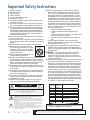 2
2
-
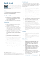 3
3
-
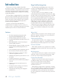 4
4
-
 5
5
-
 6
6
-
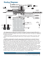 7
7
-
 8
8
-
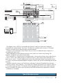 9
9
-
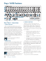 10
10
-
 11
11
-
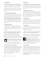 12
12
-
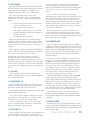 13
13
-
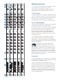 14
14
-
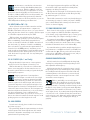 15
15
-
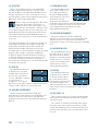 16
16
-
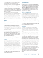 17
17
-
 18
18
-
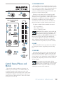 19
19
-
 20
20
-
 21
21
-
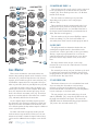 22
22
-
 23
23
-
 24
24
-
 25
25
-
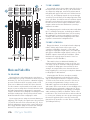 26
26
-
 27
27
-
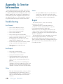 28
28
-
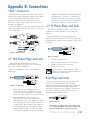 29
29
-
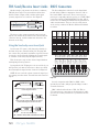 30
30
-
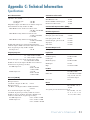 31
31
-
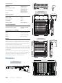 32
32
-
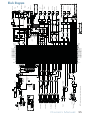 33
33
-
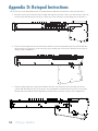 34
34
-
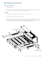 35
35
-
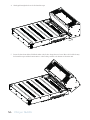 36
36
-
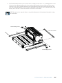 37
37
-
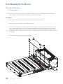 38
38
-
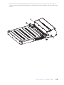 39
39
-
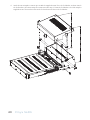 40
40
-
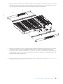 41
41
-
 42
42
-
 43
43
-
 44
44
-
 45
45
-
 46
46
-
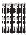 47
47
-
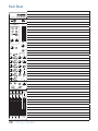 48
48
-
 49
49
-
 50
50


Ask a question and I''ll find the answer in the document
Finding information in a document is now easier with AI