
INSTRUCTIONS
BEDIENUNGSANLEITUNG
MANUEL D’INSTRUCTIONS
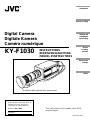
Digital Camera
Digitale Kamera
Caméra numérique
KY-F1030
Illustration with optional lens attachment.
This instruction book is made from 100%
recycled paper.
LWT0016-001A
For Customer Use:
Enter below the Serial No. which is
located on the unit. Retain this
information for future reference.
Model No. KY-F1030
Serial No.
Introduction
Before recording
Settings and
adjustments
for recording
Various
recording
methods
Menu screen
settings
Others

1. Read all of these instructions.
2. Save these instructions for later use.
3. All warnings on the product and in the operating instructions should be adhered to.
4. Unplug this appliance system from the wall outlet before cleaning. Do not use liquid
cleaners or aerosol cleaners. Use a damp cloth for cleaning.
5. Do not use attachments not recommended by the appliance manufacturer as they may
cause hazards.
6. Do not use this appliance near water - for example, near a bathtub, washbowl, kitchen
sink, or laundry tub, in a wet basement, or near a swimming pool, etc.
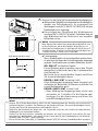
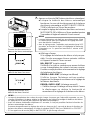
7. Do not place this appliance on an unstable cart, stand, or table. The
appliance may fall, causing serious injury to a child or adult, and
serious damage to the appliance.
Use only with a cart or stand recommended by the manufacturer, or
sold with the appliance. Wall or shelf mounting should follow the
manufacturer’s instructions, and should use a mounting kit approved
by the manufacturer. An appliance and cart combination should be
moved with care.
Quick stops, excessive force, and uneven surfaces may cause the
appliance and cart combination to overturn.
8. Slots and openings in the cabinet and the back or bottom are provided for ventilation,
and to insure reliable operation of the appliance and to protect it from overheating,
these openings must not be blocked or covered. The openings should never be blocked
by placing the appliance on a bed, sofa, rug, or other similar surface.
This appliance should never be placed near or over a radiator or heat register. This
appliance should not be placed in a built-in installation such as a bookcase unless
proper ventilation is provided.
9. This appliance should be operated only from the type of power source indicated on the
marking label. If you are not sure of the type of power supplied to your home, consult
your dealer or local power company. For appliance designed to operate from battery
power, refer to the operating instructions.
10. This appliance system is equipped with a 3-wire grounding type plug (a plug having a
third (grounding) pin). This plug will only fit into a grounding-type power outlet. This is a
safety feature. If you are unable to insert the plug into the outlet, contact your electrician
to replace your obsolete outlet. Do not defeat the safety purpose of the grounding plug.
11. For added protection for this product during a lightning storm, or when it is left unattended
and unused for long periods of time, unplug it from the wall outlet and disconnect the
antenna or cable system. This will prevent damage to the product due to lightning and
power-line surges.
12. Do not allow anything to rest on the power cord. Do not locate this appliance where the
cord will be abused by persons walking on it.
IMPORTANT SAFEGUARDS
PORTABLE CART WARNING
(symbol provided by RETAC)
S3126A
I

13. Follow all warnings and instructions marked on the appliance.
14. Do not overload wall outlets and extension cords as this can result in fire or electric
shock.
15. Never push objects of any kind into his appliance through cabinet slots as they mat
touch dangerous voltage points or short out parts that could result in a fire or electric
shock. Never spill liquid of any kind on the appliance.
16. Do not attempt to service this appliance yourself as opening or removing covers may
expose you to dangerous voltage or other hazards. Refer all servicing to qualified service
personnel.
17. Unplug his appliance from the wall outlet and refer servicing to qualified service personnel
under following conditions:
a. When the power cord or plug is damaged or frayed.
b. If liquid has been spilled into the appliance.
c. If the appliance has been exposed to rain or water.
d. If the appliance does not operate normally by following the operating instructions.
Adjust only those controls that are covered by the operating instructions as improper
adjustment of other controls may result in damage and will often require extensive
work by a qualified technician to restore the appliance to normal operation.
e. If the appliance has been dropped or the cabinet has been damaged.
f. When the appliance exhibits a distinct change in performance - this indicates a need
for service.
18. When replacement parts are required, be sure the service technician has used
replacement parts specified by the manufacturer that have the same characteristics as
the original part. Unauthorized substitutions may result in fire, electric shock, or other
hazards.
19. Upon completion of any service or repairs to this appliance, ask the service technician
to perform routine safety checks to determine that the appliance is in safe operating
condition.
II

1. JVC PROFESSIONAL PRODUCTS (U.K.) LIMITED
ULLSWATER HOUSE, KENDAL AVENUE
LONDON, W3 0XA, UNITED KINGDOM
TEL : 020 8896 6000
2. JVC PROFESSIONAL PRODUCTS GMBH
GRÜENER WEG 12, 61169 FRIEDBERG / HESSEN GERMANY
TEL : (06031)6050
3. JVC PROFESSIONAL PRODUCTS ITALIA S.p.A.
VIA MARIO PANNUNZIO 4, 20156 MILANO, ITALY
TEL : (02)38.05.01
4. JVC FRANCE S.A.
1, AVENUE EIFFEL 78422 CARRIERES-SUR-SEINE, CEDEX FRANCE
TEL : 33.1.61.04.11.64.
5. JVC ESPAÑA S.A.
CTRA GRACIA MANRESA,KM 14 750 EDIFICIO CAN CASTANYER
08190 SANT CUGAT DEL VALLES (BARCELONA) SPAIN
TEL : (93)5653210
6. JVC BELGIUM S.A./N.V.
RUE DE LA PETITE LLE 3, KLEIN-EILANDSTRAAT,
BRUXELLES 1070 BRUSSEL, BELGIUM
TEL : (02)529-4211
7. JVC NEDERLAND B.V.
JVC PLEIN DE HEYDERWEG 2, 2314 XZ LEIDEN, NEDERLAND
TEL : (071)5453333
8. JVC SVENSKA AB
VEDDESTAVAGEN 15, S-175 62 JARFALLA-STOCKHOLM, SWEDEN
TEL : (08)7950400
9. JVC NORGE A/S
P.O.BOX 2012, POSTTERMINALEN 3103, TONSBERG, NORWAY
TEL : (333)61600
III
JVC Sales Office

IV
10. JVC DENMARK A/S
HELGESHOJ ALLE 30 DK-2630, TASTRUP, DENMARK
TEL : (43)509000
11. SPITZER ELECTRONIC AG
MUHLEMATTSTRASSE 13, 4104 OBERWIL, SWITZERLAND
TEL : 0614051111
12. OY HEDPRO AB
LAUTTASAARENTIE 50, FIN-00200 HELSINKI, FINLAND
TEL : 35896828244
13. ELECTROINDUSTRIAL HELLAS S.A.
62, PIRAEUS AVE, 183 46 MOSCHATO, ATHENS, GREECE
TEL : (01)4832855
14. ORIELA S.A.
CAMPO STA. CLARA 160-A, 1100 LISBOA PORTUGAL
TEL : 351-1-882-3382
15. FACO HF
FAXAFEN 12, P.O.BOX 442, 108 108 REYKAJVIK, ICELAND
TEL : 91-588-3050

E2
Thank you for purchasing the JVC KY-F1030
Digital Camera.
These instructions are for KY-F1030U.
The instructions are given in three languages:
English from page E2 to E46
German from page G2 to G46
French from page F2 to F46
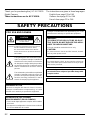
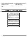
SAFETY PRECAUTIONS
FOR USA AND CANADA
The lightning flash with arrowhead symbol,
within an equilateral triangle is intended to
alert the user to the presence of uninsulat-
ed “dangerous voltage” within the product’s
enclosure that may be of sufficient magni-
tude to constitute a risk of electric shock to
persons.
The exclamation point within an equilateral
triangle is intended to alert the user to the
presence of important operating and main-
tenance (servicing) instructions in the lit-
erature accompanying the appliance.
CAUTION: TO REDUCE THE RISK OF ELECTRIC SHOCK,
DO NOT REMOVE COVER (OR BACK).
NO USER SERVICEABLE PARTS INSIDE.
REFER SERVICING TO QUALIFIED SERVICE
PERSONNEL.
Information for USA
This device complies with Part 15 of the FCC Rules.
Changes or modifications not approved by JVC could
void the user’s authority to operate the equipment.
INFORMATION (FOR CANADA)
RENSEIGNEMENT (POUR CANADA)
• This Class B digital apparatus complies with Canadian
ICES-003.
• Cet appareil numérique de la classe B est conforme
à la norme NMB-003 du Canada.
Changes or modifications not approved by JVC could
void the user’s authority to operate the equipment.
WARNING:
TO REDUCE THE RISK OF FIRE OR ELEC-
TRIC SHOCK, DO NOT EXPOSE THIS APPLI-
ANCE TO RAIN OR MOISTURE.
This unit should be used with 12V DC only.
CAUTION:
To prevent electric shocks and fire hazards, do NOT
use any other power source.
Due to design modifications, data given in this in-
struction book are subject to possible change with-
out prior notice.
CAUTION:
To prevent electric shock, do not open the cabinet. No
user serviceable parts inside. Refer servicing to quali-
fied service personnel.
This unit is designed for professional use only.
RISK OF ELECTRIC SHOCK
DO NOT OPEN
CAUTION

E3
For Sweden
VARNING
Explosionsfara vid felaktigt batteribyte.
Använd samma batterityp eller en ekvivalent typ
som rekommenderas av apparattillverkaren.
Kassera använt batteri enligt fabrikantens
instruktion.
For Norway
ADVARSEL
Lithiumbatteri – Eksplosjonsfare.
Ved utskifting benyttes kun batteri som anbefalt
av apparatfabrikanten.
Brukt batteri returneres apparatieverandøren.
For Denmark
ADVARSELI
Lithiumbatteri – Eksplosionsfare ved fejlagtig
håndtering.
Udskiftning må kun ske med batteri af samme
fabrikat og type.
Lever det brugte batteri tilbage til leverandøren.
For Finland
VAROITUS
Paristo voi räjähtää, jos se on virheellisesti
asennettu.
Vaihda paristo ainoastaan laltevalmistajan
suoaittelemaan tyyppiin. Hävitä käytetty paristo
valmistajan ohjeiden mukaisesti.
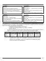
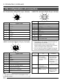
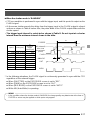
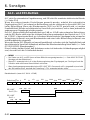
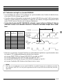
This equipment is in conformity with the provisions and protection requirements of the corre-
sponding European Directives. This equipment is designed for professional video appliances
and can be used in the following environments.
• residential area (in houses) or rural area
• commercial and light industry; e.g. offices or theatres
• urban outdoors
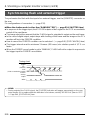
In order to keep the best performance and furthermore for electromagnetic compat-
ibility we recommend to use cables not exceeding the following length:
Caution : Where there are strong electromagnetic waves or magnetism, for
example near a radio or TV transmitter, transformer, motor, etc., the
picture may be disturbed. In such case, please keep the apparatus away
from the sources of the disturbance.
Port Cable Length Port Cable Length
DC IN Exclusive Cable 2 meters MONITOR Monitor Cable 2 meters
LENS Cable of LENS 0.4 meter IEEE1394
IEEE1394 Cable
4.5 meters
REMOTE Single wire 5 meters
MD CONTROL
MD CONTROL Cable
0.6 meters

E4
Table of Contents
1. Introduction
Features ...........................................................................................................................6
Accessories and attachments ..........................................................................................7
Cautionary notes for the correct usage of this product ....................................................8
Part names and their functions ........................................................................................9
Pin configurations of connectors ....................................................................................12
2. Before shooting
Connecting through digital output connector..................................................................14
Connecting through analog output connector ................................................................15
Combining with a presentation system ..........................................................................16
Mounting the lens...........................................................................................................17
Connecting power ..........................................................................................................18
Connecting the IEEE 1394 Cable ..................................................................................18
Mounting the camera .....................................................................................................19
Fall prevention ................................................................................................................20
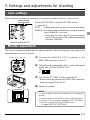
3. Settings and adjustments for shooting
Lens settings ..................................................................................................................21
Monitor adjustment.........................................................................................................21
White balance adjustment..............................................................................................22
Focus adjustment...........................................................................................................24
4. Shooting a computer monitor screen
Shooting a PC monitor ...................................................................................................25
Synchronizing flash and External Trigger.......................................................................26
White spot compensation...............................................................................................28
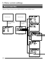
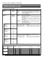
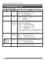
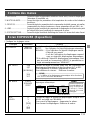
5. Menu screen settings
Menu screen flow ...........................................................................................................30
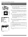
Setting procedure...........................................................................................................32
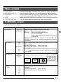
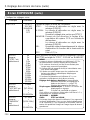
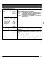
Menu contents................................................................................................................33
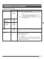
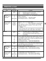
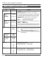
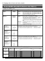
EXPOSURE screen .......................................................................................................33
WHITE BALANCE screen ..............................................................................................36
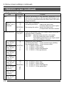
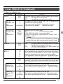
PROCESS screen..........................................................................................................37
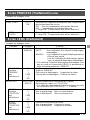
LENS screen ..................................................................................................................39
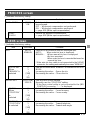
SYSTEM SETTING screen ............................................................................................40
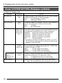
MENU (QUICK) screen ..................................................................................................41
Resetting menu settings.................................................................................................43

E5
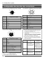
CAUTION Cautionary notes concerning operation of the unit
MEMO Reference such as restrictions of features, etc.
Reference page or item
In general, the names of products manufactured by other companies and mentioned in these
instructions are trademarks or registered trademarks of these companies.
Symbols like , , , etc., are not used in these instructions.
Characters and symbols used in this instruction book
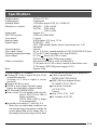
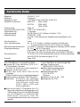
6. Others
About ALC and EEI operations ......................................................................................44
Specifications .................................................................................................................45

E6
Features
● The KY-F1030 is a digital camera employing a 1/2” CCD with 1.45 million effective pixels.
● Employment of RGB primary color filter CCD for color adjustment close to that of 3-CCD
cameras.
● Output of 1360 × 1024-pixel digital/analog video signal possible.
● Built-in DSP for real-time processing of the video signal that is output as a 7.5 frames-per-
second Y, Cb, Cr 4:2:2 digital signal enables real-time transfer to personal computer by means
of IEEE1394 host adapter.
● Using the designated scan rate converter enables display of the analog output on an SXGA-
compliant monitor.
● Built-in IEEE1394 connector enables remote control from personal computer. (Software pro-
vided.)
1. Introduction

E7
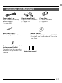
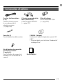
Instruction manual
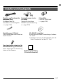
Accessories and attachments
Clamp filter
For IEEE1394 cable
( page E18)
Power cable (2 m)
8-pin cable for connecting
with AC adapter.
( page E18)
Remote plug (10-pin)
Plug for REMOTE terminal
( page E12)
Camera mounting bracket
locking screw (3 units)
For attaching the mounting
bracket on the top surface of the
camera.
CD-ROM (1 disk)
Contains special application software “KY-LINK”.
* For details, see the “Readme.txt” file on the
disc “Enu”.
Wire clamp (5 pcs.)
For clamping cables on the rear.

E8
Cautionary notes for the correct usage of this product
• Before recording an important event, etc., always check to make sure that this product is
working properly.
• We are not liable for any missed recordings caused by malfunction of this unit, etc.
Phenomena unique to CCD
• Smearing and blooming
When using CCD to shoot a bright light source, a smearing effect may occur running a
white line vertical to the light source. In addition, a blooming effect may also occur when the
light source is extremely bright, spreading light to the source surroundings.
• Line distortion
Line and patterns may appear distorted when shot.
• White spots
White spots may appear on the screen when operating under high temperatures. Always
use the product under recommended ambient temperatures.
White spots may also appear at a slow shutter speed setting (1/8 s or higher).
To reduce this phenomenon, this product is provided with at built-in white spot compensa-
tion function. ( Z page E28 White spot compensation)
Cautionary notes
• Influence of strong electric waves and magnets
Screen noise and discolouration may occur when using the product near antennas of ra-
dios and televisions or near transformers, monitors, etc. with strong magnetic force.
• Compatible lenses ( page E17 Mounting the lens)
Although the lens mount of this product is a type C mount, take caution as there are restric-
tions on the lenses that can be used.
• To save electricity, turn off the system when not in use.
Cleaning
When clean the equipment please use dry cleaning cloth or wet cleaning cloth with small
amount of alcohol.
Do not spill any liquid into KY-F1030.
Do not install the KY-F1030 in a location where it is subject to radiation or x-rays or
where corrosive gasses are generated.
1. Introduction (continued)

E9
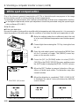
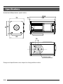
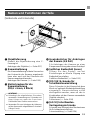
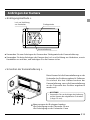
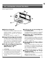
Part names and their functions
쐃 Lens mount
Although the lens mount conforms to the
type C mount lens.
Mounting the lens ( page E17)
쐇 Camera mounting bracket
Although the mounting bracket is mounted
on the bottom of the camera when shipped,
the bracket can also be mounted on the
top of the camera.
Mounting the camera ( page E19)
쐋 Locking screws for the camera
mounting bracket
(M2.6 × 6mm, 3 units)
CAUTION
● Always use the attached screws. Using
screws that exceed 6mm may result in mal-
function of the unit.
● When the bracket is mounted on the top sur-
face of the camera, use the provided screws
(length: 10 mm).
쐏 Screw holes for mounting the
camera (1/4-inch)
Used when mounting the camera to a fixer
or rotating platform.
쐄 Side switch panel (inside)
Open the door to access a switch panel
used when making settings on menus.
Side switch panel section ( page E11)
쐂 [FOCUS] backfocus adjustment
screw
This is adjusted to the optimal wide setting
when shipped from the factory. Should be
readjusted when required by the lens used
in combination with the camera.
Focus adjustment ( page E24)
쐆 [LOCK] backfocus locking screw
Screw to lock the backfocus adjustment
mechanism.
Focus adjustment ( page E24)
[Front and bottom]
쐃
쐇
쐋
쐏
쐄
쐂
쐆

E10
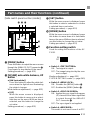
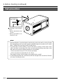
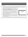
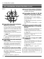
[Rear]
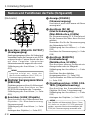
쐈 [POWER] indicator
Lights when power is supplied to the cam-
era.
쐉 [DC IN] connector
(Mini DIN 8-pin, female)
Power (DC 12V) for the camera is supplied
through this inlet.
For the power supply, use the AA-P700 AC
adapter.
Pin configurations of connectors ( page
E12)
Connecting power ( page E18)
씈 [REMOTE] terminal
(Metal 10-pin, female)
Used to connect external devices such as
a trigger switch or flash unit.
Pin configurations of connectors ( page
E12)
Connecting through digital output connec-
tor ( page E14)
Synchronizing flash and trigger ( page
E26)
씉 [MD CONTROL] lens connector
2
To connect the lens control cable (for zoom,
focusing control).
Pin configurations of connectors ( page
E12)
Mounting the lens ( page E17)
ANALOG OUT
IEEE1394
LENS
MD
CONTROL
REMOTE
DC IN
POWER
SEE INSTRUCTION MANUAL
쐉씈
씉쐅
쐊쐎
쐈
1. Introduction (continued)
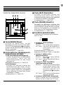
쐊 [ANALOG OUTPUT] connector
Analog output connector for video signal.
Used when connecting the camera to an
SXGA-compliant capture board or the des-
ignated scan rate converter integrated with
the computer.
Pin configurations of connectors ( page
E13)
MEMO
Only output when the AC adapter (AA-
P700) is used as the power supply.
쐎 [IEEE1394] digital output con-
nector
Digital output connector for video signal.
Used when connecting to the PC’s IEEE
1394 host adapter.
Pin configurations of connectors ( page
E13)
쐅 [LENS] connector 1
To connect the lens’ camera cable (for iris
control, power supply).
Pin configurations of connectors ( page
E12)
Mounting the lens ( page E17)
MEMO
The motorized lens can only be controlled
(zoom, IRIS, focus) from the KY-F1030 when
the AC adapter (AA-P700) is used as the power
supply.

E11
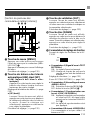
Part names and their functions (continued)
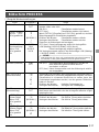
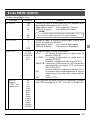
씊 [MENU] button
Press this button to output the menu screen
through the [ANALOG OUT] connector .
Press again to stop display of the menu.
Setting procedure ( page E32)
씋 [UP/AW] auto white balance, UP
button
● [AW (auto white)]
Press this button to adjust the white bal-
ance when the light source illuminating
the subject changes.
White balance adjustment ( page E22)
● [UP]
While the menu screen is displayed,
press this button to move up to a select-
able item on the menu. While an item is
selected, use this button to change the
set value.
Setting procedure ( page E32)
[Side switch panel section (inside)] 씌 [SET] button
While the menu screen is displayed, press
this button to select a submenu or confirm
a selected item or set value.
Setting procedure( page E32)
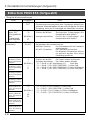
씍 [DOWN] button
While the menu screen is displayed, press
this button to move down to a selectable
item on the menu. While an item is selected,
use this button to change the set value.
Setting procedure( page E32)
씎 Function setting switch
Used for setting the functions of the KY-
F1030.
● Switch 1 <TEST PATTERN>
ON: Test signal is output.
OFF: The image being shot by the cam-
era is output.
Monitor adjustment ( page E21)
SYSTEM SETTING screen ( page E40)
● Switch 2 <MENU LOCK>
ON: Disables the [MENU] button 씊.
OFF: Enables the [MENU] button 씊.
● Switch 3 <SYNC ON GREEN>
ON: Applies the sync signal to the green
(G) channel of the video signal that
is output through the ANALOG
OUT connector 쐊.
OFF: The sync signal is not applied.
● Switch 4 <RESERVED>
This switch is not used. Leave it at OFF.
UP/AW
SET
MENU
DOWN
1234
씊씋씌
씍
씎
ON
OFF
1234

E12
1
4
3
6
7
8
5
2
1. Introduction (continued)
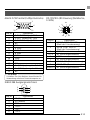
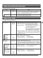
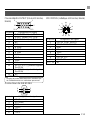
DC IN terminal (Mini DIN 8-pin, female)
Pin configurations of connectors
Pin no. Signal name
1NC
2 GND
3NC
4NC
5 GND
6 12V
7NC
8 12V
LENS terminal (Metal 12-pin, female)
Pin no. Signal name
1NC
2NC
3 GND
4NC
5 IRIS CONTROL
6 12V DC 400mA max.
7 IRIS POSITION
8 IRIS AUTO /MANU
9 to 12 NC
6
7
8
2
1
9
3
4
12
5
10
11
Terminal
name
2 TRG IN
3 WEN
4 FLASH
REMOTE terminal (Metal 10-pin, female)
Pin no. Signal name
1 A. WHITE L active
2 TRG IN L active
3
WEN L active 3.3V(p-p)
4 FLASH
5NC
6 RS-SDI
7 RS-SDO
8 GND
9 12V
10 OPERATION
1
2
8
7
10
6
3
4
5
9
CAUTION
• Consult your JVC dealer concerning the re-
mote terminal connection.
• Remote cable must use shielded cable.
Outer shield of remote cable must to connect
10-pin connector outer metal shell.
• Do not input the external trigger during the
first 5 seconds after the power is turned ON.
I/O
IN
• 3.3V CMOS
• Schmidt Trigger
• Pull-up to 3.3V at
4.7k Ω
OUT
• 3.3V (p-p)
negative polarity
OUT
• Open collector
Conditions
• Contact point
recommended
• Maximum rated
voltage: 5.3V
• H level: 2.4 ~ 5.0V
• L level: 0 ~ 0.5V
• Pulse width:
130 µs or higher
• Maximum rated
current: 150mA
• Maximum rated
voltage: 12V
CAUTION
Use device whose current consumption is max.
400 mA or less.

E13
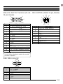
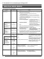
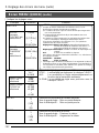
ANALOG OUTPUT terminal (D-sub
15-pin, female)
Pin no. Signal name
1 R OUT 700mV
(p-p)
, 75 Ω
2 G OUT 700mV
(p-p)
, 75 Ω
3 B OUT 700mV
(p-p)
, 75 Ω
4NC
5NC
6 R GND
7 G GND
8 B GND
9WEN
10 GND
11 GND
12 NC
13 Hs (3.3V(p-p) negative polarity)
14 Vs (3.3V(p-p) negative polarity)
15 NC
MD CONTROL (Metal 12-pin, female)
15
10
6
11
15
CAUTION
Do not connect directly to monitor for use with
personal computers.
IEEE1394 connector
Pin no. Signal name
1
VP (Current)
2
VG (GND)
3
TPB –
4
TPB +
5
TPA –
6
TPA +
Pin no. Signal name
1
FOCUS CONT SELECT
2
ZOOM CONT SELECT
3 GND
4
~ 5
NC
6
+12 V
7NC
8
FOCUS CTL
9
ZOOM CTL
10
~
12 NC
2
4
6
1
3
5

E14
AC ADAPTER AA-P700
ON
OFF
POWER
AA-P700
AC
[IEEE1394]
[REMOTE]
[DC IN]
FOCUS
LOCK
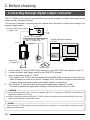
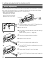
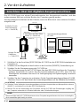
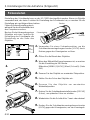
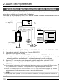
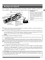
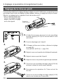
2. Before shooting
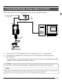
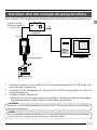
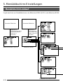
Connecting through digital output connector
The KY-F1030 can be remote-controlled from a personal computer, and the shot image can be
shown on the computer’s monitor.
<Connection Example> Shooting with the camera when the flash is fired by the timing of an
external trigger switch.
1. Connect the KY-F1030’s [IEEE1394] connector to the IEEE1394 host adapter on the PC.
2. Connect the flash and trigger switch to the [REMOTE] terminal.
3. Turn on the power of the KY-F1030.
* The power for KY-F1030 can be supplied from the IEEE1394 connector of personal com-
puter. However, be sure to use the AC adapter (AA-P700) when using the motorized lens
or when using both analog output and digital output in combination.
4. Turn ON the PC, and then start up the special application software KY-LINK.
*For how to operate the application software, see the Help file of the KY-LINK.
Connect to the power supply
( page E18)
AC adapter
Attach lens
( page E17)
Connecting the IEEE1394
Cable ( page E18)
Flash
Trigger switch
Special application software
KY-LINK
PC
IEEE1394
host
adapter
CAUTION
● Do not turn the power switch on the AC adapter ON/OFF or unplug the IEEE1394 cable while the
application software is running.
● Before using the computer with the KY-F1030, release any settings that automatically set the com-
puter in the Stand by or Hibernate mode.
MEMO
If two or more KY-F1030 cameras are connected to one computer, it is not possible to view the camera
images simultaneously.

E15
AC ADAPTER AA-P700
ON
OFF
POWER
FOCUS
LOCK
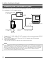
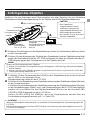
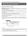
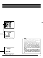
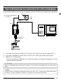
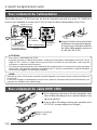
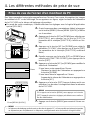
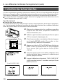
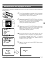
Connecting through analog output connector
The image shot by the KY-F1030 can be shown on the computer’s monitor.
AC adapter
Connect the power supply
( page E18)
MEMO
When the shutter speed becomes slower (slower than 1/7.5s), the image may be seen interrupted.
Also, the image will not freeze even when the external trigger switch is pressed.
PC
Video
capture
board
Microscope
adapter
1. Connect the KY-F1030’s [ANALOG OUT] connector to the PC’s capture board.
2. Connect the AC adapter (AA-P700) to the KY-F1030, and then turn ON the power.
3. Turn ON the PC.
*For instructions on how to operate the video capture board or the employed application
software, see the respective instruction manual.
CAUTION
Use a 1/2-inch C-mount microscope adapter compatible with the microscope to be employed.

E16
AC ADAPTER AA-P700
ON
OFF
POWER
FOCUS
LOCK
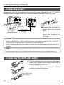
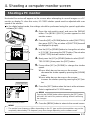
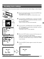
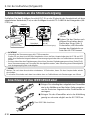
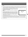
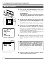
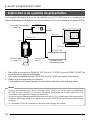
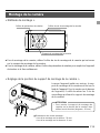
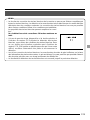
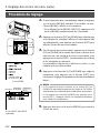
Combining with a presentation system
2. Before shooting (continued)
The image shot by the KY-F1030 can be passed though a scan rate converter and shown on a
D-ILA presenter or SXGA-compliant monitor.
MEMO
• When connected to the PC through the [IEEE1394] connector, or an RS-232C device is connected to
the [REMOTE] terminal, the auto white balance function of the scan rate converter will be disabled.
• When the shutter speed becomes slower (slower than 1/7.5s), the image may be seen interrupted.
• The image will not freeze even when the scan rate converter’s [FREEZE] button is pressed.
• The scan rate converter’s [SEND] command is invalid.
Connect the power supply
( page E18)
AC adapter
Mount the lens
( page E17)
Scan rate converter
JVC KM-F700
D-ILA or SXGA-compliant monitor
[VIDEO INPUT]
terminal
1. Connect the KY-F1030’s [ANALOG OUT] connector to the scan rate converter’s [VIDEO
INPUT] terminal.
2. Connect the AC adapter (AA-P700) to the KY-F1030, and then turn ON the power.
3. Turn ON the other devices.
* Also see the instructions for the scan rate converter to be used.
Page is loading ...
Page is loading ...
Page is loading ...
Page is loading ...
Page is loading ...
Page is loading ...
Page is loading ...
Page is loading ...
Page is loading ...
Page is loading ...
Page is loading ...
Page is loading ...
Page is loading ...
Page is loading ...
Page is loading ...
Page is loading ...
Page is loading ...
Page is loading ...
Page is loading ...
Page is loading ...
Page is loading ...
Page is loading ...
Page is loading ...
Page is loading ...
Page is loading ...
Page is loading ...
Page is loading ...
Page is loading ...
Page is loading ...
Page is loading ...
Page is loading ...
Page is loading ...
Page is loading ...
Page is loading ...
Page is loading ...
Page is loading ...
Page is loading ...
Page is loading ...
Page is loading ...
Page is loading ...
Page is loading ...
Page is loading ...
Page is loading ...
Page is loading ...
Page is loading ...
Page is loading ...
Page is loading ...
Page is loading ...
Page is loading ...
Page is loading ...
Page is loading ...
Page is loading ...
Page is loading ...
Page is loading ...
Page is loading ...
Page is loading ...
Page is loading ...
Page is loading ...
Page is loading ...
Page is loading ...
Page is loading ...
Page is loading ...
Page is loading ...
Page is loading ...
Page is loading ...
Page is loading ...
Page is loading ...
Page is loading ...
Page is loading ...
Page is loading ...
Page is loading ...
Page is loading ...
Page is loading ...
Page is loading ...
Page is loading ...
Page is loading ...
Page is loading ...
Page is loading ...
Page is loading ...
Page is loading ...
Page is loading ...
Page is loading ...
Page is loading ...
Page is loading ...
Page is loading ...
Page is loading ...
Page is loading ...
Page is loading ...
Page is loading ...
Page is loading ...
Page is loading ...
Page is loading ...
Page is loading ...
Page is loading ...
Page is loading ...
Page is loading ...
Page is loading ...
Page is loading ...
Page is loading ...
Page is loading ...
Page is loading ...
Page is loading ...
Page is loading ...
Page is loading ...
Page is loading ...
Page is loading ...
Page is loading ...
Page is loading ...
Page is loading ...
Page is loading ...
Page is loading ...
Page is loading ...
Page is loading ...
Page is loading ...
Page is loading ...
Page is loading ...
Page is loading ...
Page is loading ...
Page is loading ...
Page is loading ...
Page is loading ...
Page is loading ...
Page is loading ...
Page is loading ...
Page is loading ...
Page is loading ...
Page is loading ...
Page is loading ...
-
 1
1
-
 2
2
-
 3
3
-
 4
4
-
 5
5
-
 6
6
-
 7
7
-
 8
8
-
 9
9
-
 10
10
-
 11
11
-
 12
12
-
 13
13
-
 14
14
-
 15
15
-
 16
16
-
 17
17
-
 18
18
-
 19
19
-
 20
20
-
 21
21
-
 22
22
-
 23
23
-
 24
24
-
 25
25
-
 26
26
-
 27
27
-
 28
28
-
 29
29
-
 30
30
-
 31
31
-
 32
32
-
 33
33
-
 34
34
-
 35
35
-
 36
36
-
 37
37
-
 38
38
-
 39
39
-
 40
40
-
 41
41
-
 42
42
-
 43
43
-
 44
44
-
 45
45
-
 46
46
-
 47
47
-
 48
48
-
 49
49
-
 50
50
-
 51
51
-
 52
52
-
 53
53
-
 54
54
-
 55
55
-
 56
56
-
 57
57
-
 58
58
-
 59
59
-
 60
60
-
 61
61
-
 62
62
-
 63
63
-
 64
64
-
 65
65
-
 66
66
-
 67
67
-
 68
68
-
 69
69
-
 70
70
-
 71
71
-
 72
72
-
 73
73
-
 74
74
-
 75
75
-
 76
76
-
 77
77
-
 78
78
-
 79
79
-
 80
80
-
 81
81
-
 82
82
-
 83
83
-
 84
84
-
 85
85
-
 86
86
-
 87
87
-
 88
88
-
 89
89
-
 90
90
-
 91
91
-
 92
92
-
 93
93
-
 94
94
-
 95
95
-
 96
96
-
 97
97
-
 98
98
-
 99
99
-
 100
100
-
 101
101
-
 102
102
-
 103
103
-
 104
104
-
 105
105
-
 106
106
-
 107
107
-
 108
108
-
 109
109
-
 110
110
-
 111
111
-
 112
112
-
 113
113
-
 114
114
-
 115
115
-
 116
116
-
 117
117
-
 118
118
-
 119
119
-
 120
120
-
 121
121
-
 122
122
-
 123
123
-
 124
124
-
 125
125
-
 126
126
-
 127
127
-
 128
128
-
 129
129
-
 130
130
-
 131
131
-
 132
132
-
 133
133
-
 134
134
-
 135
135
-
 136
136
-
 137
137
-
 138
138
-
 139
139
-
 140
140
-
 141
141
-
 142
142
-
 143
143
-
 144
144
-
 145
145
-
 146
146
-
 147
147
-
 148
148


Ask a question and I''ll find the answer in the document
Finding information in a document is now easier with AI
in other languages
- français: JVC KY-F1030U Manuel utilisateur
- Deutsch: JVC KY-F1030U Benutzerhandbuch
Related papers
Other documents
-
Hama 00093720 Owner's manual
-
 MODWAY EEI-755-BLK Installation guide
-
 MODWAY EEI-757-BLK User manual
-
Hitachi KP-FD33GV Operating instructions
-
Indexa DF300SET Owner's manual
-
Hitachi HV-D25 User manual
-
-
-
Philips 719996148 Quick start guide
-

