DITEC Ditec NES1000EHP Owner's manual
- Category
- Gate Opener
- Type
- Owner's manual

Ditec NEOS
Sliding Gates
(Original instructions)
www.ditecentrematic.com
IP2160 EN
Technical Manual

2
IP2160EN - 2013-10-31
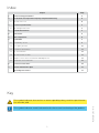
Index
Key
Subject Page
1. General safety precautions 4
2. Declaration of incorporation of partly completed machinery 5
2.1 Machine Directive 5
3 Technical specifications 6
3.1 Operating instructions 6
4. Standard installation 7
5. Dimensions 8
6. Main components 8
7. Installation 9
7.1 Preliminary checks 9
7.2 Base plate position 10
7.3 Gearmotor installation 11
7.4 Rack installation 12
7.5 Operation with encoder 13
7.6 Magnetic limit switch installation and adjustment 13
7.7 Chain drive kit installation 14
8. Electrical connections 15
9. Routine maintenance plan 16
Operating instructions 17
i
This symbol indicates instructions or notes regarding safety, to which special atten-
tion must be paid.
This symbol indicates useful information for the correct functioning of the product.

3
IP2160EN - 2013-10-31
1. General safety precautions
This installation manual is intended for qualified personnel only.
Installation, electrical connections and adjustments must be performed in accordance with
Good Working Methods and in compliance with the present standards.
Read the instructions carefully before installing the product.
Bad installation could be dangerous.
The packaging materials (plastic, polystyrene, etc.) should not be discarded in the environ-
ment or left within reach of children, as these are a potential source of danger.
Before installing the product, make sure it is in perfect condition.
Do not install the product in explosive areas and atmospheres: the presence of inflammable
gas or fumes represents a serious safety hazard.
Before installing the motorisation device, make all the necessary structural modifications in
order to create safety clearance and to guard or isolate all the crushing, shearing, trapping
and general hazardous areas.
Make sure the existing structure is up to standard in terms of strength and stability. The mo-
torisation device manufacturer is not responsible for failure to observe Good Working Methods
when building the frames to be motorised or for any deformation during use.
The safety devices (photocells, safety edges, emergency stops, etc.) must be installed taking
into account: applicable laws and directives, Good Working Methods, installation premises,
system operating logic and the forces developed by the motorised door.
The safety devices must protect the crushing, cutting, trapping and general hazardous areas
of the motorised door.
Display the signs required by law to identify hazardous areas.
Each installation must bear a visible indication of the data identifying the motorised door.
When requested, connect the motorised door to an effective earthing system that complies
with current safety standards.
During installation, maintenance and repair operations, cut off the power supply before opening
the cover to access the electrical parts.
The automation protection casing must be removed by qualified personnel only.
The electronic parts must be handled using earthed antistatic conductive arms. The
manufacturer of the motorisation declines all responsibility in the event of component
parts being fitted that are not compatible with the safe and correct operation.
Use original spare parts only for repairs or replacements of products.
The installer must supply all information on automatic, manual and emergency operation of the
motorised door and must provide the user with the operating instructions.
Failure to observe the information in this manual may result
in minor personal injury or damage to equipment.
Save these instructions for future reference.

4
IP2160EN - 2013-10-31
2. Declaration of incorporation of partly
completed machinery
2.1 Machinery Directive
(Directive 2006/42/EC, Annex II-B)
The manufacturer Entrematic Group AB with headquarters in Lodjursgatan 10, SE-261 44 Land-
skrona, Sweden, declares that the automation for Ditec NEOS type sliding gate:
- has been constructed to be installed on a manual door to construct a machine pursuant to the
Directive 2006/42/EC. The manufacturer of the motorised door shall declare conformity pursu-
ant to the Directive 2006/42/EC (Annex II-A), prior to the machine being put into service;
- conforms to the applicable essential safety requirements indicated in ANNEX I, Chapter 1 of the
Directive 2006/42/EC;
- conforms to the Low Voltage Directive 2006/95/EC;
- conforms to the Electromagnetic Compatibility Directive 2004/108/EC:
- the technical documentation conforms to Annex VII-B of the Directive 2006/42/EC;
- the technical documentation is managed by Marco Pietro Zini with headquarters in Via Mons.
Banfi, 3 - 21042 Caronno Pertusella (VA) - ITALY;
- a copy of technical documentation will be provided to national competent authorities, following
a suitably justified request.
Landskrona, 08-03-2013 Marco Pietro Zini
(BA President)
Pursuant to Machinery Directive (2006/42/EC) the installer who motorises a door or gate has the
same obligations as the manufacturer of machinery and as such must:
- prepare the technical file which must contain the documents indicated in Annex V of the Machinery
Directive;
(The technical file must be kept and placed at the disposal of competent national authorities for
at least ten years from the date of manufacture of the motorised door);
- draw up the EC Declaration of Conformity in accordance with Annex II-A of the Machinery Direc-
tive and deliver it to the customer;
- affix the EC marking on the motorised door in accordance with point 1.7.3 of Annex I of the
Machine Directive.

5
IP2160EN - 2013-10-31
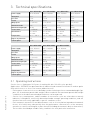
3. Technical specifications
3.1 Operating instructions
Service class: 4 (minimum 10÷5 years of working life with 100÷200 cycles per day).
Applications: INTENSE (for apartment block, industrial and commercial entrances and car parks
with vehicle access or access for intense pedestrian use).
- Performance characteristics are to be understood as referring to the recommended weight (ap-
prox. 2/3 of maximum permissible weight). When used with the maximum permissible weight
a reduction in the above mentioned performance can be expected.
- Service class, running times, and the number of consecutive cycles are to be taken as merely
indicative, having been statistically determined under average operating conditions, and are
therefore not necessarily applicable to specific conditions of use.
- Each automatic entrance has variable elements such as: friction, balancing and environmental
factors, all of which may substantially alter the performance characteristics of the automatic
entrance or curtail its working life or parts thereof (including the automatic devices themselves).
The installer should adopt suitable safety conditions for each particular installation.
Ditec NES300EH Ditec NES300EHP Ditec NES400EH Ditec NES400EHP
Power supply 230 V~ 50/60Hz 230 V~ 50/60Hz 230 V~ 50/60Hz 230 V~ 50/60Hz
Absorption 1,2 A 1,2 A 1,2 A 1,2 A
Line fuse F1,6 A F1,6 A F1,6 A F1,6 A
Thrust 300 N 300 N 400 N 400 N
Wing speed 0,1÷0,25 m/s 0,1÷0,25 m/s 0,1÷0,25 m/s 0,1÷0,25 m/s
Maximum stroke 12 m 12 m 12 m 12 m
Maximum wing weight 300 kg 300 kg 400 kg 400 kg
Service class 4 - INTENSE 4 - INTENSE 4 - INTENSE 4 - INTENSE
Intermittence S2 = 30 min
S3 = 50%
S2 = 30 min
S3 = 50%
S2 = 30 min
S3 = 50%
S2 = 30 min
S3 = 50%
Temperature -20° C - +55° C -20° C - +55° C -20° C - +55° C -20° C - +55° C
Degree of protection IP24 IP24 IP24 IP24
Control panel CS12E CS12M CS12E CS12M
Ditec NES600EH Ditec NES600EHP Ditec NES1000EHP
Power supply 230 V~ 50/60Hz 230 V~ 50/60Hz 230 V~ 50/60Hz
Absorption 1,5 A 1,5 A 2 A
Line fuse F2A F2A F2,5 A
Thrust 600 N 600 N 1000 N
Wing speed 0,1÷0,24 m/s 0,1÷0,24 m/s 0,1÷0,19 m/s
Maximum stroke 20 m 20 m 20 m
Maximum wing weight 600 kg 600 kg 1000 kg
Service class 4 - INTENSE 4 - INTENSE 4 - INTENSE
Intermittence S2 = 30 min
S3 = 50%
S2 = 30 min
S3 = 50%
S2 = 30 min
S3 = 50%
Temperature -20° C - +55° C -20° C - +55° C -20° C - +55° C
Degree of protection IP24 IP24 IP24
Control panel CS12E CS12M CS12M

6
IP2160EN - 2013-10-31
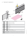
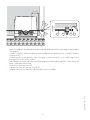
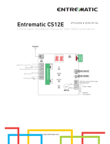
4. Standard installation
Ref. Code Description
1 NES300
NES400
NES600
NES1000
300 kg gearmotor with control panel
400 kg gearmotor with control panel
600 kg gearmotor with control panel
1000 kg gearmotor with control panel
2 GOL4
GOL4C
Remote control
3 LAMPH Flashing light
4 XEL5
LAN4
GOL4M
Key selector switch
Keypad
Wireless keypad
5 XEL2
LAB4
Photocells
IP55 photocells
6 SOFA-SOFB
GOPAV
Safety edge
Radio system for safety edges
7 LAB9 Magnetic loop detector for passage control
A Connect the power supply to a type-approved omnipolar switch, with a contact opening distance of at
least 3 mm (not supplied).
Connection to the mains must be via independent channels and separate from the connections to the
control and safety devices.
1 A
4
7
2
6
3
5
5

7
IP2160EN - 2013-10-31
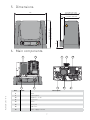
5. Dimensions
335
307 (NES 300-400)
325 (NES 600-1000)
90
210 (NES 300-400)
220 (NES 600-1000)
170 (NES 300-400)
180 (NES 600-1000)
40
6. Main components
Ref. Code Description
8 Motor
9 Control panel
10 Diagnostic circuit
11 Key release
12 Pinion
13 Battery kit
14 Cable inlet
15 Power supply terminal
8
11 10
9 8 13
91514
12

8
IP2160EN - 2013-10-31
7.1 Preliminary checks
Check the stability of the wing (derailing and lateral falls) and the sliding wheels and that the upper
guides do not cause any friction.
The sliding guide must be securely fixed to the ground for the full length within doorway and must
have no irregularities that could hinder the movement of the wing.
The opening and closing stops must be fitted.
If the gate has slits, make sure they are covered to prevent shearing points or install active safety
edges on the columns.
Safety device should be installed at the end of the wing to reduce the collision force.
N.B.: make sure that the gate can not exit the sliding guides and fall.
7. Installation
The given operating and performance features can only be guaranteed with the use of DITEC ac-
cessories and safety devices.
Unless otherwise specified, all measurements are expressed in mm.

9
IP2160EN - 2013-10-31
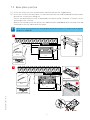
7.2 Base plate position
[1] Insert the anchor ties into the base plate and fix them with the supplied nuts.
[2] Insert the screws in the base plate, secure them with the nuts and then bend the metal tab to
prevent the screw from coming out.
Extract the preformed ties with a downwards movement using a hammer to ensure correct
anchorage to the concrete.
- Make a concrete base with the anchor ties and base plate embedded, which must be level and
clean and of the size indicated in the figure.
i
N.B.: if the concrete base has already been made, base plate [2] can be fixed using M8
plugs (not supplied).
OPENING
160
X+25 [*]
70[**]
min
40 [**]
Ø80
90°
300
335
1
[*] CROSSCRN2
[*] CROSSCRI
X=40
[**] NES100CKT
M12
low type
OPENING
160
X+25 [*]
70 [**]
Ø60
Ø9
min
40[**]
300
340
[*] CROSSCRN2
[*] CROSSCRI
X=40
[**] NES100CKT
1
2
2a
2b
NES100PSU
M12-low
type
M12
low type

10
IP2160EN - 2013-10-31
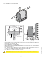
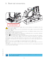
- Release the gearmotor (see OPERATING INSTRUCTIONS). Unscrew the front screw and remove
the casing by pressing on the side.
- Place the gearmotor on the base plate.
- Adjust the gearmotor horizontally by sliding it along the slots of the gearmotor base and vertically with
four levelling screws [A].
N.B.: during the vertical adjustment, keep the gearmotor slightly raised from the base plate
so that the rack can be fixed and subsequent adjustments are possible.
- After adjusting, fix the gearmotor using screws [B].
7.3 Gearmotor installation
WARNING: The gearmotor must be suitably raised from the ground to avoid flooding.
X
105
-15 +10
±5
A
B
M12-low type
M12
1
1
2

11
IP2160EN - 2013-10-31
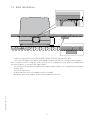
- Release the gearmotor (see OPERATING INSTRUCTIONS) and open the gate.
- Place the rack against the pinion and sliding the gate manually fix it along its whole length.
N.B.: To make it easier to align the rods correctly, use a scrap piece of rack and rest it underneath
the junction point, as shown in the figure detail.
- Once fixed, vertically adjust the gearmotor to give a play of about 2 to 3 mm between the pinion
and the rack.
- Secure the gearmotor.
- Slightly lubricate the rack and pinion after assembly.
Manually check that the gate slides evenly and without friction.
7.4 Rack installation
2÷3
95

12
IP2160EN - 2013-10-31
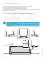
7.5 Operation with encoder
7.6 Magnetic limit switch installation and adjustment
NEOS gearmotors do not require limit switches because they have encoders.
Mechanical opening and closing end stops must be installed.
The gate automatically slows when approaching the end stops.
WARNING: when the gate reaches the opening or closing limit stop, it reverses briefly to facilitate
manual release of the gearmotor.
- Manually place the wing in the open position and fix limit switch brackets [A] and [B] on rack
[C]. Repeat this operation with the wing in the closed position.
- After a few manoeuvres, adjust the position of limit switch brackets [A] and [B] so that the gate
stops about 20 mm before reaching the opening and closing mechanical stops.
i
The limit switch kit is optional and is used to stop the gate before it reaches the opening
and closing mechanical stops.
With a limit switch installed, slowdown is carried out at regulated power to overcome
possible friction.
OPENING
~20
A BC

13
IP2160EN - 2013-10-31
1
12
- Release the gearmotor (see OPERATING INSTRUCTIONS).
- [1] Remove pinion [12].
- [2] Fix pinion supporting plate [A] to the gearmotor.
- Insert pinions [B] as illustrated in the diagram.
- [3] Pass the chain between the pinions by hand.
- Fix cover plate [C].
2
A
B
B
C
N.B.: Install the chain drive kit before securing the gearmotor to the base plate.
7.7 Chain drive kit installation
i

14
IP2160EN - 2013-10-31
- Move the wing into the open position by hand and fix brackets [D] on the wing as illustrated in
the diagram.
- Connect chain [E], which was previously assembled on the gearmotor, to tie rod [F] and fix it
to bracket [D].
- Fix bracket [D] on the opposite side of the gate. Connect chain [E] to tie rod [F] and fix it to
bracket [D] (cut the excess chain).
N.B.: Make sure that the distance between the pinion centre and tie rod [F] is correct when the
gate is fully open and closed.
- Secure the chain with nuts [G].
- Tighten the chain [E] with the tie rods [F].
- Slightly lubricate the chain [E] and the pinions after assembly.
min 50
40
E F D
G
E
F
G
D

15
IP2160EN - 2013-10-31
Before connecting the power supply, make sure the plate data correspond to that of the
mains power supply.
An omnipolar disconnection switch with minimum contact gaps of 3 mm must be included
in the mains supply.
Check that upstream of the electrical installation there is an adequate residual current circuit
breaker and a suitable overcurrent cutout.
Use a H05RN-F 3G1.5 or H05RR-F 3G1.5 type electric cable and connect it to terminals L (brown),
N (blue), (yellow/green) inside the automation.
Secure the cable using a special cable clamp and remove the sheath only where the clamp is.
Connection to the mains power supply, in the section outside the automation, is made with
independent channels and separated from the connections to the control and safety devices.
The channel must penetrate the automation through the holes on the base plate by a few cen-
timetres.
Make sure there are no sharp edges that may damage the power supply cable.
Make sure the mains power conductors (230 V) and accessory power conductors (24 V) are
separated.
The cables must be double insulated. Remove the sheath near the connecting terminals and
secure them with cable clamps.
N.B.: The electrical wiring and the start-up of the gearmotors are shown in the control
panel installation manuals.
i
8. Electrical connections
L
N
Make sure the yellow-green conductor
is at least 30 mm longer than the
brown and blue conductors

16
IP2160EN - 2013-10-31
Perform the following operations and checks every 6 months according to intensity of use of the
automation.
Disconnect the 230 V~ power supply and batteries (if fitted) and release the gearmotor:
- Visually check that the gate, the fixing brackets and existing structure have suitable mechanical
strength and are in good condition.
- Check the gate-gearmotor alignment, the distance (2-3 mm) between the groove of the pinion
and the crest of the rack.
- Clean the wheel's sliding guide, the rack and pinion of the gearmotor and slightly lubricate
the rack and pinion. Manually check that the gate slides evenly and without friction.
Connect the 230 V~ power supply and batteries (if fitted) and lock the gearmotor:
- Make sure the limit switches are working correctly.
- Check the power adjustment.
- Check that all control and safety functions are working correctly.
N.B.: For spare parts, see the spares price list.
9. Routine maintenance plan
i

17
IP2160EN - 2013-10-31
These precautions are an integral and essential part of the product and must be sup-
plied to the user.
Read them carefully since they contain important information on safe installation, use
and maintenance.
These instructions must be kept and forwarded to all possible future users of the system.
This product must only be used for the specific purpose for which it was designed.
Any other use is to be considered improper and therefore dangerous. The manufacturer can-
not be held responsible for any damage caused by improper, incorrect or unreasonable use.
This product must not be used by people (including children) with reduced physical, sensorial or
mental abilities, or lack of experience or knowledge, unless they are given proper surveillance
and instructions for operating the device by a person responsible for their safety.
Avoid operating in the proximity of the hinges or moving mechanical parts.
Do not enter within the operating range of the motorised door while it is moving.
Do not block the movement of the motorised door since this may be dangerous.
Do not allow children to play or stay within the operating range of the motorised door.
Keep remote controls and/or any other control devices out of the reach of children in order to
avoid possible involuntary activation of the motorised door.
In the event of a fault or a malfunction of the product, turn off the power supply switch, do not
attempt to repair or intervene directly and contact only qualified personnel.
Failure to comply with the above may cause a dangerous situation.
All cleaning, maintenance or repair work must be carried out by qualified personnel.
To ensure that the system works efficiently and correctly, the manufacturer’s indications must
be complied with and only qualified personnel must see to the routine maintenance of the
motorised gate.
In particular, regular checks are recommended in order to verify that the safety devices are
operating correctly.
All installation, maintenance and repair work must be documented and made available to the
user.
To dispose of electrical and electronic equipment as well as batteries correctly,
users must take them to special "recycling centres" provided by the municipal
authorities.
Operating instructions
General safety precautions
DETACH AND DELIVER TO THE CUSTOMER

18
IP2160EN - 2013-10-31
For any problems and/or information, contact the support service.
Installer's stamp Operator
Date of intervention
Technician's signature
Customer's signature
Intervention performed
DETACH AND DELIVER TO THE CUSTOMER
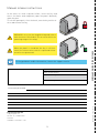
Manual release instructions
In the event of a fault or power failure, insert the key and
turn it clockwise and completely open the panel. Manually
open the gate.
To lock the gate again, close the hatch, turn the key anticlock-
wise and remove the key.
WARNING: carry out the wing blocking and release
with the motor switched off. Do not enter within the
operating range of the wing.
When the panel is closed but the key is still hori-
zontal, the release microswitch is open and all ma-
noeuvres are prevented.
Entrematic Group AB
Lodjursgatan 10
SE-261 44, Landskrona
Sweden
www.ditecentrematic.com

19
IP2160EN - 2013-10-31
All the rights concerning this material are the exclusive property of Entrematic Group AB.
Although the contents of this publication have been drawn up with the greatest care, Entrematic Group AB
cannot be held responsible in any way for any damage caused by mistakes or omissions in this publication.
We reserve the right to make changes without prior notice.
Copying, scanning and changing in any way are expressly forbidden unless authorised in writing by Entrematic
Group AB.

IP2160EN - 2013-10-31
Entrematic Group AB
Lodjursgatan 10
SE-261 44, Landskrona
Sweden
www.ditecentrematic.com
-
 1
1
-
 2
2
-
 3
3
-
 4
4
-
 5
5
-
 6
6
-
 7
7
-
 8
8
-
 9
9
-
 10
10
-
 11
11
-
 12
12
-
 13
13
-
 14
14
-
 15
15
-
 16
16
-
 17
17
-
 18
18
-
 19
19
-
 20
20


DITEC Ditec NES1000EHP Owner's manual
- Category
- Gate Opener
- Type
- Owner's manual
Ask a question and I''ll find the answer in the document
Finding information in a document is now easier with AI
Related papers
-
 DITEC CROSS18 Technical Manual
-
 DITEC Cross 18/19 User manual
-
 DITEC CROSS 18-19 Owner's manual
-
 DITEC OBBI Owner's manual
-
 DITEC DAS107 Technical Manual
-
 DITEC LUXO Owner's manual
-
 DITEC CROSS 3E Owner's manual
-
 DITEC CUBIC6TC Owner's manual
-
DITEC Ditec CROSS - IP1747 Owner's manual
-
 DITEC ALTA18 Owner's manual


Other documents
-
HQ VHS-C ADAPTOR Datasheet
-
Entrematic Ditec NeoS plus - IP2160 Owner's manual
-
 Entre Matic Ditec DAB205 User manual
-
Bauer CROSS3E Installation and Maintenance Manual
-
BFT Icaro Owner's manual
-
 Motostar ESC500 Usage And Maintenance Manual
-
 Ditec Entrematic CS12E User & Installation Manual
-
Proteco Matrix User manual
-
-


