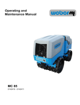
Wacker Neuson RT56-SC User manual

Category
Floor Machine
Type
User manual

This manual is also suitable for

www.wackergroup.com
Trench Roller
RT 56-SC
RT 82-SC
OPERATOR’S MANUAL
0154652en 014
0508
0154652EN
RT /... Table of Contents
wc_bo0154652012enTOC.fm 3
1. Foreword 5
2. Safety Information 6
2.1 Laws Pertaining to Spark Arresters ...................................................... 6
2.2 Operating Safety .................................................................................. 7
2.3 Operator Safety while using Internal Combustion Engines .................. 9
2.4 Service Safety .................................................................................... 10
2.5 Label Locations .................................................................................. 11
2.6 Warning and Informational Labels ...................................................... 12
3. Operation 16
3.1 Operation and Service Locations ....................................................... 16
3.2 Application .......................................................................................... 20
3.3 Control Features ................................................................................. 20
3.4 Accessing the Engine or Hydraulic Compartment .............................. 21
3.5 Accessing the Control Compartment .................................................. 21
3.6 Control Panel ...................................................................................... 22
3.7 SmartControl™ Transmitter ............................................................... 24
3.8 Infra-red System and Control Channels ............................................. 28
3.9 Before Starting ................................................................................... 30
3.10 Starting ............................................................................................... 31
3.11 Stopping ............................................................................................. 32
3.12 Operation ............................................................................................ 33
3.13 Position of Operator ........................................................................... 34
3.14 Range Limits ...................................................................................... 35
3.15 Operating Characteristics ................................................................... 36
3.16 Ni-Cad Battery .................................................................................... 36
3.17 Replacing the Battery Pack ................................................................ 36
3.18 Charging Transmitter Battery ............................................................. 37
3.19 Operation on Slopes ........................................................................... 39
3.20 Tip-overs and Roll-overs .................................................................... 40
3.21 Articulated Joint Locking Bar .............................................................. 40
Table of Contents RT /...
wc_bo0154652012enTOC.fm 4
4. Maintenance 42
4.1 Transporting Machine ..........................................................................42
4.2 Lifting Machine ....................................................................................42
4.3 Job Site Storage ..................................................................................43
4.4 Storage ................................................................................................44
4.5 New Machines .....................................................................................44
4.6 Periodic Maintenance Schedules ........................................................45
4.7 Hydraulic Oil Requirements .................................................................46
4.8 Hydraulic Oil Level ..............................................................................46
4.9 Changing Hydraulic Oil & Filter ...........................................................47
4.10 Articulated Joint, Steering Cylinder, and Hood Hinges .......................48
4.11 Cleaning SmartControl™ Transmitter .................................................48
4.12 Drive Gearcase ...................................................................................49
4.13 Exciter Lubrication ...............................................................................50
4.14 Scrapers ..............................................................................................51
4.15 Shockmounts .......................................................................................51
4.16 Changing Drums .................................................................................52
4.17 Battery .................................................................................................53
4.18 Engine Oil System ...............................................................................54
4.19 Engine Oil and Filter ............................................................................55
4.20 Air Cleaner ..........................................................................................56
4.21 Engine Fuel Delivery System Maintenance .........................................57
4.22 Fuel Filter ............................................................................................57
4.23 Priming the Fuel System .....................................................................58
4.24 Engine Coolant ....................................................................................58
4.25 Valve Clearances ................................................................................59
4.26 Adjusting Engine Fan Belt ...................................................................60
4.27 Basic Troubleshooting .........................................................................62
5. Technical Data 64
5.1 Engine .................................................................................................64
5.2 Roller ...................................................................................................65
5.3 Lubrication ...........................................................................................66
5.4 Sound and Vibration Measurements ...................................................66
5.5 Dimensions—0009025, 0009026, 0620365, 0620366, 0620397 ........67
5.6 Dimensions—0620324 ........................................................................67
5.7 Wiring Schematic—Machine Rev. 121 and lower ...............................68
5.8 Wiring Schematic—Machine Rev. 122 and higher ..............................70
wc_tx000001gb.fm 5
CALIFORNIA
Proposition 65 Warning:
Engine exhaust, some of its constituents, and certain vehicle
components, contain or emit chemicals known to the State of
California to cause cancer and birth defects or other reproductive
harm.
1. Foreword
This manual provides information and procedures to safely operate
and maintain this Wacker model. For your own safety and protection
from injury, carefully read, understand and observe the safety
instructions described in this manual.
Keep this manual or a copy of it with the machine. If you lose this
manual or need an additional copy, please contact Wacker
Corporation. This machine is built with user safety in mind; however,
it can present hazards if improperly operated and serviced. Follow
operating instructions carefully! If you have questions about operating
or servicing this equipment, please contact Wacker Corporation.
The information contained in this manual was based on machines in
production at the time of publication. Wacker Corporation reserves the
right to change any portion of this information without notice.
All rights, especially copying and distribution rights, are reserved.
Copyright 2007 by Wacker Corporation.
No part of this publication may be reproduced in any form or by any
means, electronic or mechanical, including photocopying, without
express written permission from Wacker Corporation.
Any type of reproduction or distribution not authorized by Wacker
Corporation represents an infringement of valid copyrights and will be
prosecuted. We expressly reserve the right to make technical
modifications, even without due notice, which aim at improving our
machines or their safety standards.
WARNING
Safety Information RT /...
wc_si000080gb.fm 6
2. Safety Information
This manual contains DANGER, WARNING, CAUTION, NOTICE and
NOTE callouts which must be followed to reduce the possibility of
personal injury, damage to the equipment, or improper service.
This is the safety alert symbol. It is used to alert you to potential
personal injury hazards. Obey all safety messages that follow this
symbol to avoid possible injury or death.
DANGER indicates a hazardous situation which, if not avoided, will
result in death or serious injury.
WARNING indicates a hazardous situation which, if not avoided, could
result in death or serious injury.
CAUTION indicates a hazardous situation which, if not avoided, could
result in minor or moderate injury.
NOTICE: Used without the safety alert symbol, NOTICE indicates a
hazardous situation which, if not avoided, could result in property
damage.
Note: Contains additional information important to a procedure.
2.1 Laws Pertaining to Spark Arresters
Notice: State Health Safety Codes and Public Resources Codes
specify that in certain locations spark arresters be used on internal
combustion engines that use hydrocarbon fuels. A spark arrester is a
device designed to prevent accidental discharge of sparks or flames
from the engine exhaust. Spark arresters are qualified and rated by
the United States Forest Service for this purpose.
In order to comply with local laws regarding spark arresters, consult
the engine distributor or the local Health and Safety Administrator.
DANGER
WARNING
CAUTION
RT /... Safety Information
wc_si000080gb.fm 7
2.2 Operating Safety
Familiarity and proper training are required for the safe operation of the
machine. Machines operated improperly or by untrained personnel
can be dangerous. Read the operating instructions contained in both
this manual and the engine manual and familiarize yourself with the
location and proper use of all controls. Inexperienced operators should
receive instruction from someone familiar with the machine before
being allowed to operate it.
2.2.1 ALWAYS operate machine with all safety devices and guards in place
and in working order. DO NOT modify or defeat safety devices. DO
NOT operate machine if any safety devices or guards are missing or
inoperative.
2.2.2 ALWAYS disengage and stow the locking bar for the articulated
steering joint before operating the machine. The machine cannot be
steered when the locking bar is engaged.
2.2.3 ALWAYS check that all controls are functioning properly immediately
after start-up! DO NOT operate machine unless all controls operate
correctly.
2.2.4 ALWAYS remain aware of changing positions and the movement of
other equipment and personnel on the job site.
2.2.5 ALWAYS remain in visual contact with machine at all times while
operating controls.
2.2.6 ALWAYS remain aware of changing surface conditions and use extra
care when operating over uneven ground, on hills, or over soft or
coarse material. The machine could shift or slide unexpectedly.
2.2.7 ALWAYS use caution when operating near the edges of pits, trenches
or platforms. Check to be sure that the ground surface is stable enough
to support the weight of the machine with the operator and that there
is no danger of the roller sliding, falling, or tipping.
2.2.8 ALWAYS position yourself safely when operating machine in reverse
or on hills. Leave enough space between yourself and the machine so
you will not be placed in a hazardous position should the machine slide
or tip.
2.2.9 ALWAYS use the SmartControl™ transmitter neck strap provided by
Wacker while operating with the control cable connected. This neck
strap is designed to break away so that the operator will not be
dragged by the machine should the machine slide, tip, or fall.
2.2.10 ALWAYS wear protective clothing appropriate to the job site when
operating equipment.
2.2.11 ALWAYS remain aware of moving parts and keep hands, feet, and
loose clothing away from the moving parts of the machine.
WARNING
Safety Information RT /...
wc_si000080gb.fm 8
2.2.12 ALWAYS read, understand, and follow procedures in the Operator’s
Manual before attempting to operate the equipment.
2.2.13 ALWAYS store the equipment properly when it is not being used.
Equipment should be stored in a clean, dry location out of the reach of
children.
2.2.14 NEVER allow anyone to operate this equipment without proper
training. People operating this equipment must be familiar with the
risks and hazards associated with it.
2.2.15 NEVER touch the engine or muffler while the engine is on or
immediately after it has been turned off. These areas get hot and may
cause burns.
2.2.16 NEVER use accessories or attachments that are not recommended by
Wacker. Damage to equipment and injury to the user may result.
2.2.17 NEVER leave machine running unattended.
2.2.18 NEVER start a defective unit in need of service or repair.
2.2.19 NEVER operate the machine with the fuel cap loose or missing.
2.2.20 NEVER operate multiple rollers within 14 meters (45 feet) of one
another, unless you are certain that each roller and its accompanying
transmitter have been set to a different control channel than the other
rollers/transmitters being used within the area. Refer to section Setting
Control Channels for additional information.
RT /... Safety Information
wc_si000080gb.fm 9
2.3 Operator Safety while using Internal Combustion Engines
Internal combustion engines present special hazards during operation
and fueling. Read and follow the warning instructions in the engine
owner’s manual and the safety guidelines below. Failure to follow the
warnings and safety guidelines could result in severe injury or death.
2.3.1 DO NOT run the machine indoors or in an enclosed area such as a
deep trench unless adequate ventilation, through such items as
exhaust fans or hoses, is provided. Exhaust gas from the engine
contains poisonous carbon monoxide gas; exposure to carbon
monoxide can cause loss of consciousness and may lead to death.
2.3.2 DO NOT smoke while operating the machine.
2.3.3 DO NOT smoke when refueling the engine.
2.3.4 DO NOT refuel a hot or running engine.
2.3.5 DO NOT refuel the engine near an open flame.
2.3.6 DO NOT spill fuel when refueling the engine.
2.3.7 DO NOT run the engine near open flames.
2.3.8 ALWAYS refill the fuel tank in a well-ventilated area.
2.3.9 ALWAYS replace the fuel tank cap after refueling.
2.3.10 ALWAYS check the fuel lines and the fuel tank for leaks and cracks
before starting the engine. Do not run the machine if fuel leaks are
present or the fuel lines are loose.
2.3.11 ALWAYS keep the area around a hot exhaust pipe free of debris to
reduce the chance of an accidental fire.
DANGER
Safety Information RT /...
wc_si000080gb.fm 10
2.4 Service Safety
Poorly maintained machines can become a safety hazard! In order for
the machine to operate safely and properly over a long period of time,
periodic maintenance and occasional repairs are necessary.
2.4.1 ALWAYS replace the safety devices and guards after repairs and
maintenance.
2.4.2 ALWAYS turn engine off and remove key from machine before
performing maintenance or making repairs. This is required to prevent
unintentional remote starting.
2.4.3 ALWAYS secure the articulated steering joint using the locking bar
before lifting, jacking, and servicing the machine. Machine halves
could swing together unexpectedly and cause a serious injury.
2.4.4 ALWAYS replace missing and hard-to-read labels. See Parts Manual
for ordering information.
2.4.5 ALWAYS make sure slings, chains, hooks, ramps, jacks and other
types of lifting devices are attached securely and have enough weight-
bearing capacity to lift or hold the machine safely. Always remain
aware of the location of other people around when lifting the machine.
2.4.6 ALWAYS keep the area around the muffler free of debris such as
leaves, paper, cartons, etc. A hot muffler could ignite the debris and
start a fire.
2.4.7 ALWAYS replace worn or damaged components with spare parts
designed and recommended by Wacker Corporation.
2.4.8 ALWAYS keep the machine clean and labels legible. Replace all
missing and hard-to-read labels. Labels provide important operating
instructions and warn of dangers and hazards.
2.4.9 DO NOT open hydraulic lines or loosen hydraulic connections while
the engine is running! Hydraulic fluid under pressure can penetrate the
skin, cause burns, blind, or create other potentially dangerous
hazards. Set all controls in neutral and turn engine off before loosening
the hydraulic lines.
2.4.10 DO NOT attempt to clean or service the machine while it is running.
Rotating parts can cause severe injury.
DO NOT use gasoline or other types of fuels or flammable solvents to
clean parts, especially in enclosed areas. Fumes from fuels and
solvents can become explosive.
2.4.11 DO NOT modify the machine without the express written approval of
the manufacturer.
2.4.12 DO NOT leave SmartControl™ transmitter unattended while servicing
machine.
WARNING
WARNING
RT /... Safety Information
wc_si000080gb.fm 11
2.4.13 ALWAYS turn the engine off before servicing the machine. If the
engine has electric start, disconnect the negative terminal on the
battery before servicing the machine.
2.5 Label Locations
T
Safety Information RT /...
wc_si000080gb.fm 12
2.6 Warning and Informational Labels
Wacker machines use international pictorial labels where needed.
These labels are described below:
Ref. Label Meaning
A WARNING!
Pressurized contents. Do not open
when hot!
B WARNING!
Hot surface!
C WARNING!
Pinch point
D Hydraulic oil reservoir fill tube.
E Radiator/Engine Oil
RADIATOR
KUEHLER
RADIADOR
RADIATEUR
ENGINE OIL
MOTOROEL
ACEITE DE MOTOR
HUILE À MOTEURS
wc_sy0154325
RT /... Safety Information
wc_si000080gb.fm 13
F DANGER!
Engines emit carbon monoxide; operate
only in well-ventilated area.
WARNING!
Read and understand the supplied
Operator’s Manual before operating the
machine. Failure to do so increases the
risk of injury to yourself or others.
WARNING!
To prevent hearing loss, wear hearing
protection when operating this machine.
G WARNING!
Infrared signal: Always aim transmitter
directly at receiving eye on machine.
1. No forward/reverse travel within 1
meter.
2. Machine may receive stray signals if
operated near solid objects.
H CAUTION!
Clean transmitter and receiving ele-
ments prior to operation.
Use only breakaway neck strap pro-
vided by Wacker to avoid possible oper-
ator injury.
I Operator’s Manual must be stored on
machine. Replacement Operator’s Man-
ual can be ordered through your local
Wacker distributor.
Ref. Label Meaning
Clean transmitter
and receiving
elements prior
to operation.
Use only breakaway neck strap
provided by Wacker to avoid
possible operator injury.
Nur den von Wacker ausgestatteten
ausloeseschultergurt verwenden,
um moegliche verletzung der
bedienungsperson zu vermeiden.
Solo use la correa al cuello
proporcionada por Wacker para
evitar posibles lesiones al
operador.
Utiliser seulement la bretelle
munie par Wacker pour eviter
blessures eventuelles a
L'utilisateur.
Vor Inbetriebnahme
Sendegerät
und Empfänger
reinigen.
Limpie el aparato
emisor-receptor
antes del
funcionamiento.
Nettoyer
l'émetteur et le
récepteur avant
l'opération.
CAUTION
VORSICHT
PRECAUCION
PRECAUTION
Safety Information RT /...
wc_si000080gb.fm 14
J WARNING!
Disconnect battery before servicing.
Read the Operator's Manual.
K Tie-down point.
L CAUTION!
Lifting point.
M A nameplate listing the model number,
item number, revision number, and
serial number is attached to each unit.
Please record the information found on
this plate so it will be available should
the nameplate become lost or dam-
aged. When ordering parts or request-
ing service information, you will always
be asked to specify the model number,
item number, revision number, and
serial number of the unit.
N This machine may be covered by one or
more patents.
Ref. Label Meaning
RT /... Safety Information
wc_si000080gb.fm 15
O Torque battery hold-down nuts to 3.5
Nm (2.5 ft.lbs.) max.
P CAUTION!
Engine oil may enter the cylinders if
machine tips over, causing possible
engine damage. Consult Operator’s
Manual or contact Wacker service
dealer for instructions before restarting.
Q Guaranteed sound power level in dB(A).
R WARNING!
Pinching hazard. Rotating machinery.
S CAUTION!
Do not stand within 1m (3ft) of the
machine when the amber control lights
are flashing. The roller will respond to
remote signals when the light is flash-
ing.
T Hydraulic oil drain.
Ref. Label Meaning
HYDRAULIC OIL
HYDRAULIKÖL
ACEITE HIDRÁULICO
HUILE HYDRAULIQUE
Operation RT /...
wc_tx000534gb.fm 16
3. Operation
3.1 Operation and Service Locations
See Graphic: wc_gr000234 and wc_gr000235
Ref. Description Ref. Description
1 Oil dipstick 25 Exciter fill plug
2 Engine oil drain plug 26 Exciter drain plug
3 Tie-down lugs 27 Exciter oil level plug
4 Air cleaner 28 Display panel
5 Scraper bar 29 SmartControl™ transmitter
6 Drive case fill plug 30 Charge cable
7 Drive case drain plug 31 Receiving eye/light ring
8 Drive case oil level plug 32 Oil cooler
9 Exciter pump 33 Docking port
10 Drive pump 34 Steering cylinder
11 Radiator 35 Decoder module
12 Hood latch 36 Engine control module
13 Lifting eye 37 Latch
14 Articulated joint locking bar 38 Manual holder
15 Hydraulic tank 39 Hood locking tab
16 Hydraulic tank return line filter 40 System fuse - 20A
17 Hydraulic oil level sight gauge 41 Self-resetting circuit breaker - 50A
18 Hydraulic tank drain plug 42 Charge cord / Service box recepta-
cle
19 Articulated joint grease fitting 43 Oil PSI switch
20 Steering cylinder grease fittings 44 Air filter restriction switch
21 Fuel tank - ---
22 Radiator drain plug 46 High water temperature switch /
Glow plug timer
23 Hydraulic manifold 47 Hood hinge grease fitting
24 Battery
RT /... Operation
wc_tx000534gb.fm 17
Operation RT /...
wc_tx000534gb.fm 18
Ref. Description Ref. Description
1 Oil dipstick 25 Exciter fill plug
2 Engine oil drain plug 26 Exciter drain plug
3 Tie-down lugs 27 Exciter oil level plug
4 Air cleaner 28 Display panel
5 Scraper bar 29 SmartControl™ transmitter
6 Drive case fill plug 30 Charge cable
7 Drive case drain plug 31 Receiving eye/light ring
8 Drive case oil level plug 32 Oil cooler
9 Exciter pump 33 Docking port
10 Drive pump 34 Steering cylinder
11 Radiator 35 Decoder module
12 Hood latch 36 Engine control module
13 Lifting eye 37 Latch
14 Articulated joint locking bar 38 Manual holder
15 Hydraulic tank 39 Hood locking tab
16 Hydraulic tank return line filter 40 System fuse - 20A
17 Hydraulic oil level sight gauge 41 Self-resetting circuit breaker - 50A
18 Hydraulic tank drain plug 42 Charge cord / Service box recepta-
cle
19 Articulated joint grease fitting 43 Oil PSI switch
20 Steering cylinder grease fittings 44 Air filter restriction switch
21 Fuel tank - ---
22 Radiator drain plug 46 High water temperature switch /
Glow plug timer
23 Hydraulic manifold 47 Hood hinge grease fitting
24 Battery
RT /... Operation
wc_tx000534gb.fm 19
Operation RT /...
wc_tx000534gb.fm 20
3.2 Application
This machine is designed for compaction of sub-bases and backfill for
foundations, roads, parking lots, etc. A selection of drum types, drum
sizes, and two vibration modes ensures excellent compaction of
cohesive-type soils. The drums protrude past the machine frame,
making it ideally suited for working along trench walls, excavations,
pipelines and backfill applications.
3.3 Control Features
See Graphic: wc_gr000957
This machine is designed specifically for remote control operation.
This feature protects the operator by allowing him or her to stand at a
distance from the machine, and the work area, during operation. When
used in excavations, it allows the operator to stand safely above the
trench, rather than in it.
The SmartControl™ transmitter (a) is designed for infra-red (IR)
remote-controlled operations only. The coil cord (b) is only used for
charging the transmitter battery or supplying power to the transmitter
when there is no battery. No control signals are sent through the cord.
The infra-red system includes the transmitter and two receiving eyes.
This system provides wireless line-of-sight operation up to 14 meters
(45 feet). It uses a hand-held transmitter to transmit signals to the
receiving eyes on the machine to control machine operation. Only one
eye needs to receive a signal for proper operation.
When operating multiple rollers within 14 meters (45 feet) of one
another, it is possible that the transmitter from one roller can
inadvertently take control of another roller. This can occur when
multiple rollers are set to the same control channel as that of one
transmitter. To prevent the transmitter from one roller inadvertently
taking control of another roller, be certain that each roller and its
accompanying transmitter are set to a different control channel than
the other rollers/transmitters being used within the area. Refer to
section Setting Control Channels for additional information.
a
b
wc_gr000957
  • Page 1 1
  • Page 2 2
  • Page 3 3
  • Page 4 4
  • Page 5 5
  • Page 6 6
  • Page 7 7
  • Page 8 8
  • Page 9 9
  • Page 10 10
  • Page 11 11
  • Page 12 12
  • Page 13 13
  • Page 14 14
  • Page 15 15
  • Page 16 16
  • Page 17 17
  • Page 18 18
  • Page 19 19
  • Page 20 20
  • Page 21 21
  • Page 22 22
  • Page 23 23
  • Page 24 24
  • Page 25 25
  • Page 26 26
  • Page 27 27
  • Page 28 28
  • Page 29 29
  • Page 30 30
  • Page 31 31
  • Page 32 32
  • Page 33 33
  • Page 34 34
  • Page 35 35
  • Page 36 36
  • Page 37 37
  • Page 38 38
  • Page 39 39
  • Page 40 40
  • Page 41 41
  • Page 42 42
  • Page 43 43
  • Page 44 44
  • Page 45 45
  • Page 46 46
  • Page 47 47
  • Page 48 48
  • Page 49 49
  • Page 50 50
  • Page 51 51
  • Page 52 52
  • Page 53 53
  • Page 54 54
  • Page 55 55
  • Page 56 56
  • Page 57 57
  • Page 58 58
  • Page 59 59
  • Page 60 60
  • Page 61 61
  • Page 62 62
  • Page 63 63
  • Page 64 64
  • Page 65 65
  • Page 66 66
  • Page 67 67
  • Page 68 68
  • Page 69 69
  • Page 70 70
  • Page 71 71
  • Page 72 72
  • Page 73 73
  • Page 74 74
  • Page 75 75
  • Page 76 76
  • Page 77 77
  • Page 78 78
  • Page 79 79
  • Page 80 80
  • Page 81 81
  • Page 82 82
  • Page 83 83
  • Page 84 84
  • Page 85 85
  • Page 86 86
  • Page 87 87
  • Page 88 88
  • Page 89 89
  • Page 90 90
  • Page 91 91
  • Page 92 92
  • Page 93 93
  • Page 94 94
  • Page 95 95
  • Page 96 96
  • Page 97 97
  • Page 98 98
  • Page 99 99
  • Page 100 100

Wacker Neuson RT56-SC User manual

Category
Floor Machine
Type
User manual
This manual is also suitable for

Ask a question and I''ll find the answer in the document

Finding information in a document is now easier with AI