Page is loading ...

PRECISION DIGITAL CORPORATION
89 October Hill Road • Holliston, MA 01746 USA
Tel (800) 343-1001 • Fax (508) 655-8990
www.predig.com
SNOOPER MODEL PD865
MODBUS
®
SERIAL INPUT
Instruction Manual
Modbus
®
RTU Master, Slave, or Snooper Mode
6-Digit Display, 0.56" (14 mm) High, Red LEDs, Sunlight Readable
Linear, Square Root, or Programmable Exponent
16-Point Linearization
Maximum/Minimum Display
Type 4X, NEMA 4X, IP65 Front
Universal Power Supply 85-265 VAC
12-36 VDC/12-24 VAC Power Option
2 or 4 Relays + 4-20 mA Output Options
24 VDC Transmitter Power Supply Option
RS-485 Serial Communications
Proxy Polling for up to 8 Process Variables

PD865 Snooper Modbus
Serial Input Meter Instruction Manual
2
Disclaimer
The information contained in this document is subject to change
without notice. Precision Digital makes no representations or
warranties with respect to the contents hereof; and specifically
disclaim any implied warranties of merchantability or fitness for a
particular purpose.
!
CAUTION: Read complete
instructions prior to
installation and operation
of the meter.
WARNING: Risk of
electric shock or
personal injury.
Warning
This product is not recommended for life support applications or
applications where malfunctioning could result in personal injury or
property loss. Anyone using this product for such applications does
so at his/her own risk. Precision Digital Corporation shall not be held
liable for damages resulting from such improper use.
Limited Warranty
Precision Digital Corporation warrants this product against defects in
material or workmanship for the specified period under
“Specifications” from the date of shipment from the factory. Precision
Digital’s liability under this limited warranty shall not exceed the
purchase value, repair, or replacement of the defective unit.
Registered Trademarks
All trademarks mentioned in this document are the property of their
respective owners.
©2010-2012 Precision Digital Corporation. All rights reserved.
www.predig.com

PD865 Snooper Modbus
Serial Input Meter Instruction Manual
3
Table of Contents
INTRODUCTION ------------------------------------------------------------------------------------ 6
ORDERING INFORMATION -------------------------------------------------------------------- 6
SPECIFICATIONS --------------------------------------------------------------------------------- 7
General ------------------------------------------------------------------------------- 7
Operating Modes ----------------------------------------------------------------- 8
Programmable Features for Master Mode -------------------------------- 9
Serial Communications --------------------------------------------------------- 9
Display Functions -------------------------------------------------------------- 10
Relays ------------------------------------------------------------------------------ 11
Isolated 4-20 mA Transmitter Output ------------------------------------ 12
COMPLIANCE INFORMATION -------------------------------------------------------------- 13
Safety ------------------------------------------------------------------------------- 13
SAFETY INFORMATION ----------------------------------------------------------------------- 13
INSTALLATION ----------------------------------------------------------------------------------- 14
Unpacking ------------------------------------------------------------------------- 14
Panel Mounting ------------------------------------------------------------------ 14
MOUNTING DIMENSIONS -------------------------------------------------------------------- 15
Connections ---------------------------------------------------------------------- 16
Connector Labeling ---------------------------------------------------------- 16
Power Connections ---------------------------------------------------------- 17
Serial Connections ----------------------------------------------------------- 18
Relay Connections ----------------------------------------------------------- 19
Switching Inductive Loads -------------------------------------------------- 19
4-20 mA Output Connections ---------------------------------------------- 21
SETUP AND PROGRAMMING --------------------------------------------------------------- 22
Front Panel Buttons and Status LED Indicators --------------------- 23
Display Functions and Messages ----------------------------------------- 24
Main Menu ------------------------------------------------------------------------ 29
Setting Numeric Values ------------------------------------------------------ 29
Meter Setup ----------------------------------------------------------------------- 30
Operating Modes (nmode) ---------------------------------------------------- 30
Master Mode (nmastr) ------------------------------------------------------ 31
Proxy Polling Mode ---------------------------------------------------------- 32
Slave Mode (Slave) --------------------------------------------------------- 34
Snooper Mode (Snoopr) ---------------------------------------------------- 35
Serial Communications (SEriAL) ----------------------------------------- 36
Program Menu (Prog) ------------------------------------------------------- 36
Setting the Display Decimal Point (disp..dp) --------------------------- 37

PD865 Snooper Modbus
Serial Input Meter Instruction Manual
4
Setting the Float Decimal Point (Flot..dp) ------------------------------ 37
Scaling the Display Value (scale) --------------------------------------- 38
Setting the Relay Operation (relay) ------------------------------------ 39
Relay and Alarm Operation ------------------------------------------------ 42
Scaling the 4-20 mA Analog Output (Aout) ---------------------------- 49
Setting Up the Password (pass) ------------------------------------------- 50
Locking the Meter ------------------------------------------------------------ 50
Unlocking the Meter ---------------------------------------------------------- 51
Advanced Features Menu ---------------------------------------------------- 52
Advanced Features Menu & Display Messages ---------------------- 53
Display Math Function (func) --------------------------------------------- 54
Noise Filter (filter) -------------------------------------------------------- 55
Noise Filter Bypass (bypass) ---------------------------------------------- 55
Low-Flow Cutoff (CutofF) -------------------------------------------------- 55
Analog Output Programming (aoutpr) ---------------------------------- 56
4-20 mA Output Calibration ------------------------------------------------ 57
Display Intensity (d-inty) -------------------------------------------------- 58
Information (info) ------------------------------------------------------------ 58
OPERATION --------------------------------------------------------------------------------------- 59
Master and Slave Connections -------------------------------------------- 59
Maximum/Minimum Readings ---------------------------------------------- 62
TROUBLESHOOTING -------------------------------------------------------------------------- 63
Determining Software Version --------------------------------------------- 63
Reset Meter to Factory Defaults ------------------------------------------- 63
Factory Defaults & User Settings ----------------------------------------- 64
Troubleshooting Tips --------------------------------------------------------- 68
SLAVE MODE REGISTER TABLE ---------------------------------------------------------- 69
Register Table Notes ---------------------------------------------------------- 79
Register Bit Assignment Tables ------------------------------------------- 81

PD865 Snooper Modbus
Serial Input Meter Instruction Manual
5
Table of Figures
Figure 1: Panel Cutout and Mounting ............................................... 14
Figure 2: Meter Dimensions – Side View .......................................... 15
Figure 3: Case Dimensions – Top View ............................................ 15
Figure 4: Connector Label: 4 Relays, 4-20 mA Out & 24 V Supply 16
Figure 5: Power Connections ............................................................ 17
Figure 6: RS-485 Connection ............................................................ 18
Figure 7: Standard and Optional Relay Connectors........................ 19
Figure 8: AC and DC Loads Protection ............................................ 19
Figure 9: Low Voltage DC Loads Protection .................................... 20
Figure 10: 4-20 mA Output Powered by Meter ................................. 21
Figure 11: 4-20 mA Output Powered Externally ............................... 21
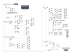
Figure 12: PD865 Slave & Snooper Connected to a Master ............ 59
Figure 13: PD865 Master Connected to a Smart Sensor & Chart
Recorder .............................................................................................. 59
Figure 14: PD865 Master Connected to a PD765 Meter ................... 60
Figure 15: PD865 Master & Snoopers Connected to Multivariable
Level Transmitters ............................................................................. 60
Figure 16: PD865 Master & Snoopers Connected to Level and
Temperature Sensors......................................................................... 61

PD865 Snooper Modbus
Serial Input Meter Instruction Manual
6
INTRODUCTION
The PD865 Snooper Modbus Serial Input Meter can be programmed as a
Modbus RTU Master, Slave, or Snooper. As a Master, the PD865 reads a
slave device, scales the data from it, displays the result, and operates the
internal relays and 4-20 mA output. The PD865 Master mode is capable of
polling up to 8 process variables (Proxy polling feature); it displays PV1 and
allows other PD865s in Snooper mode to read any of the variables being
polled by the Master. As a Slave, it is controlled by a master device. The
data sent to it by the master is scaled, displayed, and used to operate the
relays and 4-20 mA output. As a Snooper the PD865 listens to the Modbus
traffic and picks up a specific register or registers being polled by a Master
device from a specific slave device and processes the data being read.
The PD865 Snooper is housed in a shallow-depth 1/8 DIN panel meter
enclosure that features a NEMA 4X front panel. Data is displayed on an
adjustable intensity, six-digit seven-segment LED display. The Snooper can
be powered from 85-265 VAC or 12-36 VDC. It comes standard with 2
relays and is available with 2 additional relays and 4-20 mA output as
options.
ORDERING INFORMATION
85-265 VAC*
Model
12-36 VDC*
Model
Installed
PD865-6R2-06 2 relays
PD865-6R5-16
2 relays, 4-20 mA output/24 V
transmitter supply
PD865-6R7-16
4 relays, 4-20 mA output/24 V
transmitter supply
PD865-7R5-06 2 relays, 4-20 mA output
PD865-7R7-06 4 relays, 4-20 mA output
*All models may be powered from AC or DC. See Specifications for details.
Accessories
Model Description
PDA7485-I RS-232 to RS-422/485 Isolated Converter
PDA7485-N RS-232 to RS-422/485 Non-Isolated Converter
PDA8485-I USB to RS-422/485 Isolated Converter
PDA8485-N USB to RS-422/485 Non-Isolated Converter
PDX6901 Suppressor (snubber): 0.01 µF/470Ω, 250 VAC
Enclosures
NEMA 4 & explosion-proof enclosures**
Plastic, steel, stainless steel & cast aluminum
**Enclosures available for 1-10 meters. Visit our website for details.

PD865 Snooper Modbus
Serial Input Meter Instruction Manual
7
SPECIFICATIONS
Except where noted all specifications apply to operation at +25°C.
General
Input/Output Modbus RTU over RS-485
DISPLAY Six digits, 0.56" (14 mm) high, red LED. Displays from
-199999 to 999999, automatic leading zero blanking.
DISPLAY
UPDATE RATE
Master: 10/second to once every 25.5 seconds
Slave/Snooper: Dependent on master device (e.g. PLC)
OVERRANGE Values greater than the highest Input value programmed
cause the display to flash
999999
UNDERRANGE Values less than the Input 1 value cause the display to
flash
-199999
PROGRAMMING
METHODS
Four front panel buttons, or via Modbus registers.
RECALIBRATION Only required for the 4-20 mA output. Calibrated at the
factory. Recalibration is recommended at least every
12 months.
MAX/MIN
DISPLAY
Max/min readings are stored until reset by the user or
when power to the meter is turned off. User can reset by
front panel pushbuttons or via Modbus registers.
PASSWORD Programmable password restricts modification of
programmed settings.
NON-VOLATILE
MEMORY
All programmed settings are stored in non-volatile memory
for a minimum of ten years, with or without power.
POWER AC: 85-265 VAC, 50/60 Hz
DC: 90-265 VDC
Optional: 12-36 VDC, 12-24 VAC
Model Watts
PD865-6R2-06 6
PD865-6R5-16 8
PD865-6R7-16 15
PD865-7R5-06 10
PD865-7R7-06 10
REQUIRED FUSE
UL Recognized, 5 A max, slow-blow; up to 6 meters
may share one fuse.
ISOLATED
TRANSMITTER
POWER SUPPLY
One transmitter power supply (Optional)
24 VDC 10% @ 200 mA max. (-1 option)
ISOLATION 4 kV input/output-to-power line
500 V input-to-output or output-to-24 VDC supply

PD865 Snooper Modbus
Serial Input Meter Instruction Manual
8
ENVIRONMENTAL Operating temperature range: -40 to 65°C
Storage temperature range: -40 to 85°C
Relative humidity: 0 to 90% non-condensing
CONNECTIONS Removable screw terminal blocks accept 12 to 22 AWG
wire.
ENCLOSURE 1/8 DIN, high impact plastic,
UL 94V-0, color: gray
MOUNTING 1/8 DIN panel cutout required. Two panel mounting
bracket assemblies provided
TIGHTENING
TORQUE
Screw terminal connectors: 4.5 lb-in (0.5 Nm)
OVERALL
DIMENSIONS
2.45" x 4.68" x 4.19" (62 mm x 119 mm x 106 mm)
(H x W x D)
WEIGHT 8.0 oz (227 g) (2 relays)
9.7 oz (275 g) (4 relays, 4-20mA Output & 24 V supply)
WARRANTY 3 years parts and labor
Operating Modes
MASTER Processes data read from a Modbus RTU slave device
(only one process variable at a time can be displayed on
the master).
Proxy polling feature: Polls up to 8 process variables from
up to 8 slave devices. The Master processes and displays
PV1 and allows other PD865s in Snooper mode to read any
of the variables being polled.
SLAVE Processes data sent to it from a Modbus RTU master
device.
SNOOPER Listens to the Modbus traffic and picks up a specific register
or registers being polled by a Master device from a specific
slave device and processes the data being read.
Note: The relays and the 4-20 mA output are functional in
all modes.

PD865 Snooper Modbus
Serial Input Meter Instruction Manual
9
Programmable Features for Master Mode
FUNCTION CODE Select which Modbus function code (03 or 04) to use in
reading the slave device.
NUMBER
OF PVs
Select the number of process variables to be polled by the
Master (PV1-PV8).
SLAVE ID Assign the slave ID or address (1-247) containing the
process variables to be displayed (Slave ID for PV1-8).
REGISTER
NUMBER
5 digit: 30001-39999 or 40001-49999
6 digit: 300001-365536 or 400001-465536
Specifies which register(s) to read in the slave device.
Range is dependent on Function Code selection (04 or 03)
and digits selection (5 or 6).
PV2-PV8: Select 1 register for Short integer or 2 registers
for Long integer and Floating point data types.
DATA TYPE Select the data format that the slave device uses. Select
between Short integer (2 byte) and Long integer (4 byte) or
floating point (4 byte), Signed or Unsigned (integer only)
and byte order (big-endian vs. little-endian).
POLL TIME 0.1 to 25.5 sec. Time between read-commands (Master
mode) or listening-time window (Snooper mode).
SLAVE
RESPONSE
TIMEOUT
0 to 25.4 seconds X3 (76.2 sec). Time allowed for the slave
to respond to a command. Programming 0 disables the
timeout. This setting is used by Master and Slave modes.
Serial Communications
SLAVE ID
OR ADDRESS
1 – 247. Specifies the ID or address of the slave device
(Master or Snooper mode) or the address of the PD865
(Slave mode).
BAUD RATE 300 – 19,200 bps
DATA 8 bit (1 start bit, 1 or 2 stop bits)
PARITY None, even, or odd. 1 or 2 stop bits selectable for None.
BYTE-TO-BYTE
TIMEOUT
0.01 – 2.54 seconds
TURN AROUND
DELAY
Less than 2 ms (fixed)

PD865 Snooper Modbus
Serial Input Meter Instruction Manual
10
Display Functions
INTENSITY 1 to 8. To optimize viewing based on ambient lighting
conditions.
DISPLAY
DECIMAL POINT
Up to five decimal places:
d . ddddd, dd. dddd,
ddd . ddd,
dddd . dd, ddddd. d, or dddddd
FLOAT
DECIMAL POINT
Select the number of decimals to use for the floating point
data expected from the slave or master device (this is
independent from the display decimal point selection).
MATH
FUNCTIONS
Linear, square root, or programmable exponent (0.50000
to 2.99999).
MULTIPOINT
SCALING
2 to 16 points.
NOISE FILTER Programmable from 2 to 199 (0 will disable filter)
BYPASS 0.2 to 99.9% of full-scale.
CUTOFF
0 to 999999. 0 disables cutoff.

PD865 Snooper Modbus
Serial Input Meter Instruction Manual
11
Relays
RATING Standard: 2 relays, SPST (Form A)
Optional: 2 relays, SPDT (Form C)
All relays are rated 3 A @ 30 VDC or 3 A @ 250 VAC,
resistive loads.
ELECTRICAL
NOISE
SUPPRESSION
A suppressor (snubber) should be connected to each relay
contact switching inductive loads to prevent disruption to
the microprocessor’s operation. Recommended suppressor
value: 0.01 µF/470 , 250 VAC (PDX6901).
DEADBAND 0-100% of full scale, user selectable
HIGH OR LOW
ALARM
User may program any alarm for high or low trip point.
RELAY
OPERATION
Automatic (non-latching)
Latching
Pump alternation control (up to 4 relays)
RELAY RESET User selectable via front panel buttons or Modbus control
Automatic reset only (non-latching)
Automatic + manual reset at any time (non-latching)
Manual reset only, at any time (latching)
Manual reset only after alarm condition has cleared (latching)
Automatic reset: Relays will automatically reset when the
input passes the reset point.
Manual reset: Front panel ACK button. Pressing ACK
resets all manually resettable relays.
TIME DELAY 0 to 199 seconds, on and off delays
Programmable and independent for each relay
FAIL-SAFE
OPERATION
Programmable
Independent for each relay
COMMUNICA-
TIONS BREAK
No change, Relay on, or Relay off.
Controls the condition the relay goes to when a slave
device does not reply (Available also in Slave mode v1.1 &
up).
AUTO
INITIALIZATION
When power is applied to the meter, relays will reflect the
state of the input to the meter.
Fail-safe operation: relay coil is energized in non-alarm condition. In case of
power failure, relay will go to alarm state.

PD865 Snooper Modbus
Serial Input Meter Instruction Manual
12
Isolated 4-20 mA Transmitter Output
CALIBRATION Factory calibrated for 4-20 mA
SCALING RANGE 1.000 to 23.000 mA for any display range.
Reverse scaling allowed.
ACCURACY ± 0.1% F.S. ± 0.004 mA
TEMPERATURE
DRIFT
50 PPM/C from 0 to 65C ambient
EXTERNAL LOOP
POWER SUPPLY
35 VDC maximum
OUTPUT LOOP
RESISTANCE
Power supply Minimum Maximum
24 VDC
10 700
35 VDC (external)
100 1200
DATA
SOURCE
Display Value, Maximum Display Value, Minimum Display
Value, or Modbus Register.
OVERRANGE Programmable mA output for overrange condition.
UNDERRANGE Programmable mA output for underrange condition.
COMMUNICA-
TIONS BREAK
Programmable mA output when a slave device does not
reply within the Slave Response Timeout (Available also in
Slave mode v1.1 & up).
MAXIMUM
OUTPUT
Programmable absolute maximum mA output desired.
MINIMUM
OUTPUT
Programmable absolute minimum mA output desired.

PD865 Snooper Modbus
Serial Input Meter Instruction Manual
13
COMPLIANCE INFORMATION
Safety
UL LISTED USA and Canada
UL 508 Industrial Control Equipment
UL FILE NUMBER E160849
FRONT PANEL UL Type 4X, NEMA 4X, IP65; panel gasket provided
SAFETY INFORMATION
!
CAUTION: Read complete
instructions prior to
installation and operation
of the meter.
WARNING: Risk of
electric shock or
personal injury.
Warning!
Hazardous voltages exist within enclosure.
Installation and service should be performed only by
trained service personnel.

PD865 Snooper Modbus
Serial Input Meter Instruction Manual
14
INSTALLATION
There is no need to remove the meter from its case to
complete the installation, wiring, and setup of the meter.
Unpacking
Remove the meter from box. Inspect the packaging and
contents for damage. Report damages, if any, to the carrier.
If any part is missing or the meter malfunctions, please contact
your supplier or the factory for assistance.
Panel Mounting
Prepare a standard 1/8 DIN panel cutout – 3.622" x 1.772" (92 mm
x 45 mm). Refer to Figure 1 for more details.
Clearance: allow at least 4" (102 mm) behind the panel for wiring.
Panel thickness: 0.04" - 0.25" (1.0 mm - 6.4 mm).
Recommended minimum panel thickness to maintain Type 4X
rating: 0.06" (1.5 mm) steel panel, 0.16" (4.1 mm) plastic panel.
Remove the two mounting brackets provided with the meter (back-off
the two screws so that there is ¼" (6.4 mm) or less through the
bracket. Slide the bracket toward the front of the case and remove).
Insert meter into the panel cutout.
Install mounting brackets and tighten the screws against the panel.
To achieve a proper seal, tighten the mounting bracket screws
evenly until meter is snug to the panel along its short side. DO NOT
OVER TIGHTEN, as the rear of the panel may be damaged.
Figure 1: Panel Cutout and Mounting

PD865 Snooper Modbus
Serial Input Meter Instruction Manual
15
MOUNTING DIMENSIONS
865SideViewDim
Figure 2: Meter Dimensions – Side View
Figure 3: Case Dimensions – Top View

PD865 Snooper Modbus
Serial Input Meter Instruction Manual
16
Connections
All connections are made to removable screw terminal connectors
located at the rear of the meter.
!
Caution!
Use copper wire with 60°C or 60/75°C insulation
for all line voltage connections. Observe all
safety regulations. Electrical wiring should be
performed in accordance with all applicable
national, state, and local codes to prevent
damage to the meter and ensure personnel
safety.
Connector Labeling
The connectors’ label, affixed to the meter, shows the location of all
connectors available with requested configuration.
Figure 4: Connector Label: 4 Relays,
4-20 mA Out & 24 V Supply

PD865 Snooper Modbus
Serial Input Meter Instruction Manual
17
Power Connections
Power connections are made to a two-terminal connector labeled
POWER in Figure 2. The meter will operate regardless of DC polarity
connection. The + and - symbols are only a suggested wiring convention.
1
2
AC or DC
POWER
Recommended External
Fuse: 1 A, 250 V Slow Blow
POWER CONNECTOR
+-
Figure 5: Power Connections

PD865 Snooper Modbus
Serial Input Meter Instruction Manual
18
Serial Connections
The PD865 is connected to an RS-485 bus with up to 32 nodes. For
systems consisting of more than 32 nodes, RS-485 repeaters are
necessary. Wiring connections to the PD865 are made via the three
position screw terminal connector labeled RS-485. Please refer to the
EIA-485 standard for complete specifications for balanced digital multi-
point communications. The use of shielded twisted pair cable is
recommended to protect the data signals from electrical interference.
For long wire runs it is good practice to terminate the bus at both ends
with a resistor connected between D+ and D- that matches the
characteristic impedance of the cable. A typical termination resistor
value is 120 Ω.
RS-485 Connector
D+ D- G
1 2 3
Shield
Data +
Twisted-Pair
Data -
Common
Figure 6: RS-485 Connection
For point-to-point (non-multipoint) serial communications with RS-232
data communications equipment (e.g. a personal computer), an RS-232
to RS-485 converter (e.g. the Precision Digital PDA7485) is required.
When using the PDA7485, connect the PD865 according to the
PDA7485 wiring diagram for a two wire RS-485 application.

PD865 Snooper Modbus
Serial Input Meter Instruction Manual
19
Relay Connections
Connections to the two, standard Form A relays, are made to the
connector labeled RLY1 and RLY2. See Figure 5. Connections to the
two optional Form C relays are made to the six-terminal connector
labeled RELAY3 and RELAY4.
Figure 7: Standard and Optional Relay Connectors
Switching Inductive Loads
The use of suppressors (snubbers) is strongly recommended when switching
inductive loads to prevent disrupting the microprocessor’s operation. The
suppressors also prolong the life of the relay contacts. Suppression can be
obtained with resistor-capacitor (RC) networks assembled by the user or
purchased as complete assemblies. Refer to the following circuits for RC network
assembly and installation:
L
O
A
D
or
Figure 8: AC and DC Loads Protection
Choose R and C as follows:
R: 0.5 to 1 for each volt across the contacts.
C: 0.5 to 1 µF for each amp through closed contacts.
Notes:
1. Use capacitors rated for 250 VAC.
2. RC networks may affect load release time of solenoid loads. Check to
confirm proper operation.
3. Install the RC network at the meter's relay screw terminals. An RC network
may also be installed across the load. Experiment for best results.
4. For low voltage DC loads, place a diode across the load with a reverse
breakdown voltage two to three times the circuit voltage and a forward
current at least as large as the load current. Shown in
Figure 9

PD865 Snooper Modbus
Serial Input Meter Instruction Manual
20
L
O
A
D
Figure 9: Low Voltage DC Loads Protection
RC Networks Available from Precision Digital
RC networks are available from Precision Digital and should be applied to each
relay contact switching an inductive load. Part number: PDX6901.
Note:
Relays are de-rated to 1/14th HP (50 watts) with an inductive load.
/