Page is loading ...

To Parity
Page 1 of 3
mode
mastr
sLAve
Display:
Reading
Pass
Display:
Max Reading
Display:
Min Reading
Display:
New Max
Display:
New Min
When the meter is locked, parameters
can be viewed, but not changed.
unloC
Locked?
No
Yes
Locked?
No
Yes
loCd unloC
loCd
Lock
= 0000?
No
Yes
Correct
Lock?
No
Yes
Meter locks
Meter
unlocks
Invalid lock code:
Meter still locked
Menu or Enter pressed or
1 second timeout
Press MENU to exit or return
to Run Mode (Display
ProcessReading).
Meter is
still unlocked
NOTE: Pressing ENTER while displaying Max or Min will prevent the 10
second timeout from occurring. Pressing UP ARROW will still switch
between Max and Min and pressing RIGHT ARROW will still reset the Max or
Min to the present reading. Pressing MENU will stop this mode and return
back to displaying the Process Reading.
relay
FAiLSF
dElAY
rly n
Relay
Programming,
Page 2
After relay 4.
dlAy n
On n
Enter Relay n
On-Delay
Off n
Aout
fls n
User Entry:
On / Off
Menu pressed or
3 second timeout
Press Enter or
1 second timeout
loCd
funCod
10 second
timeout
rEgnbr
data
Float
Enter Register
Number
t-Poll
fun 03
fun 04
t-resp
Enter Polling
Rate
Enter Response
Timeout
addres
bAud
300
600
1200
2400
4800
9600
19200
paRiTY
No
Even
odd
t-bYt
serial
short
long
1234
4321
2143
3412
Unsigd
signed
Short?
Short
'n' is the relay number; 1 to 4. The dashed line
indicates that the menu cycles through all four
relay menus, then goes to Failsafe.
After relay 4.
Bcd
binary
For relays 1 to 3.
For Relays 1 to 3.
For relays 1 to 3.
dec pt
dd.dddd
ddd.ddd
dddddd
d.ddddd
dddd.dd
ddddd.d
prog
scale
To Scale
inp 1
dis 1
inp nn
dis nn
dis 1 out 1
dis 2 out 2
break breakn
User Entry:
none / On / Off
For relays 1 to 3.
After relay 4.
After relay 4.
Run Mode
Enter Modbus
Address
Enter Byte
Timeout
Enter
Input 1
Enter
Display 1
Enter
Input n
Enter
Display n
Enter
Display 1
Enter Relay n
Off-Delay
Enter
Display 2
Enter
mA Out 1
Enter
mA Out 2
Enter
Lock
unloC
Snooper PD865 Quick Start Guide
www.predig.com
www.predig.com
'nn' is the point number; 2 to 16. Only
the points specified by the Number
of Points (page 2) are shown.
PRECISION DIGITAL CORPORATION
19 Strathmore Road Natick MA 01760 USA
Tel (800) 343-1001 Fax (508) 655-8990
Press Up Arrow and Menu to enter
Quick Setpoints mode. This takes
you immediately to the relay set and
reset points menus.
Relay #1
Programming
Relay #2
Programming
To Display
Reading
Relay #3
Programming
Relay #4
Programming
ACKMAXRESETMENU
SR21
986599
43
SAve ?
Not Saved
Input
Data?
Bad:
Redundant or
Out of Order
Saved
Good
Error
FF--LL
'FF' is the first bad point number.
'LL' is the second bad point number.
1 stop
2 stop
5 dig
6 dig
5 second timeout

Factory Use Only!
Hold for 3 seconds to enter Advanced Features.
If locked, data can be displayed but not changed.
MENU exits & returns to Run Mode.
info
Software Version &
Manufacturing Serial
number display
To Display Reading
Relay
Programming
act n
Set n
rSt n
auto
LatCH
lt-Clr
altern
off
Auto
a-man
Enter
Setpoint
Enter
Resetpoint
Select
Auto
Select
Auto & Manual
Select
Latching -
Reset any time
Select
Latching - Reset
after condition
cleared
Select
Alternating
Pump
Select
Relay Off
*
*
*
Return to
appropriate
menu
* "n" is the relay number.
** If Locked, this is disabled, and values can only be displayed.
Any or all relays can be used in Alternating Pump mode.
Pressing MENU will exit.
Quick
Setpoint
= 1?
Yes
**
**
**
**
**
**
No
d-inty
Display is shown as
"int1" to "int8".
Func
linear
square
Prog e
no Pts
To Scale
(ScALE)
Selecting Square Root or Programmable
Exponent automatically sets the number of
scaling points to two (2). The Linear
function can have 2 to 16 scaling points.
bypass
filter
CutofF
Source
Disp
max
min
reg
O-rang
U-rang
max
min
Aoutpr
brEak
Slave?
Slave
NOTE: Press and hold RIGHT ARROW for 5 seconds while inFo is
displayed to enter Meter Reset Defaults mode (display shows rset.)
This is used to initialize the EEPROM to factory defaults. Press ENTER
to accept. Press MENU or no keys for 3 seconds to exit.
reset
Press and hold
for 5 seconds.
Default values are written to EEPROM.
Meter does a power-up reset.
To Display Reading
3 second timeout.
Calib
man
auto
NOTE: Requires a current loop connection with
a calibrated mA meter in the loop.
4 ma 20 ma
To: Display
Reading
Enter
Filter
Enter
Bypass
Enter
Cutoff
Enter
Exponent
Enter Number
of Pts
Enter
Overrange
Enter
Underrange
Enter
Comm. Break
Enter
Maximum
Enter
Minimum
Enter
Intensity
Enter 4 mA
reading
Enter 20 mA
reading
Relay Programming Submenu
Page 2 of 3
www.predig.com
Snooper PD865 Quick Start Guide
www.predig.com
PRECISION DIGITAL CORPORATION
19 Strathmore Road Natick MA 01760 USA
Tel (800) 343-1001 Fax (508) 655-8990
When the meter is locked, parameters
can be viewed, but not changed.
ACKMAXRESETMENU
SR21
986599
43
When the meter is locked,
Calibration is not available.

40001 –
40002
0 – 1
(0000–
0001)
Display
value
Read
Write
-199999 to
+999999
Long 03, 04, 16
Represents the display value without the decimal point. Decimal point
setting in 40013.
40003 –
40004
2 – 3
(0002–
0003)
Maximum
Display
value
Read
Write
-199999 to
+999999
Long 03, 04, 16
Represents the Maximum display value, excluding the decimal point,
since last power up or Max. Value reset. Decimal point setting in
40013. Writing any value will reset the max to the present display value.
40005 –
40006
4 – 5
(0004–
0005)
Minimum
Display
value
Read
Write
-199999 to
+999999
Long 03, 04, 16
Represents the Minimum display value, excluding the decimal point,
since last power up or Min. Value reset. Decimal point setting in 40013.
Can be written to any value between –199999 to +999999. Writing any
value will reset the max to the present display value.
Read alarm status and energized/non-energized status of relays.
Alarms are read only; the upper byte is ignored for writes. Writing to a
relay is only possible when the relay is in the Disabled mode.
Alm = Alarm. Rly = Relay.
15 - 12 11 10 9 8 7 - 4 3 2 1 0
40007
6
(0006)
Alarm and
Relay
Status
Read both,
Write
Relays
1 = In
Alarm
1 = relay
energized
Bits
03, 04,
06
0000
Alm
4
Alm
3
Alm
2
Alm
1
0000
Rly
4
Rly
3
Rly
2
Rly
1
Clear Relay n alarm condition. Set bit equal to 1 to acknowledge. Only
has effect on relays programmed to allow manual acknowledging.
Alm = Alarm.
15 - 12 11 10 9 8 7 - 4 3 - 0
40008
7
(0007)
Alarm
acknowled
ge
Write
Only
0x0000
to 0x0F00
Bits 06
0000
Alm
4
Alm
3
Alm
2
Alm
1
0000 0000
40009
8
(0008)
Initialize
meter
Write
Only
0xFF00 to
initialize.
Integer 06
Write 0xFF00 to reinitialize the meter. Writing any other data has no
effect.
40010
9
(0009)
Lock
Read
Write
0x0000 to
0x9999
Integer
(Packed
BCD)
03, 04, 06,
16
See note 4.
40011
10
(000A)
Mode
selection
Read
Write
Not
applicable
Word;
bit flags
03, 04, 06,
16
This Register is reserved for future use. Reading returns 0xffff and
writing to it has no effect.
40012
11
(000B)
Data Type
Read
Write
Not
applicable
Word;
bit flags
03, 04, 06,
16
This Register is reserved for future use. Reading returns 0xffff and
writing to it has no effect.
40013
12
(000C)
Decimal
Point
Read
Write
0 to 5 Integer
03, 04, 06,
16
See Bit Assignment Table 1.
40014
13
(000D)
Transfer
Function
Read
Write
0 to 2 Integer
03, 04, 06,
16
See Bit Assignment Table 2. Selecting Square Root or Exponent forces
Register 40015 (number of points) to be 2.
40015
14
(000E)
Number of
Points
Read
Write
2 to 16 Integer
03, 04, 06,
16
Number of scaling points. This cannot be changed if the Transfer
Function is set to Square Root or Exponent.
40016 –
40017
15 – 16
(000F –
0010)
Exponent
Read
Write
0.5 to
2.99999
Long 03, 04, 16 If Square Root is selected, this value is ignored.
40018
17
(0011)
Byte-to-
byte
timeout
Read
Write
0 to 2.54 Integer
03, 04, 06,
16
This is the timeout between bytes of a Modbus frame. It is
automatically changed to 1.5 * character time when the baud rate is
changed.
40019
18
(0012)
Slave
Response
Timeout
Read
Write
0 to 255 Integer
03, 04, 06,
16
Corresponds to 0.0 to 25.5 seconds. Not used in Slave mode.
40020
19
(0013)
Poll Time
Read
Write
1 to 255 Integer
03, 04, 06,
16
Corresponse to 0.1 to 25.5 seconds. 0 is not allowed. Polling time has
to be greater than or equal to slave response time. Master mode only.
40021
20
(0014)
LED
brightness
Read
Write
1 to 8 Integer
03, 04, 06,
16
8 is the brightest level.
40022
21
(0015)
Bypass
Read
Write
2 to 999 Integer
03, 04, 06,
16
Corresponds to 0.2 to 99.9%. If the input steps greater than the bypass
value, it will be displayed immediately, with no filtering occurring. The
number represents percent of full-scale. No effect if filter = 0.
40023
22
(0016)
Filter
Read
Write
0, 2 to 199 Integer
03, 04, 06,
16
Display filtering. 0 = no filtering.
New = old + ((new - old)/Filter)
40024 –
40025
23 – 24
(0017 –
0018)
Cutoff
Read
Write
0 to 999999 Long 03, 04, 16
Represents the display value without the decimal point. A value of
000000 disables the cutoff.
40026
25
(0019)
Serial
Settings
Read
Write
Not
applicable
Integer:
bits
03, 04, 06,
16
See Bit Assignment Table 3.
40027
26
(001A)
Unit
Address
Read
Write
1 to 247 Integer
03, 04, 06,
16
Master mode: the address of the slave being read.
Slave mode: the PD865’s address.
40101
To
40107
100 – 101
(0064 –
0065)
102 – 103
(0066 –
0067)
104 (0068)
105 (0069)
106 (006A)
Set-point
Reset-point
Turn-on
delay
Turn-off
delay
Mode
Read
Write
-199999 to
999999
(Set &
Reset)
0 to 199
0 to 199
Bits 4, 2, 1,
0
Long
Long
Integer
Integer
Word:
bits
03, 04, 16
03, 04,
06,16
Relay 1 parameters.
Set and reset points represent the display value without the decimal
point.
See Bit Assignment Table 4 for operating modes and bit assignments.
40108
To
40114
107 – 108
(006B –
006C)
109 – 110
(006D –
006E)
111 (006F)
112 (0070)
113 (0071)
Set-point
Reset-point
Turn-on
delay
Turn-off
delay
Mode
Read
Write
-199999 to
999999
(Set &
Reset)
0 to 199
0 to 199
Bits 4, 2, 1,
0
Long
Long
Integer
Integer
Word:
bits
03, 04, 16
03, 04,
06,16
Relay 2 parameters.
Set and reset points represent the display value without the decimal
point.
See Bit Assignment Table 4 for operating modes and bit assignments.
40115
To
40121
114 – 115
(0072 –
0073)
116 – 117
(0074 –
0075)
118 (0076)
119 (0077)
120 (0078)
Set-point
Reset-point
Turn-on
delay
Turn-off
delay
Mode
Read
Write
-199999 to
999999
(Set &
Reset)
0 to 199
0 to 199
Bits 4, 2, 1,
0
Long
Long
Integer
Integer
Word:
bits
03, 04, 16
03, 04,
06,16
Relay 3 parameters.
Set and reset points represent the display value without the decimal
point.
See Bit Assignment Table 4 for operating modes and bit assignments.
40122
To
40128
121 – 122
(0079 –
007A)
123 – 124
(007B –
007C)
125 (007D)
126 (007E)
127 (007F)
Set-point
Reset-point
Turn-on
delay
Turn-off
delay
Mode
Read
Write
-199999 to
999999
(Set &
Reset)
0 to 199
0 to 199
Bits 4, 2, 1,
0
Long
Long
Integer
Integer
Word:
bits
03, 04, 16
03, 04,
06,16
Relay 4 parameters.
Set and reset points represent the display value without the decimal
point.
See Bit Assignment Table 4 for operating modes and bit assignments.
40301
300
(012C)
4-20mA out
– Mode
Read
Write
Not
applicable
Integer:
bits
03, 04, 06,
16
Selects output option and where the data source for the 4-20mA
output. See Bit Assignment Table 5.
40302
301
(012D)
4-20mA out
–
Overrange
value
Read
Write
0 to 23999 Integer
03, 04, 06,
16
Corresponds to 0.000 to 23.999 mA. Because of hardware variations,
the actual output range is designed to be at least 1.000 to 23.000 mA.
40303
302
(012E)
4-20mA out
–
Underrang
e value
Read
Write
0 to 23999 Integer
03, 04, 06,
16
Corresponds to 0.000 to 23.999 mA. Because of hardware variations,
the actual output range is designed to be at least 1.000 to 23.000 mA.
40304
303
(012F)
4-20mA out
– Maximum
value
allowed
Read
Write
0 to 23999 Integer
03, 04, 06,
16
Corresponds to 0.000 to 23.999 mA. Because of hardware variations,
the actual output range is designed to be at least 1.000 to 23.000 mA.
40305
304
(0130)
4-20mA out
– Minimum
value
allowed
Read
Write
0 to 23999 Integer
03, 04, 06,
16
Corresponds to 0.000 to 23.999 mA. Because of hardware variations,
the actual output range is designed to be at least 1.000 to 23.000 mA.
40306
305
(0131)
4-20mA out
– Comm.
Break
value
Read
Write
0 to 23999 Integer
03, 04, 06,
16
Corresponds to 0.000 to 23.999 mA. Because of hardware variations,
the actual output range is designed to be at least 1.000 to 23.000 mA.
40307 –
40308
306 – 307
(0132 –
0133)
4-20mA out
– Display
Value 1
Read
Write
-199999 to
+999999
Long 03, 04, 16
4-20mA output scaling. Represents the display value without the
decimal point.
40309 –
40310
308 – 309
(0134 –
0135)
4-20mA out
– Display
Value 2
Read
Write
-199999 to
+999999
Long 03, 04, 16
4-20mA output scaling. Represents the display value without the
decimal point.
40311
310
(0136)
4-20mA out
– Output 1
Read
Write
0 to 23999 Integer
03, 04, 06,
16
4-20mA output scaling. mA output at Display Value 1.
40312
311
(0137)
4-20mA out
– Output 2
Read
Write
0 to 23999 Integer
03, 04, 06,
16
4-20mA output scaling. mA output at Display Value 2.
40313
312
(0138)
4-20mA out
– Data in
mA
or
Data in bits
Read
Write
0 to 23999
or
0 to 65535
Integer
03, 04, 06,
16
If 4-20mA output mode is set to “Serial Comm., mA” (0x83) this register
is in µA. Due to hardware variations, the actual output range is at least
1.000 to 23.000 mA.
If 4-20mA output mode is set to “Serial Comm., bits” (0x84), this
register is in DAC bits. See Bit Assignment Table 5.
40314 –
40315
313 – 314
(0139 –
013A)
4-20mA out
–
DAC
calibration:
Gain
Read
Write
Dependent
on
hardware.
Ideal =
2.85.
Float 03, 04, 16 4-20mA output gain calibration factor to convert mA to DAC counts.
40316 –
40317
315 – 316
(013B –
013C)
4-20mA out
–
DAC
calibration:
Offset
Read
Write
Dependent
on
hardware.
Ideal = 0.
Float 03, 04, 16 4-20mA output offset calibration factor to convert mA to DAC counts.
40401 –
40402
to
40431 –
40432
400 – 401
(0190 –
0191)
to
430 – 431
(01AE –
01AF)
Input 1
to
Input 16
Read
Write
-199999
to
999999
Long 03, 04, 16
Input values for the scaling of 2 to 16 data points.
Number of points set in Register 40015.
40433 –
40434
to
40463 –
40464
432 – 433
(01B0 –
01B1)
to
462 – 463
(01CE –
01CF)
Display 1
to
Display 16
Read
Write
-199999
to
999999
Long 03, 04, 16
Display values for the scaling of 2 to 16 data points.
Number of points set in Register 40015.
49101
To
49104
9100 –
9103
(238C –
238F)
Product
Identifier
Read
Only
Not
applicable
ASCII
charact
ers
03, 04 8 characters indicating the product firmware number
49105
To
49108
9104 –
9107
(2390 –
2393)
Firmware
Version
Read
Only
Not
applicable
ASCII
charact
ers
03, 04 8 characters indicating the firmware version number
49109
To
49116
9108 –
9115
(2394 –
239B)
Mfg. Serial
Number
Read
Only
Not
applicable
ASCII
charact
ers
03, 04
16 (max) characters indicating the manufacturing serial number
information.
Register
1
Number
Address
(hex)
Name Access
Limits
or
Range
2
Data
Type
3
Function
Code(s)
Comments
Register
1
Number
Address
(hex)
Name Access
Limits
or
Range
2
Data
Type
3
Function
Code(s)
Comments
Page 3 of 3
PRECISION DIGITAL CORPORATION
19 Strathmore Road Natick MA 01760 USA
Tel (800) 343-1001 Fax (508) 655-8990
www.predig.com
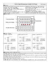
Slave Mode Register Tables
PD765 with
Modbus option
PD865 in
Master mode
RS-485
PDA7422
PD940
PD865 in Master
mode
RS-485
RS-485 to RS-232
Converter
RS-232
PDA7485 or similar
PD865 in Master
mode
Modbus-
capable
sensor
RS-485
PD940
PD865 in
Slave mode
Master
(PLC, DCS, etc)
RS-485
PD765 with
Modbus
option
Slave Slave
Snooper PD865 Typical Installation Diagrams
Snooper PD865 Quick Start Guide
www.predig.com
LIM865QS_A
SFT026 Ver 1.0 & up
03/05
PD865 (Slave mode) Connected to a Master
PD865 (Master mode) Connected to a Smart Sensor PD865 (Master mode) Connected to a PD940 PD865 (Master mode) Connected to a PD765
/