Baumer LXG-20M.3D Installation and Operating Instructions
- Category
- Security camera accessories
- Type
- Installation and Operating Instructions
This manual is also suitable for

Conformity / Safety
Further Information
For further information on our products visit www.baumer.com
For technical issues, please contact our technical support:
support.cameras@baumer.com · Phone +49 (0)3528 4386-0 · Fax +49 (0)3528 4386-86
© Baumer Optronic GmbH · Badstrasse 30 · DE-01454 Radeberg, Germany
Technical data has been fully checked, but accuracy of printed matter not guaranteed.
Subject to change without notice. Printed in Germany 04/17. v1.1 11185082
Conformity:
CE, RoHS
Safety Precautions
▪ Protect the sensor from dirt and
moisture.
▪ Never open the camera housing.
▪ Avoid camera contamination by
foreign objects.
Environmental requirements:
Storage temp. -10 °C ... +70 °C
Operating temp. +5 °C ... +50 °C
Housing temp. max. +50 °C
Humidity 10 % ... 90 %
Non-condensing
Quick Start Guide
LXG VisualApplets cameras for 3D Laser Triangulation
Latest software version and technical
documentation are available at:
www.baumer.com/vision/login
Product Specication
Integrated Center of Gravity (image preprocessing)
▪ Single Gigabit Ethernet progressive scan CMOS camera
▪ GigE Vision
®
standard compliant
▪ True partial scan function (ROI) for increased frame rates
▪ High Dynamic Range (HDR) image acquisition
▪ External synchronization via industrial compliant process interface (trigger / flash)
▪ Global shutter architecture for minimized motion blur
▪ Power over Ethernet (PoE) support
▪ Standard RJ45 connectors
▪ Excellent image quality
▪ Camera parameter programmable in real-time
▪ Integrated Center of Gavity (CoG) image preprocessing
Camera Type Sensor Size Resolution
Full Frames
1)
[max. fps]
Monochrome
LXG-20M.3D 2/3″ 2018 × 1088 338
LXG-120M.3D APS-C 4096 × 3072 60
1)
sensor frame rate
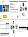
Dimensions Camera LXG-20M.3D
47
60
47
60
M58 x 0,75
Pixel 0,0
4 x M3 x 6
43,6
51,2
53,1
35,8
8
26
8 x M3 x 6
8
26
11,69±0,25
8
26
14,7
19,7
20
17,5
48,8
temperature
measurement point
14,7
Dimensions Camera LXG-120M.3D
47
60
47
60
M58 x 0,75
Pixel 0,0
4 x M3 x 6
44,75
52,35
54,25
35,8
8
26
8 x M3 x 6
8
26
12 ±0,25
8
26
14,7
19,7
20
17,5
48,8
14,7
Lens Adapter for LXG-20M.3D / LXG-120M.3D
▪ Adapter M58 / C-mount (Art. No: 11115198)
▪ Adapter M58 / C-mount (Scheimpug 2.5°) (Art. No: 11165019)
▪ Adapter M58 / M42x1-mount (26.8mm) (Art. No.: 11127232)
▪ Adapter M58 / M42x1-mount (45.5 mm) (Art. No.: 11137781)
Notice
suitable for Zeiss (e.g. Distagon T* 2/25 Z-M42-I, Planar T* 1.4/50 Z-M42-I,
Makro-Planar T* 2/50 Z-M42-I) and KOWA M42 lenses (e.g. LM28LF P-Mount,
LM35LF P-Mount)
▪ Adapter M58 / F-mount (Art. No.: 11117852)
CE
We declare, under our sole responsibility, that the
previously described Baumer LXG VisualApplets cameras
for 3D Laser Triangulation conform with the directives of
the CE.
RoHS
All LXG VisualApplets cameras for 3D Laser Triangulation
comply with the recommendation of the European Union
concerning RoHS Rules.

LED Signaling
LED
Signal Meaning
Camera
LED
green on Power on, link good
green blinking Power on, no link
red on Error
red blinking Warning (update in progress, don’t switch off)
yellow Readout active
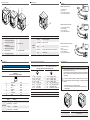
General Description
1
2
3
4
5
No. Description No. Description
1
LXG-20M.3D
lens mount (M58), adapter for
other lens mounts available
LXG-120M.3D
lens mount (M58), adapter for
other lens mounts available
4 Signaling-LED
2 Data Port 1 (PoE) 5 Digital-IO (RS485)
3 Power Supply / Digital-IO
Heat Transmission
Caution
Provide adequate dissipation of heat, to ensure that the temperature
does not exceed +50 °C (+122 °F).
The surface of the camera may be hot during operation and immediately
after use. Be careful when handling the camera and avoid contact over a
longer period.
As there are numerous possibilities for installation, Baumer do not speci-
y a specic method for proper heat dissipation, but suggest the following
principles:
▪ operate the cameras only in mounted condition
▪ mounting in combination with forced convection may provide proper
heat dissipation
T
T
Measure Point Maximal Temperature
T +50 °C (122 °F)
Data Interface
Notice
The Data port supports Power over Ethernet (36 VDC .. 57 VDC).
Data / Control
1000 Base-T
wire colors of the connecting cable
LED2
LED1
8
1
1 green/white MX1+
2 green MX1-
3 orange/white MX2+
4 blue MX3+
5 blue/white MX3-
6 orange MX2-
7 brown/white MX4+
8 brown MX4-
Signal Meaning
RJ45 LEDs
green on Link on
green blinking Link activity
amber on GigE speed
amber blinking 100 MB speed
Power Supply and Process Interfaces
Power and Process Interface #1
SACC-DSI-M8FS-8CON-M10-L180 SH
Power and Process Interface #2 (RS485)
SACC-DSI-M8MS-8CON-M8-L180 SH
M8 / 8 pins wire colors of the connecting cable
8
5
7
3
1
4
2
6
8
5
7
3
1
4
2
6
1 white OUT 3 (line 3) 1 white In2_RS485+ (line4)
2 brown Power VCC+ 2 brown In2_RS485- (line4)
3 green IN 1 (line 0) 3 green In2_RS485+ (line5)
4 yellow IO GND 4 yellow In2_RS485- (line5)
5 grey IO Power VCC 5 grey OUT3_In2_RS485+ (line6)
6 pink OUT 1 (line 1) 6 pink OUT3_In2_RS485- (line6)
7 blue Power GND 7 blue external Power GND
8 red OUT 2 (line 2) 8 red external Power 5 V/200 mA
Power Supply
Power VCC 12 VDC ... 24 VDC
Installation
open wire
4
Installation sample without PoE
1 - network interface card
2 - network cable
3 - Process interface- / Power cable
4 - Process interface cable (RS485)
open wire
4
open wire
4
5
Installation sample with PoE via NIC
1 - PoE network interface card (NIC)
2 - network cable (PoE)
3 - Process interface cable
4 - Process interface cable (RS485)
Installation sample with PoE via Injector
1 - network interface card (NIC)
2 - Injector
3 - network cable (with PoE)
4 - Process interface cable
5 - Process interface cable (RS485)
-
 1
1
-
 2
2


Baumer LXG-20M.3D Installation and Operating Instructions
- Category
- Security camera accessories
- Type
- Installation and Operating Instructions
- This manual is also suitable for
Ask a question and I''ll find the answer in the document
Finding information in a document is now easier with AI
Related papers
-
Baumer LXG-20M.PS Quick start guide
-
-
Baumer HXG40c Quick start guide
-
-
-
Baumer LXG-200C Quick start guide
-
-
-
-