Kenmore 41790802992 Installation guide

Category
Electric laundry dryers
Type
Installation guide
Before you begin ..................................................... 2
Location ................................................................... 2
Recommended grounding instructions .................... 2
Electrical requirements ............................................ 2
Exhaust requirements ............................................. 3
I
I
stalla
st ct
[]
|
Water supply and drain requirements ...................... 3
Please begin ............................................................ 3
Alternate installations .............................................. 5
Alternate methods of securing drain hose ............... 5
Alternate exhaust methods ...................................... 6
Alternate electrical connection ................................ 6
Rough-in dimensions ............................................... 8
Laundry Center
washer/dryer 240 volts
Sears, Roebuck and Co., Hoffman Estates, IL 60179 U.S.A.
P/N 131639100D (0503)
Before you begin...
Please read these instructions all the
way through.
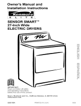
'_ screwdriver screwdriver
j 5ocket Level
A You need these tools to
install your Kenmore Laundry
® Center. Getthem together in
one place to keep track of
them.
B Check the where are
spot
you
going to install the Laundry
®Center. Proper installation is
your responsibility. Make
sure you have everything
necessary for proper
installation.
You will need to meet
State code/law requirements: Some
Codes keep from or limit installation of
clothes dryers in residential garages,
closets, mobile homes and sleeping
quarters. (Check with your local building
inspector.)
Important: Observe all governing
codes and ordinances.
Location
Size: Must be large enough to fully open
dryer door. For recessed or closet
installations see Page 5 for spacing; for
product dimensions see the last page of these
instructions.
Support: The floor must be able to support
the appliance loaded weight of 500 pounds.
Level Floor: Maximum floor slope under
Laundry Center is 1 inch.
Protection from the weather:
Proper operation of dryer cycles requires
temperatures above 45°F. As some water
remains in the washer, do not store or
operate the washer below 32°R For
storage below 32°F. see Use and Care
Guide for "Winterizing."
_ It is the personal responsibility of
the customer to ensure that gasoline,
paint, thinners and other flammable
materials are not used or stored near the
Laundry Center. Fumes from these
materials could result in fire, explosion
or personal injury.
_Never install the Laundry Center up
against draperies or curtains and be sure
to keep any and all items from failing or
collecting behind the Laundry Center.
_ Replace all access or service panels
before operating Laundry Center.
Recommended
grounding instructions
Electrical ground is required
on this appliance.
This appliance must be grounded. In the
event of malfunction or breakdown,
grounding will reduce the risk of electric
shock by providing a path of least
resistance for electric current.
Improper connection of
the equipment-grounding conductor
can result in a risk of electric shock. Check
with a qualified electrician or serviceman
if you are in doubt as to whether the
appliance is properly grounded.
Electrical requirements
1. A S-wire single phase 120/240 volt
60Hz AC only electrical supply (or 3-
wire 120/208 volt if specified on
nameplate) is required on a separate
30 ampere circuit, fused on both
sides of the line (time-delay fuse or
circuit breaker is recommended). Do
not have a fuse in the neutral or
ground circuit.
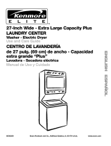
Ifa power supply cord is used, it must
be a 30 amp rated flexible type with
three open end spade lug connectors
with upturned ends or closed loop
terminal connectors. A U.h
recognized strain relief (U.L mark on
it or Sears Part No. 687000) to fit a
one inch hole must be used. When
local codes permit, it must be plugged
into a mating 30 amp receptacle
(NEMA) type 10-30R. See Figure 1.
Figure 1
3-wire receptacle
(10-30R)
The appliance may be connected
directly to the fused disconnect (or
circuit breaker) box through flexible
armored or nonmetallic sheathed 10
gauge COPPER cable, DO NOT USE
ALUMINUM WIRE. It is the personal
responsibility and obligation of the
customer to contact a qualified
installer to assure that the electrical
installation is adequate and is in
conformance with the National
Electrical Code and local codes and
ordinances. A U.L recognized strain
4.
relief must be provided at each end
of the power supply cable (at the
appliance and at the junction box).
Wire sizes (10 gauge COPPER WIRE
ONLY) and connection must conform
with the rating of the appliance (30
amperes).
DO NOT USE AN EXTENSION CORD.
For mobile home
installation, the appliance frame must
not be connected to the neutral
terminal, but must be connected to
the ground cord (see Page 6,
Alternate Electrical Connection, for
detailed instructions).
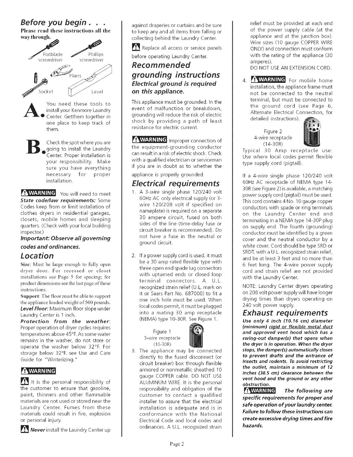
Figure 2
4-wire receptacle
(14-30R)
Typical 30 Amp receptacle use:
Use where local codes permit flexible
type supply cord (pigtail).
If a 4-wire single phase 120/240 volt
60Hz AC receptacle of NEMA type 14-
30R (see Figure 2) is available, a matching
power supply cord (pigtail) must be used.
This cord contains 4 No. 10 gauge copper
conductors with spade or ring terminals
on the Laundry Center end and
terminating in a NEMA type 14-30P plug
on supply end. The fourth (grounding)
conductor must be identified by a green
cover and the neutral conductor by a
white cover. Cord should be type SRD or
SRDT, with a U.L. recognized strain relief,
and be at least 3 feet and no more than
6 feet long. The 4-wire power supply
cord and strain relief are not provided
with the Laundry Center.
NOTE: Laundry Center dryers operating
on 208 volt power supply will have longer
drying times than dryers operating on
240 volt power supply.
Exhaust requirements
Use only 4 inch (10.16 cm) diameter
(minimum) rigid or flexible metal duct
and approved vent hood which has a
swing-out damper(s) that opens when
the dryer is in operation. When the dryer
stops, the damper(s) automatically closes
to prevent drafts and the entrance of
insects and rodents. To avoid restricting
the outlet, maintain a minimum of 12
inches (38.5 cm) clearance between the
vent hood and the ground or any other
obstruction.
The following are
specific requirements for proper and
safe operation of your laundry center.
Failure to follow these instructions can
create excessive drying times and fire
hazards.
Page 2
r,'_ Do not use plastic flexible
duct to exhaust the dryer. Excessive lint can
build up inside the exhaust system and create
a fire hazard and restrict air flow. Restricted
air flow will increase drying times, if your
present system is made up of plastic duct or
metal foil duct, re_lace it with a rigid or
flexible metal duct. Ensure the present duct
is free of any lint prior to installing laundry
center dryer duct.
_!_[[_ If the dryer is not
exhausted outdoors, some fine lintwill be
expelled into the laundry area. An
accumulation of lint in any area of the home
can create a health and fire hazard. The
dryer exhaust system MUST be
exhausted to the outside of the
dwelling!
_v'__ Do not allow
combustible materials (for example:
clothing,draperies/curtains, paper) to come
in contact with the exhaust system. The dryer
MUST NOT be exhausted into a chimney, a
wall, a ceiling, or any concealed space of a
building which can accumulate lint, resulting
in a fire hazard.
Do not exceed the
length of duct pipe or number of elbows
allowed in the" EXHAUST DUCT LENGTHS"
chart. Lint can accumulate in the system,
plugging the system and creating a fire
hazard, as well as increasing drying times.
Do not screen the
exhaust ends of the vent system, nor use
any screws or rivets to assemble the exhaust
_stem. Lint can become caught in the screen,
on the screws or rivets, clogging the exhaust
system and creating a fire hazard as well as
increasing drying times. Use an approved vent
hood to terminate the duct outdoors, and
seal all joints with duct tape. All male duct
pipe fittings MUST be installed downstream
with the flow of air.
Explosion hazard. Do
not install the laundry center where gasoline
or other flammables are kept or stored.If
the laundry center is installed in a garage, it
must be a minimum of 18 inches (45.7 cm)
above the floor. Failure to do so can result in
death, explosion, fire or burns.The exhaust
system back pressure MUST not exceed 0.6
inches (1.52 cm) of water column, measured
with an inclined manometer at the point
the exhaust connects to the dryer. The
exhaust system should be inspected and
cleaned a minimum of every two years with
normal usage. The more the dryer is used,
the more often you should check the
exhaust system and vent hood for proper
operation.
The Maximum Length of the exhaust
system depends upon the type of duct
used, number of elbows and type of
exhaust hood. The maximum length for
both rigid and flexible duct is shown in
chart.
EXHAUST DUCT LENGTHS (FEET)
EXHAUST HOOD TYPE
Numberof _ _ _
go° Turns
I I
4" LOUVERED 21/2"
MAXIMUM LENGTH OF 4-INCH DIAMETER
RIGID METAL DUCT
0 56' 56' 42'
1 46' 46' 36'
2 34' 34' 28'
3 32' 32' 18'
MAXIMUM LENGTH OF 4-INCH DIAMETER
FLEXIBLE METAL DUCT
0 30' 30' 22'
1 22' 22' 14'
2 16' 16' 10'
3 10' 10' 5'
Exhaust Systems longer than specified
will:
Shorten the life of the dryer.
Reduce the performance, such as
cause longer drying times and
increases the use of energy.
Accumulate lint.
The Laundry Center may be exhausted
four (4) ways with rear flush installation:
1. Straight back.
2. Down (8" length of 4" rigid duct
and1 elbow down).
3. Left (8" length of 4" rigid duct, 1
elbow down and 1 elbow left).
4. Right (8" length of 4" rigid duct, 1
elbow down and 1 elbow right).
To exhaust up, add an 11 " length of
standard 4" diameter duct and a 90°
elbow. The unit will be positioned about
4-1/2" away from the wall (flush to wall
exhausting may be done by going below
the dryer then sideways.)
An exhaust hood positioned to line up
with the dryer exhaust can be installed
directly through the outside wall. To
exhaust to the side or down, add an 8
inch (20.32 cm) length of standard 4 inch
(10.16 cm) diameter duct and a90° elbow.
For Mobile Home Exhaust
Requirements see Page 6, Alternate
Exhaust Methods, for detailed
instructions.
Water supply and drain
requirements
Hot and Coldwater faucets within 4 feet
of back of the Laundry Center and
enough pressure (5-100 PSI) are
required.
Water Heater should be set to deliver
130°F. or above water to the washer for
best results.
Todrain the Laundry Center washer, you
need either a 20-gallon laundry tub or
1-1/4 inch diameter standpipe having a
minimum carry-away capacity of 16
gallons per minute. The minimum tub
or standpipe height is 33 inches from
the bottom of the washer. The maximum
tub or standpipe height is 96 inches
from the bottom of the washer. For
installations requiring a longer drain
hose, have a qualified technician install
a longer hose, P/N 131461201. For drain
systems in the floor, install a siphon break
kit, P/N 076660-000. Both components
are available from Sears Parts
Department.
PLEASE BEGIN...
Remove:
(a) foam tub blocking pad;
® (b) foam shipping blocks
(c)
(d)
(e)
(f)
from rear of unit;
tape from dryer door;
foam dryer support pads;
inlet hoses.
From the back of the washer, remove
the wire shipping clips securing the
drain hose and power cord. Plastic
clamps secure the drain hose to the
right side of the washer backsheet.
These clamps form a standpipe to
prevent water siphoning. DO NOT
REMOVE THESE CLAMPS.
Page 3
Usingthe four shipping cartoncorner posts (two on each
side), carefully lay the
Laundry Center on its left side and
remove the foam shipping base.
Mechanisrn']_4_ _" _/
h,pping1
Shipping_g_ _
Pad _ __-'_
Shipping
Plastic Spacer Block Shipping Clips
Hose
Shipping Carton
Corner Posts
Usingtile ratchetwith 3/8 inch
socket, remove mechanism
shipping bolt. Removeplastic
spacer block from center of baseusing
adjustable pliers.
NOTE: If the Laundry Center isto be
transported at a later date, the tub
blocking pad,shipping bolt and plastic
spacer block should be retained.
__"_"_ Tub
_ _ _ _BJocking
Plastic_
Spacer _ Shipping
Block-_ b B°lt
Return Laundry Center to
upright position.
Install 3-wire power supply
cord.
® a. Removethe terminal block
cover located at the rear of the dryer.
b. Install U.L approved strain relief
(Figure11)in one inchhole on dryer
back below terminal block opening.
c. Thread U.L approved 30 amp
power cord through strain relief.
d. Connectthe centerwire ofthe power
cord to the center silver colored
terminal screwof the terminal block
and tighten securely.
e. Connectthe other wires to the outer
terminals and tighten securely
(Figure 12).
f. Replacethe terminal block cover.
Runsome water from tile hot
and cold faucets to flush the
water lines and remove
particles that might clog up the water
valve screens. Check inlet hoses to
ensurethe rubber washersare installed
in eachend. Carefully connect the inlet
hosesto the water valve(onthe left side
of the washercabinet),tighten byhand,
then tighten another 2/3 turn with
pliers.
DO NOT CROSS
THREAD OR OVERTIGHTEN
THESE CONNECTIONS.
Determinewhich water faucet
istile HOTwater faucet and
® carefullyconnectthe bottom
inlet hose to the HOT water faucet,
tighten by hand, then tighten another
2/3 turn with pliers. Carefully connect
the top inlet hose to the COLD water
faucet, tighten byhand, then tighten
another 2/3 turn with pliers.
DO NOT CROSS
THREAD OR OVERTIGHTEN
THESE CONNECTIONS.
Turntile water on and check for leaks
at both connections.
__"X
Form a "U" shapeon the end
of the drainhosewith the hose
pointed toward the drain.
Placethe formed end in a laundry tub
or astandpipe and securewith a cable
tie provided in the enclosure package.
WATER COIJLD
SIPHON FROM THE LAUNDRY
CENTER IF THE ABOVE
INSTRUCTIONS ARE NOT
FOLLOWED,
Carefully move the
laundry center to
its final location.
Plug the power cord into a
grounded outlet.
Page 4
0 To make sure the Laundry
Center is solid and level, tilt
the machine Ibrward so the
rear legs are offthe ground. Gently set
the machine back down to allow the
rear legs to self adjust. Place a level on
top of the washer. Check it side to side,
then front to back. Screw the front
leveling legs up or down to make sure
the unit is solid on all four legs (no
rocking of the appliance should exist).
i
1 Remove two (2) screws
securing front access panel
o to dryer cabinet. Lower
panel until bottom tabs can be
disengaged from cabinet, remove
panel, and set aside.
Access
Screws
Connect exhaust duct to
2 outside ductwork. Use duct
tape to seal all.joints. Do not
exceed the length of duct pipe or
number of elbows allowed in the
Maximum Length Chart, Page 3. Install
the exhaust duct as described in
Exhaust Requirements, Page 3, and
refer to the drawings below. To exhaust
inside, refer to Alternate Exhaust
Methods, Page 6.
CORRECT
INCORRECT INCORRECT
CORRECT
INCORRECT
L
h
INCORRECT
3 Read and save the Operat-
ing Instructions and the Use
and Care Guide that
came with the Laundry Center.
4 Clean the dryer drum and
washer tub with a damp
cloth.
5 Turn on electricity at power
source.
Start washer and dryer.
16 RUN THROUGH ONE
COMPLETE CYCLE and
check for possible leaks, exhaust con-
nections and tub drainage.
Reinstall access panel.
Alternate installations:
recessed or closet
area locations.
The following are minimum installa-
tion spacings and openings (in inches)
that you should allow. For easier
installation and service, consider
additional spacing.
Dryer
Wastner
Closet
Door
H
F
Side View
L
T
0
t_
F
_ r
Closet
Minimum Installation Spacing
RECESS
INSTALLATION A B C D F G H
INSIDE EXHAUST 4 0 4 0
OUTSIDE
EXHAUST 1 0 0 0
CLOSET
INSTALLATION A B C D F G H
OUTSIDE EXHAUST 60 60
ONLY I O 0 0 SQIR I SQIN
When the Laundry Center isinstalled
in other than the recessed and closet
type of installation shown, minimum
dimensionsindicatedmust beobserved.
To prevent large amounts of lint and
moisture from accumulating and to
maintain drying efficiency, this
appliance mustbe exhaustedoutdoors.
Non-exhausted installation-only rear
exhaust position permitted.
Alternate methods of
securing drain hose
Figure 3
Put the bent end of the
drain hose in the tub or
standpipe.
__able Tie
Thedrain hosemust beheld
securelywith the cabletie so
it does not come out
of the standpipe during use.
Cable
Tie
Figure 4
Page 5
C ecure the hose as shown
in Figures 3 Standpipe, 4
® Tub, 5 In wall standpipe.
FigUreCable5Tie _ ..........
BE SURE THE HOSE IS NOT
TWISTED OR KINKED AND IS
SECURELY IN PLACE.
Alternate Exhaust
Methods
There are exhaust kits
a available that allow you to
o direct filtered exhaust
air inside to conserve energy during
winter months. You may use these
deviceswith the Laundry Center dryer
providing their use does not violate
national or localcodes, and the device
does not restrictexhaust airflow. Ifyou
use one of these kits, be aware that
excessive moisture in the home can
causemany problemsand that you may
seean increase in the time required to
drya load.Also,you must maintain the
kit installation properly to avoid
excessivelint buildup, which can affect
the dryer's performance.
For mobile home installa-
B tion, the dryermust havean
o outside exhaust. If you
exhaustthe dryerthrough the floor and
the area under your mobile home is
enclosed, the exhaust system must
terminate outside the enclosed area.
Extension beyond the enclosure will
prevent lint and moisture buildup under
the mobile home. See Figure 7.
Mobile home installation
i!
Figure7
Alternate electrical
connection
Disconnect power supply cord from
electric supply before making these
changes.
Electrical ground is required on this
appliance.
This appliance is manufactured with the
neutral terminal connected to the frame.
A If local codes permit the use
of a flexible-type power
® supply cord (pigtail) and:
DO NOT permit connection of the
frame grounding conductor to the
neutral wire of the power supply
cord:
a. Remove terminal block cover.
b. Remove the ground wire from the
green ground screw and f_sten
under center silver-colored
terminal block screw. See Figure
8.
_-_€'I _ Ground clamp
"'"_)_T'_ attach to metal
cold water pipe
Ground wire _ ] Green
#10 mirfimurn f l jground
(not supplied)_[[
gmund_'_ \q V/ colored
wire ] ]![ screw
Ungrounded neutral
Figure 8
Connect separate copper ground wire
from green ground screw to approved
ground.
Connect a separate copper
ground wire (No. 10 minimum)
to a grounded cold water pipe*
by means of a clamp and then to
the frame of the appliance at the
green ground screw. Use Part
No. 685463 ground wire and
clamp assembly. Do not ground
to a gas supply pipe. Do not
connect the power supply cord
to electric power supply until
appliance is permanently
grounded.
d. Replace terminal block cover.
Page 6
Figure 9 Clam
Metal
Pipe
No. 4 Copper Wire
*Grounded cold water pipe must have
metal continuity to electrical ground and
not be interrupted by plastic, rubber or
other electrical insulating connectors
(such as hoses, fittings, washers or
gaskets, including water meter or pump).
Any electrical insulating connector
should be jumped as shown in Figure 9
with a length of No. 4 wire securely
clamped to barn metal at both ends.
B Local codes DO NOT permit
the use of a power supply
® cord and:
1. Permit connection of the frame
grounding conductor to the neutral
wire of the power supply cord:
a. Remove the terminal block
cover.
Terminal
Block --.
Figure 10
b. Install U.L. approved strain relief
(Figure 11) in one inch hole on
duet back below terminal block
opening.
Figure 11
c. Install copper power supply
cable.
d. Connecttheneutralwireofthe
flexiblearmoredornonmetallic
sheathedcopperpowersupply
cabletothecentersilver-colored
terminalscrewoftheterminal
blockandconnecttheotherwires
totheouterterminals.SeeFigure
12.Forconnectingplain-end
fieldwire,seeFigure15.
Replacetheterminalblockcover.
ground screw
\
Neutral
Grounded neutral
Figure 12
DO NOT permit connection of"the
frame grounding conductor to the
neutral wire of the power supply
cord:
a. Remove terminal block cover.
b. Install U.L. approved strain relief"
(Figure 11) in one inch hole on
dryer back below terminal block
opening.
c. Install copper power supply
cable.
d. Remove the ground wire from the
green ground screw and f_sten
under center silver-colored
terminal block screw.
e. Connect the neutral wire of the
power supply cable to the center
silver-colored terminal of the
terminal block and connect the
other wires to the outer terminals.
See Figure 13. For connecting
plain-end wire see Figure 15.
e.
Green
ground
wire
Green Ground Green Conductor
Screw , Silver Terminal
Terminal Block
Ground
Wire
Connect ,,round wire
from externalground connector to
approved ground.
Ungrounded neutral
Figure 13
fi Connect a separate copper
ground wire (No. 10 minimum)
to a grounded cold water pipe*
by means of a clamp and then to
the frame of the appliance at the
green ground screw. Use Part
No. 685463 ground wire and
clamp assembly. Do not ground
to a gas supply pipe. Do not
connect the power supply cord
to electric power supply until
appliance is permanently
grounded.
g. Replace the terminal block
cover.
*Grounded cold water pipe must have
metal continuity to electrical ground and
not be interrupted by plastic, rubber or
other electrical insulating connectors
(such as hoses, fittings, washers or
gaskets, including water meter orpump).
Any electrical insulating connector
should bejumped as shown in Figure 9
with a length of" No. 4 wire securely
clamped to bare metal at both ends.
If connecting to a four-
wire electrical system
® (mobile home):
1. Remove the terminal block cover.
2. Install U.L. approved strain relief
(Figure 11) in one inch hole on duer
back below terminal block opening.
3, Install copper 4-wire power supply
cord.
Remove the ground wire from the
green ground screw and fasten
under center silver-colored terminal
block screw.
5. Connect the ground wire (green) of"
the copper 4-wire power supply cord
to the green ground screw.
Connect the neutral wire (white) of
the power supply cord to the center
silver-colored terminal screw of the
terminal block and connect the other
wires to the outer terminals. See
Figure 14. For connecting plain-end
field wire, see Figure 15.
7, Replace the terminal block cover.
Page 7
Green Ground
Screw Green
Conductor
Silver Terminal
Terminal
Block
Ground
Wire
Red White Black
4-wire ungrounded neutral
Figure 14
IF YOUR POWER SUPPLY CORD
OR DIRECT WIRING HAS PLAIN
WIRE ENDS, SEE FIGURE 15 AND
FOLLOW THESE STEPS:
1. Strip outer covering back 3 inches
from the end exposing the 3 wires.
2. Strip the insulation back 1 inch from
the end of each wire. Form the bare
wire into a U-shaped hook.
3. Loosen, do not remove, the center,
silver-colored screw of the terminal
block.
4. Slide the end of the neutral (white
or center) wire under the screw head
with the open side of"the hook on
the right. Squeeze the wire together
to form a loop.
5. Tighten the screw firmly.
6. Connect the remaining 2 wires to the
outer screws the same way. Tighten
the screws firmly.
)
Ground
Green Ground Screw
Wire "_ "Neutral
Plain-end field wiring
Figure 15
ROUGH-IN D_MENSIONS
75 112"
54 5116"
0
"b
WATER INLETS
(REAR)
I
_ 3 3/4_
27"
16 1/4"
"i_''_ 41 114"
29 7116"
25 1/4"
T
...............30 13/16 ..... "_
2 W2_
4 13!16"
tl 7116"
Sears, Roebuck and Co.
Hoffman Estates, IL 60179 U°S.A.
Made in U.S.A.
75 t/2"
D_MENS+ONES PARA LA +NSTALACJON
54 /!6"
+
8
ESCAPE .......
EN]+RADA DEL AGUA
(PARTE TRASERA)
+
3 314"
-- 41 1!4"
29 71!6"
16 114"
/
/ 519
36 It!6"
Sears, Roebuck and Co,
Hoffman Estates+ +L60179 U°S,A,
T
q
2 tl2"
I
_J
30 !3116 ....... -=--_
4 13116"
11 7t16"
Fabricado en Jos EE.UU.
  • Page 1 1
  • Page 2 2
  • Page 3 3
  • Page 4 4
  • Page 5 5
  • Page 6 6
  • Page 7 7
  • Page 8 8
  • Page 9 9
  • Page 10 10
  • Page 11 11
  • Page 12 12
  • Page 13 13
  • Page 14 14
  • Page 15 15
  • Page 16 16

Kenmore 41790802992 Installation guide

Category
Electric laundry dryers
Type
Installation guide

Ask a question and I''ll find the answer in the document

Finding information in a document is now easier with AI

in other languages