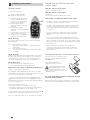
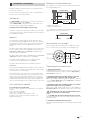
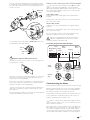
Truma Mover TE R is a maneuvering system that allows you to move your caravan without a towing vehicle. It consists of two separate drive units, each with a 12 Volt DC motor, which are attached to the frame of the vehicle near the wheels. Once the drive rollers have been engaged to the tires, you can operate the Mover using a remote hand set, which transmits radio signals to the control unit. The Mover is suitable for dual-axle caravans with a gross weight of up to 2250 kg on a suitable surface and can overcome inclines of up to 10%.
Truma Mover TE R is a maneuvering system that allows you to move your caravan without a towing vehicle. It consists of two separate drive units, each with a 12 Volt DC motor, which are attached to the frame of the vehicle near the wheels. Once the drive rollers have been engaged to the tires, you can operate the Mover using a remote hand set, which transmits radio signals to the control unit. The Mover is suitable for dual-axle caravans with a gross weight of up to 2250 kg on a suitable surface and can overcome inclines of up to 10%.


-
 1
1
-
 2
2
-
 3
3
-
 4
4
-
 5
5
-
 6
6
-
 7
7
-
 8
8
-
 9
9
-
 10
10


Truma Mover TE R User manual
- Type
- User manual
- This manual is also suitable for
Truma Mover TE R is a maneuvering system that allows you to move your caravan without a towing vehicle. It consists of two separate drive units, each with a 12 Volt DC motor, which are attached to the frame of the vehicle near the wheels. Once the drive rollers have been engaged to the tires, you can operate the Mover using a remote hand set, which transmits radio signals to the control unit. The Mover is suitable for dual-axle caravans with a gross weight of up to 2250 kg on a suitable surface and can overcome inclines of up to 10%.
Ask a question and I''ll find the answer in the document
Finding information in a document is now easier with AI
Related papers
-
Truma 60031 Mover SX Device User manual
-
-
-
-
-
-
-
-
-
Trumatic Ultraheat Solo Owner's manual
Other documents
-
 Truma Mover Caravan Mover 2 Owner's manual
-
EGO EGO300 User manual
-
SWIFT Caravan Owner's Handbook Manual
-
Hobby IC LINE Operating instructions
-
 Lunar Caravans User manual
-
 Hymer Familia 310 GT - 2004 Owner's manual
-
Bailey Caravan Owner's manual
-
LEISUREWIZE emove EM303 User manual
-
Adria Caravan User manual
-


