
(English)
Dealer's Manual
ROAD MTB Trekking
City Touring/
Comfort Bike
URBAN SPORT E-BIKE
Rear Derailleur
XTR
RD-M9100
RD-M9120
DEORE XT
RD-M8100
RD-M8120
RD-M8130
SLX
RD-M7100
RD-M7120
DEORE
RD-M6100
RD-M5100
RD-M5130
DM-MARD001-04

2
Contents
Contents ...................................................................................2
IMPORTANT NOTICE ..................................................................4
TO ENSURE SAFETY ...................................................................5
Cautions regarding LINKGLIDE 11-speed specifications .......7
List of tools to be used ............................................................9
Installation/removal ..............................................................10
Installing the rear derailleur ................................................................10
Adjustment .............................................................................12
Adjusting the stroke on the high limit ...............................................12
Installing the chain ...............................................................................12
Checking the chain length ...................................................................13
Connection and securing of the inner cable ......................................17
• Outer casing length ................................................................................................................ 17
• Connection and securing of the inner cable ........................................................................ 19
Adjusting the stroke on the low limit ................................................22
Adjusting the B-screw ..........................................................................23
SIS adjustment ......................................................................................25
Maintenance ...........................................................................27
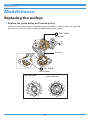
Replacing the pulleys ...........................................................................27
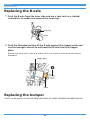
Replacing the B-axle ............................................................................28
Replacing the bumper ..........................................................................28
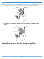
Applying grease to the chain stabilizer ..............................................29
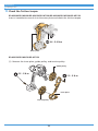
Adjusting friction .................................................................................31
• Friction adjustment ................................................................................................................ 32
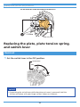
Replacing the plate, plate tension spring, and switch lever .............35


4
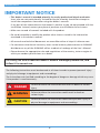
IMPORTANT NOTICE
IMPORTANT NOTICE
• This dealer's manual is intended primarily for use by professional bicycle mechanics.
Users who are not professionally trained for bicycle assembly should not attempt to
install the components themselves using the dealer's manuals.
If any part of the information on the manual is unclear to you, do not proceed with the
installation. Instead, contact your place of purchase or a distributor for assistance.
• Make sure to read all manuals included with the product.
• Do not disassemble or modify the product other than as stated in the information
contained in this dealer's manual.
• All manuals and technical documents are accessible online at https://si.shimano.com.
• For consumers who do not have easy access to the internet, please contact a SHIMANO
distributor or any of the SHIMANO offices to obtain a hardcopy of the User's Manual.
• Please observe the appropriate rules and regulations of the country, state or region in
which you conduct your business as a dealer.
For safety, be sure to read this dealer's manual thoroughly before use, and
follow it for correct use.
The following instructions must be observed at all times in order to prevent personal injury
and physical damage to equipment and surroundings.
The instructions are classified according to the degree of danger or damage which may occur
if the product is used incorrectly.
DANGER
Failure to follow the instructions will result in death or serious
injury.
WARNING
Failure to follow the instructions could result in death or
serious injury.
CAUTION
Failure to follow the instructions could cause personal injury or
physical damage to equipment and surroundings.

5
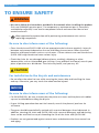
TO ENSURE SAFETY
TO ENSURE SAFETY
WARNING
• Be sure to follow the instructions provided in the manuals when installing the product.
Only use SHIMANO genuine parts. If a component or replacement part is incorrectly
assembled or adjusted, it can lead to component failure and cause the rider to lose
control and crash.
•
Wear approved eye protection while performing maintenance tasks such as
replacing components.
Be sure to also inform users of the following:
• Clean the chain and QUICK-LINK with an appropriate chain cleaner regularly. Intervals
between maintenance depend on the use and riding circumstances. Never use alkali
based or acid based solvents such as rust cleaners. If those solvents are used the chain or
QUICK-LINK might break and cause serious injury.
• Check the chain for any damage (deformation or cracking), skipping, or other
abnormalities such as unintended gear shifting. If any problems are found, consult your
place of purchase or a distributor. The chain may break, and you may fall.
CAUTION
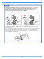
For installation to the bicycle and maintenance
• Do not allow the wheel to turn while securing the inner cable and installing the inner
end cap. Otherwise, you may touch the wheel and be injured.
NOTICE
Be sure to also inform users of the following:
• For SHADOW RD+, be sure to check that the plate unit cover and the plate unit rubber
cap are installed before riding the bicycle.
• If gear shifting operation does not feel smooth, consult the place of purchase for
assistance.
• The gears should be periodically washed with a neutral detergent then lubricated. In
addition, cleaning the chain and QUICK-LINK with a neutral detergent and lubricating
them can be an effective way of extending the life of the chain and QUICK-LINK.
• Products are not guaranteed against natural wear and deterioration from normal use
and aging.

6
TO ENSURE SAFETY
• For maximum performance we highly recommend SHIMANO lubricants and maintenance
products.
For installation to the bicycle and maintenance
• Depending on the shape of the frame, the rear derailleur may interfere with the
chainstay.
• Grease with SIS SP41 grease (Y04180000) the inner cable and the sliding portions of the
outer casing before use to ensure that they slide properly. Do not let dust adhere to the
inner cable.
• Use an OT-SP41 outer casing and a cable guide for smooth operation.
• Use an outer casing which still has some length to spare even when the handlebars are
turned all the way to either side. Furthermore, check that the shifting lever does not
touch the bicycle frame when the handlebars are turned all the way.
• If gear shifting adjustments cannot be carried out, check the alignment of the dropout
and check if the cable is lubricated or if the outer casing is too long or too short.
• Periodically clean the shifting unit and lubricate all moving parts (mechanism and
pulleys).
• Note the installation direction of the pulleys. Depending on the model, the pulley has
arrows on it to indicate the direction of rotation. Install the pulley so that the arrows are
pointing counterclockwise when looking at the outer side of the shifting unit.
• If you hear abnormal noise as a result of excess play in a pulley, you should replace the
pulley.
• Before using RD-M8130/RD-M5130 and other LINKGLIDE products, check the
combinations listed in the compatibility information (https://productinfo.shimano.com/#/
com). Other products cannot be used because the specifications do not match.
11-speed specifications: https://productinfo.shimano.com/#/com?cid=C-432&acid=C-435
10-speed specifications: https://productinfo.shimano.com/#/com?cid=C-432&acid=C-436
The actual product may differ from the illustration because this manual is
intended mainly to explain the procedures for using the product.

7
Cautions regarding LINKGLIDE 11-speed specifications
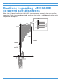
Cautions regarding LINKGLIDE
11-speed specifications
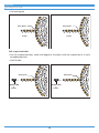
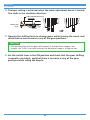
When using 11-speed specification LINKGLIDE, interference may occur with the rear derailleur
and spokes. Check dimensions beforehand, and check that points A and B do not interfere with
the spokes or other parts.
X
Point A
Point B
71 mm
124 mm
5.25 mm
10 mm
Y
X
Y

8
Cautions regarding LINKGLIDE 11-speed specifications
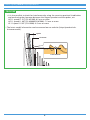
TECH TIPS
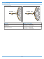
• It is also possible to check for interference by using the cassette sprockets listed below
and measuring the clearance between the largest sprocket and the spokes, etc.
HG 11-speed 11-51T (CS-M5100): 8.5 mm or more
HG 11-speed 11-46T (CS-M8000/CS-M7000): 7.5 mm or more
LG 11-speed 11-50T (CS-LG600): 6.5 mm or more
* The latest model information can be accessed on our website (https://productinfo.
shimano.com/#/).
Tooth bottom
Spoke
Clearance

9
List of tools to be used
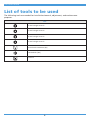
List of tools to be used
The following tools are needed for installation/removal, adjustment, and maintenance
purposes.
Tool
2 mm hexagon wrench
3 mm hexagon wrench
4 mm hexagon wrench
5 mm hexagon wrench
Cross head screwdriver [#2]
Hexalobular [#27]
TL-CT12

10
Installation/removal
Installing the rear derailleur
Installation/removal
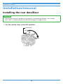
Installing the rear derailleur
TECH TIPS
• The rear derailleur will not gear shift properly if the derailleur hanger is not straight.
Use TL-RD11 to check whether the derailleur hanger is straight or not.
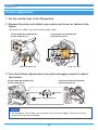
1. Set the switch lever in the OFF position.
ON
Switch lever
OFF

11
Installation/removal
Installing the rear derailleur
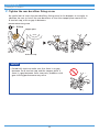
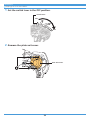
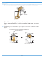
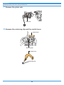
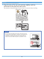
2. Tighten the rear derailleur fixing screw.
Be careful not to insert the rear derailleur fixing screw in the dropout at an angle. In
addition, be sure to install the rear derailleur so that the stopper plate contacts the
B-tension stop, with no gap in between.
Rear derailleur fixing screw
Stopper plate
B-tension stop
8 - 10 N·m
NOTICE
• Periodically check to make sure that there is no gap
between the B-tension stop and the stopper plate. If
there is a gap between these two parts, problems with
gear shifting performance may occur.

12
Adjustment
Adjusting the stroke on the high limit
Adjustment
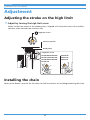
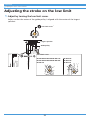
Adjusting the stroke on the high limit
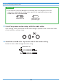
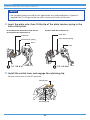
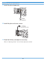
1. Adjust by turning the high limit screw.
Adjust so that the center of the guide pulley is aligned with the outer face of the smallest
sprocket when viewed from the rear side.
High limit screw *
Smallest sprocket
Guide pulley
*High limit screw
RD-M9100/RD-M8100/
RD-M8130/RD-M7100/
RD-M6100/RD-M5100/
RD-M5130
RD-M9120/
RD-M8120/
RD-M7120
Installing the chain
Refer to the dealer's manual for the chain to find instructions on installing/removing the chain.

13
Adjustment
Checking the chain length
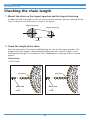
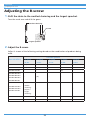
Checking the chain length
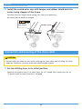
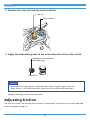
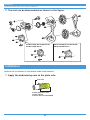
1. Mount the chain on the largest sprocket and the largest chainring.
In order to check the length at the rear of the cassette sprocket, join the two ends of the
chain at the rear of the cassette as shown in the figure.
Largest sprocket
Largest chainring
Chain
2. Check the length of the chain.
With the zero point of the chain established on the rear of the largest sprocket, the
proper final chain length is determined by adding a certain amount of links to this
resulting chain length. The amount of links is dependent on the type of bike. See the
figures.
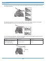
Hardtail bikes
• QUICK-LINK
Zero point
QUICK-LINK
1345
Zero point
2
4 3 12
4 links
QUICK-LINK
5 links

14
Adjustment
Checking the chain length
• Connecting pin
5 links
1345
Zero point
2
6 links
13456 2
Zero point
Full suspension bikes
* For full suspension bikes, check the length of the chain with the suspension in its fully
extended position.
• QUICK-LINK
QUICK-LINK
5 links
1345
Zero point
2
Zero point
13456
QUICK-LINK
6 links
2

15
Adjustment
Checking the chain length
• Connecting pin
6 links 7 links
13467 5
Zero point
2
Zero point
13456 2
Bike type Number of links added
Hardtail bikes
4 to 5 links + a QUICK-LINK
5 to 6 links + a connecting pin
Full suspension bikes
5 to 6 links + a QUICK-LINK
6 to 7 links + a connecting pin

16
Adjustment
Checking the chain length
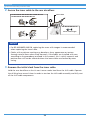
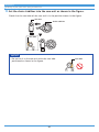
NOTICE
• The rear derailleur plate assembly is equipped with a pin or plate that prevents
chain derailment. When passing the chain through the rear derailleur, pass it
through the main body of the rear derailleur from the side of the chain
derailment prevention plate as shown in the figure.
• If the chain is not passed through the correct position, damage may be caused to
the chain or the rear derailleur.
Chain
derailment
prevention
plate
Chain
derailment
prevention
plate
• For full suspension bikes, length [a] will vary according to the movement of the
rear suspension.
After shifting to the largest chainring and the largest sprocket, make sure that the
chain length is not too short when dimension [a] is at its maximum extension.
If the chain length is too short, drivetrain components may be damaged due to
excessive load on the drivetrain.
[a']
[a]

17
Adjustment
Connection and securing of the inner cable
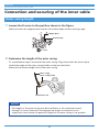
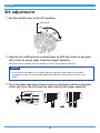
Connection and securing of the inner cable
Outer casing length
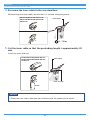
1. Loosen the B-screw to the position shown in the figure.
Make sure that the stopper plate touches the bracket body without leaving a gap.
B-screw
Stopper plate
Bracket body
2. Determine the length of the outer casing.
Fit a sealed outer cap to the end of the outer casing. Align the end of the outer cap to
the bottom edge of the outer casing holder on the rear derailleur.
Make sure to leave enough slack in the outer casing.
Outer casing
Outer casing holder
Sealed outer cap
NOTICE
• The length of the outer casing may be insufficient as the suspension moves
through its travel. Determine the appropriate length at the point in the
suspension travel where the potential length of the outer casing is the greatest.

18
Adjustment
Connection and securing of the inner cable
TECH TIPS
• If the motion of the rear derailleur is extreme, such as in bicycles with a rear
suspension, replacing the sealed outer cap with the supplied aluminum type
sealed outer cap is recommended.
Sealed outer cap Sealed outer cap
(aluminum type)
3. Cut off any excess outer casing with the cable cutter.
After cutting, return the outside of the outer casing to a perfect circle so that the inside
of the hole has a uniform shape.
4. Install the sealed outer cap to the end of the outer casing.
Route the inner cable through the outer casing.
Sealed outer cap

19
Adjustment
Connection and securing of the inner cable
5. Install the sealed outer cap with tongue and rubber shield onto the
outer casing stopper of the frame.
For bikes with full length outer casing, this step is not necessary.
Be careful not to bend the tongue.
Sealed outer cap
with tongue
Rubber shield
Connection and securing of the inner cable
CAUTION
• Do not allow the wheel to turn while securing the inner cable and installing the inner
end cap. Otherwise, you may touch the wheel and be injured.
1. Set the shifting lever in its initial position.
Operate the release lever 11 or more times for a 12-speed, 10 or more times for an
11-speed, and 9 or more times for a 10-speed.

20
Adjustment
Connection and securing of the inner cable
2. Secure the inner cable to the rear derailleur.
Inner cable
Cover with tongue
RD-M9100/RD-M9120
RD-M9120/RD-M8120/RD-M7120
RD-M9100/RD-M8100/RD-M8130/RD-M7100/
RD-M6100/RD-M5100/RD-M5130
NOTICE
• For RD-M9100/RD-M9120, replacing the cover with tongue is recommended
when replacing the inner cable.
• Cables with a polymer coating may develop a fuzzy appearance or texture
through natural wear when used. However, if the cables are installed with care
according to the procedures outlined in this manual, this is strictly cosmetic and
performance will not be affected where the inner cables are housed by outer
casing.
3. Remove the initial slack from the inner cable.
Hold the rear derailleur so that it won't move under load from the shift cable. Operate
the shifting lever several times in order to tension the shift cable assembly and fully seat
all the shift cable components.
Page is loading ...
Page is loading ...
Page is loading ...
Page is loading ...
Page is loading ...
Page is loading ...
Page is loading ...
Page is loading ...
Page is loading ...
Page is loading ...
Page is loading ...
Page is loading ...
Page is loading ...
Page is loading ...
Page is loading ...
Page is loading ...
Page is loading ...
Page is loading ...
Page is loading ...
Page is loading ...
Page is loading ...
Page is loading ...
Page is loading ...
Page is loading ...
Page is loading ...
-
 1
1
-
 2
2
-
 3
3
-
 4
4
-
 5
5
-
 6
6
-
 7
7
-
 8
8
-
 9
9
-
 10
10
-
 11
11
-
 12
12
-
 13
13
-
 14
14
-
 15
15
-
 16
16
-
 17
17
-
 18
18
-
 19
19
-
 20
20
-
 21
21
-
 22
22
-
 23
23
-
 24
24
-
 25
25
-
 26
26
-
 27
27
-
 28
28
-
 29
29
-
 30
30
-
 31
31
-
 32
32
-
 33
33
-
 34
34
-
 35
35
-
 36
36
-
 37
37
-
 38
38
-
 39
39
-
 40
40
-
 41
41
-
 42
42
-
 43
43
-
 44
44
-
 45
45


Ask a question and I''ll find the answer in the document
Finding information in a document is now easier with AI
Related papers
-
Shimano FD-AX60 Exploded View
-
Shimano RD-R2000 Dealer's Manual
-
Shimano SL-M3100 Dealer's Manual
-
-
Shimano RD-U5000 Dealer's Manual
-
Shimano FD-M4100 Dealer's Manual
-
Shimano RD-M8100 User manual
-
Shimano FD-RX400 Dealer's Manual
-
Shimano SW-R671 User manual
-
Shimano SL-TZ20 Dealer's Manual

