
Rev.B
INST-666
required. Gamber-Johnson specifically disclaims any responsibility for the improper use or installation of its products not consistent with the original vehicle manufactures specifications
Product Mounting Disclaimer
Gamber-Johnson is not liable under any theory of contract or tort law for any loss, damage, personal injury, special, incidental or consequential damages for personal injury or other damage
of any nature arising directly or indirectly as a result of the improper installation or use of its products in vehicle or any other application. In order to safely install and use Gamber-Johnson
products full consideration of vehicle occupants, vehicle systems (i.e., the location of fuel lines, brakes lines, electrical, drive train or other systems), air-bags and other safety equipment is
and recommendations, Gamber-Johnson product instruction sheets, or workmanship standards as endorsed through the Gamber-Johnson Certified Installer Program.
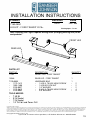
PARTS LIST
INSTALLATION INSTRUCTIONS
FormProduct Revision
If you need assistance or have questions, call Gamber-Johnson at 1-800-456-6868
Printing Spec:
PS-001
LEG KIT - FORD TRANSIT 2015+
7160-0552
TOOLS NEEDED
17201
•
1503-1400•
3130-0027•
1173-3812•
• 1/4" Drill bit and Power Drill
PART NO.
• 7/16 Socket
• 9/16 Socket
• T-40 Bit
DESCRIPTION
15346
7120-0659
1173-1412
QUANTITY
3130-0052• 4••
REAR LEG - FORD TRANSIT
HARDWARE BAG
FRONT LEG - FORD TRANSIT
•
1/4-20 NYLOCK NUT•
1/4" WASHER•
1/4-20 X .75 HEX HEAD SCREW
3/8" WASHER
• 3/8-16 X .75 HEX HEAD SCREW
1
1
1
2•
2•
2•
4•
Note: Installing this Leg Kit requires drilling holes (enlarging existing hole) to the
seat pedestal.
1/3
© Copyright 2014 Gamber-Johnson, LLC
REAR LEG
FRONT LEG

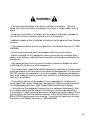
· You must read and follow all of these installation instructions. Failure to
follow all of these installation instructions may result in serious bodily injury or
death.
· Keep these installation instructions with the product and readily available in
the vehicle for future reference of other users of the product.
· Additional copies of the installation instructions can be obtained from Gamber
Johnson.
· If you need assistance or have any questions, call Gamber-Johnson at 1-800-
456-6868.
· Do not remove warning label from product under any circumstances.
· Before installation of any equipment always check area for routing of wires /
cables and if drilling is required check area where drilling above and below the
drilling area.
· High speed vehicle turns may cause a motion attachment product to swivel,
interfering with the driver or other equipment.
· The Vehicle Base, Upper Pole, Motion Attachment and Dock or Cradle should
not be positioned in the area where the airbag will be deployed if it is activated.
DO NOT position the equipment in front of an airbag. Equipment positioned in
front of an airbag can cause serious injury or death if and airbag was activated,
such as in an accident.
· The installer and user of this product(s) are responsible for installing and
using Upper Pole, Motion Attachment and Dock or Cradle assemblies outside
the airbag deployment zone. (See Product Mounting Disclaimer Below)
· If installation of the equipment requires that the equipment be placed in front
of an airbag, deactivate the airbag in the vehicle so it cannot be activated in
and accident. In order to secure permission for deactivating the airbag in these
circumstances, contact the National Highway Traffic Safety Administration at 1-
800-424-9393 to gain permission to do so. If you have any questions or need
assistance, call Gamber Johnson at 1-800-456-6868.
WARNING
2/3

FRONT LEG
REAR LEG
align slots with seat
mounting holes
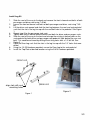
Install Leg-Kit
Slide the seat all the way to the back and remove the front in-bound seat bolts of both 1.
passenger and driver seat using T-40 bit.
Loosen the front out-bound seat bolts of both passenger and driver seat using T-40 2.
bit.
Lift the driver seat upward and slide the front leg between the seat and seat pedestal 3.
such that the slot in the leg line-up with the seat bolt hole in the pedestal. See Figure
1.
Repeat step 3 for the passenger side seat.4.
Tighten both front in-bound and out-bound seat bolts for driver and passenger seats.5.
Slide the seat all the way to the front and enlarge the existing in-bound holes on the 6.
seat pedestal for both driver and passenger seat pedestal (hole behind the rear seat
bolt). This could be achieved by drilling the existing holes with a 1/4" drill bit. See
Figure 2.
Place the Rear Leg such that the slots in the leg line-up with the 1/4" holes that were 7.
drilled.
Using the 1/4-20 Hardware provided, secure the Rear Leg to the seat pedestal.8.
Install the Top Plate at desired location using the 3/8-16 hardware provided. 9.
Figure 2
Figure 1
3/3
-
 1
1
-
 2
2
-
 3
3


Gamber-Johnson 2015+ Ford Transit Console Leg Kit Installation guide
- Type
- Installation guide
- This manual is also suitable for
Ask a question and I''ll find the answer in the document
Finding information in a document is now easier with AI
Related papers
-
Gamber-Johnson 2020+ Ford Police Interceptor Utility Trunk Box Leg Kit Installation guide
-
-
-
-
-
-
-
-
-