TITAN
™
INSTALLATION INSTRUCTIONS
INCANDESCENT DIMMERS, MAGNETIC LOW VOLTAGE DIMMERS,
FAN SPEED CONTROLS, DEHUMMER FAN SPEED CONTROLS,
FLUORESCENT DIMMERS P/N 340872
INCANDESCENT DIMMERS “CD” SERIES: These dimmers are for use with
Incandescent and Halogen lamps.
CAUTION: To reduce the risk of overheating and possible damage to other
equipment, do not install to control a receptacle, a fluorescent light, a motor-
operated appliance, or a transformer supplied appliance.
• Do not use this dimmer with incandescent lamps whose power require-
ments exceed maximum power (stated in Watts) of this control.
• Do not connect this dimmer to power source other than 120VAC, 60 Hz only.
• Use copper wire only.
MAGNETIC LOW VOLTAGE DIMMERS “CDLV” SERIES: These dimmers are for
use with Magnetic Low Voltage Incandescent and Halogen lamps.
CAUTION: To reduce the risk of overheating and possible damage to other
equipment, do not install to control a receptacle, a fluorescent light, or a
motor-operated appliance. Connect only in a 120VAC, 60 Hz circuit to control
the primary winding of a transformer supplied incandescent and halogen
lamp. The maximum VA rating of this dimmer applies to the transformer
input, not the load on the transformer secondary.
• Do not use to control a solid state electronic low voltage transformer.
• Do not use with inoperative or missing lamps. Use of this dimmer with
inoperative or missing lamps can create an over current condition which
may damage the transformer. Use transformers that incorporate thermal
protection or a fuse at the primary windings.
• Use copper wire only.
FAN SPEED CONTROLS “CDSC” SERIES: These controls are for use with
ceiling paddle fans with split-capacitor or shaded pole motors only. Use only
with ceiling paddle fans that are marked “Suitable for Use with Solid State
Fan Speed Controls.” Set multi-speed fans to their highest setting before
installing this control.
• Multiple ceiling paddle fans of the same type may be used if the maximum
power (stated in Amps) of this control is not exceeded.
• Do not connect this control to power source other than 120VAC, 60 Hz only.
• Use copper wire only.
• This control is intended for installation in either a metal outlet box or a
polymeric (plastic) outlet box.
DEHUMMER FAN SPEED CONTROLS “CDDH” SERIES: These controls are for
use with a single ceiling paddle fan only.
• Do not use this control with a ceiling paddle fan that exceeds the maximum
power (stated in Amps) of this control.
• Do not connect this control to power source other than 120VAC, 60 Hz only.
• Use copper wire only.
FLUORESCENT DIMMERS “CDFB” SERIES: These dimmers are for use with
electronic dimming ballasts that utilize 2-wire control (see TABLE 1 below):
• Use copper wire only.
FLUORESCENT DIMMERS “CD3FB” SERIES: These dimmers are for use with
electronic dimming ballasts that utilize 3-wire control (see TABLE 2 below):
• Use with Lutron FDB or ECO series Electronic Fluorescent Dimming
Ballasts only. Do not use with any other ballasts.
• Use copper wire only.
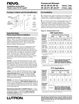
P
ACKAGE CONTENTS
One of the following Dimmers:
Narrow Dimmers Wide Dimmers
Cat no.: Cat no.: Cat no.: Cat no.:
CD700 CD703P CD1600 CD1603P
CD1100 CD1103P CD2000 CD2003P
CDLV700 CDLV703P CDLV1600 CDLV1603P
CDLV1100 CDLV1103P CDFB10 CDFB103P
CDFB5 CDFB53P CDFB16 CDFB163P
CDFB8 CDFB83P CDFB7-277 CDFB73P-277
CDSC6 CD3FB163P CDFB10-277 CDFB103P-277
CDDH16 CD3FB103P-277 CDSC12
CD3FB16
CD3FB10-277
Wire Nuts Coupler Small Coupler Wall Plate
WALL PLATE LABELING SYSTEM
(for use with wall plate that contains label holding slot)
These dimmer wall plates contain a label holding slot. A
0.33" x 1.5" label can be placed in this label holding slot.
These labels can be printed from an Avery
®
standard
template: Divider tab inserts 8-Tabs or equivalent.
Install the label with the following procedure:
1. Disconnect power to the circuit by removing fuse or
turning circuit breakers OFF.
2. Remove the wall plate by
placing a small flat head
screwdriver into one of
the four slots located at
the top and bottom of the
wall plate. Gently twist a
half turn until the plate
pops off.
3. Slide the label in from the
back side of the wall plate
(as shown at right).
C
ompatible
P&S Cat #
C
DFB5
CDFB8
CDFB53P
C
DFB83P
CDFB10
CDFB16
C
DFB103P
CDFB163P
CDFB7-277
CDFB10-277
CDFB73P-277
CDFB103P-277
Model
REZ-132-SC, REZ-2S32-SC, REZ-3S32-SC, REZ-154, REZ-2S54,
REZ-1Q18-M2, REZ-2Q18-M2, REZ-1T42-M2, REZ-2T42-M3,
R
EZ-1TTS40/REZ-1TTS40-SC, REZ-2TTS40/REZ-2TTS40-SC,
IEZ-2S24-D, REB-2S26-M1-LS-DIM/REB-2S26-M1-BS-DIM
2W-T426-120-1-S, 2W-T426-120-2-S, 2W-T432-120-1-S,
2W-T432-120-2-S, 2W-T832-120-1-S, 2W-T832-120-2-S
QTP1x32T8/UNV DIM, QTP2x32T8/UNV DIM, QTP3x32T8/UNV
D
IM, QTP4x32T8/UNV DIM
VEZ-132-SC, VEZ-2S32-SC, VEZ-3S32-SC, VEZ-154, VEZ-2S54,
VEZ-1Q18-M2, VEZ-2Q18-M2, VEZ-1T42-M2, VEZ-2T42-M3,
VEZ-1TTS40/VEZ-1TTS40-SC, VEZ-2TTS40/VEZ-2TTS40-SC,
IEZ-2S24-D
QTP1x32T8/UNV DIM, QTP2x32T8/UNV DIM, QTP3x32T8/UNV
DIM, QTP4x32T8/UNV DIM
Voltage
1
20VAC
60 HZ
277VAC
60 HZ
B
allast
Manufacturer
Advance
L
utron
Sylvania/
O
sram
Advance
Sylvania/
Osram
CD3FB16
CD3FB163P
CD3FB10-277
CD3FB103P-277
120VAC
60 HZ
277VAC
60 HZ
Lutron
Lutron
FDB-T418-120-1-S, FDB-T418-120-2-S,
FDB-T426-120-1-S, FDB-T426-120-2-S,
FDB-T418-120-1-S, FDB-T418-120-2-S,
FDB-T426-120-1-S, FDB-T426-120-2-S,
FDB-T432-120-1-S, FDB-T432-120-2-S,
FDB-T442-120-1-S, FDB-T442-120-2-S,
FDB-1643-120-1, FDB-1643-120-2,
FDB-1643-120-3, FDB-2227-120-1,
FDB-2227-120-2, FDB-2227-120-3,
FDB-2243-120-1, FDB-2243-120-2
FDB-T418-277-1-S, FDB-T418-277-2-S,
FDB-T426-277-1-S, FDB-T426-277-2-S,
FDB-T418-277-1-S, FDB-T418-277-2-S,
FDB-T426-277-1-S, FDB-T426-277-2-S,
FDB-T432-277-1-S, FDB-T432-277-2-S,
FDB-T442-277-1-S, FDB-T442-277-2-S,
FDB-1643-277-1, FDB-1643-277-2,
FDB-1643-277-3, FDB-2227-277-1,
FDB-2227-277-2, FDB-2227-277-3,
FDB-2243-277-1, FDB-2243-277-2
HL3-T426-120-1-S, HL3-T432-120-1-S,
FDB-T524-120-1, FDB-T524-120-2,
FDB-T539-120-1, FDB-T539-120-2,
FDB-T554-120-1, FDB-T554-120-2,
FDB-2427-120-1, FDB-2427-120-2,
FDB-2427-120-3, FDB-3627-120-1,
FDB-3627-120-2, FDB-3627-120-3,
FDB-4827-120-1, FDB-4827-120-2,
FDB-4827-120-3, FDB-6027-120-1,
FDB-6027-120-2, FDB-7280-120-1,
FDB-8480-120-1, FDB-9680-120-1,
H3DT832CUNV110, H3DT832CUNV117,
H3DT832CUNV210, H3DT832CUNV217
HL3-T426-277-1-S, HL3-T432-277-1-S,
FDB-T524-277-1, FDB-T524-277-2,
FDB-T539-277-1, FDB-T539-277-2,
FDB-T554-277-1, FDB-T554-277-2,
FDB-2427-277-1, FDB-2427-277-2,
FDB-2427-277-3, FDB-3627-277-1,
FDB-3627-277-2, FDB-3627-277-3,
FDB-4827-277-1, FDB-4827-277-2,
FDB-4827-277-3, FDB-6027-277-1,
FDB-6027-277-2, H3DT832CUNV110,
H3DT832CUNV117, H3DT832CUNV210,
H3DT832CUNV217
P&S
Cat. #
Voltage
Ballast
Manufacturer
1% – Hi-lume, Hi-lume 3D
Model
5% – Compact SE 10% – Eco-10
Table 1
Table 2
E3-T514C-120-1, E3-T514C-120-2,
E3-T521C-120-1, E3-T521C-120-2,
ECO-T528-120-1, ECO-T528-120-2,
ECO-T524-120-1, ECO-T524-120-2,
ECO-T5H39-120-1, ECO-T5H39-120-2,
ECO-T554-120-1, ECO-T554-120-2,
ECO-T539-120-1, ECO-T539-120-2,
ECO-T539-120-3, ECO-T540-120-1,
ECO-T540-120-2, ECO-T540-120-3,
ECO-T550-120-1, ECO-T550-120-2,
ECO-T817-120-1, ECO-T817-120-2,
ECO-T817-120-3, ECO-T825-120-1,
ECO-T825-120-2, ECO-T832-120-1-L,
ECO-T832-120-1-T, ECO-T832-120-2-L,
ECO-T832-120-2-T, ECO-T832-120-3
E3-T514C-277-1, E3-T514C-277-2,
E3-T521C-277-1, E3-T521C-277-2,
ECO-T528-277-1, ECO-T528-277-2,
ECO-T524-277-1, ECO-T524-277-2,
ECO-T5H39-277-1, ECO-T5H39-277-2,
ECO-T554-277-1, ECO-T554-277-2,
ECO-T539-277-1, ECO-T539-277-2,
ECO-T539-277-3, ECO-T540-277-1,
ECO-T540-277-2, ECO-T540-277-3,
ECO-T550-277-1, ECO-T550-277-2,
ECO-T817-277-1, ECO-T817-277-2,
ECO-T817-277-3, ECO-T825-277-1,
ECO-T825-277-2, E3-T832C-277-1,
ECO-T832-277-1-L, ECO-T832-277-1-T,
ECO-T832-277-1, E3-T832C-277-2,
ECO-T832-277-2-L, ECO-T832-277-2-T,
ECO-T832-277-2, ECO-T832-277-3