Page is loading ...

OPERATION MANUAL
CLASSIC 40 and CLASSIC 60
Unit Serial Number Range: 0711XXXX### to Present
(From July 2011 to Present)
READ THIS MANUAL CAREFULLY FOR INSTRUCTIONS ON CORRECT
INSTALLATION AND USAGE, AND READ ALL SAFEGUARDS
SECCIÓN EN ESPAÑOL
SECTION EN FRANÇAIS
AVAILABLE AT WWW.MOVINCOOL.COM

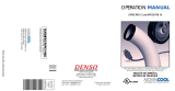
SERIAL NUMBER LOCATION AND IDENTIFICATION
Nameplate Label Position
Nameplate Label
COOLING AMPS. WITH PUMP
COMPR. OUTPUT
REFRIGERANT/TOTAL CHARGE
DESIGN PRESSURE LO/HI
PART NO./WEIGHT
SERIAL NO.
Month
Model
Sequential
Number
Year
© 2013 DENSO PRODUCTS AND SERVICES AMERICAS, INC.
All rights reserved. This book may not be reproduced or copied, in
whole or in part, without the written permission of the publisher.
DENSO PRODUCTS AND SERVICES AMERICAS, INC. reserves the
right to make changes without prior notice. MovinCool®, Office Pro®,
and SpotCool® are registered trademarks of DENSO Corporation.

OPERATION MANUAL
CLASSIC 40 and CLASSIC 60

Table of Contents
SERIAL NUMBER LOCATION AND IDENTIFICATION ................................... 2
FOREWORD ...................................................................................................... 5
Definition of Terms......................................................................................... 5
GENERAL WARNINGS & CAUTIONS.............................................................. 5
INVENTORY & ASSEMBLY .............................................................................. 6
Inventory ......................................................................................................... 6
Assembly of Exhaust Duct (For Classic 60 ONLY) ..................................... 8
INSTALLATION ................................................................................................. 9
Unit Overview.................................................................................................. 9
Exterior Dimensions..................................................................................... 10
Choosing an Installation Site ...................................................................... 12
Plugging in the Unit (For Classic 40 ONLY)............................................... 13
Power Supply and Field Wiring Connection (For Classic 60 ONLY) ....... 14
Optional Accessories and Set Up Configuration ...................................... 16
Wall Thermostat Connection (Millivolt System ONLY: Option) ............... 24
Warning Signal Connection (Output Signal Terminal L+ and L-)............. 27
Fire Alarm Control Panel Connection (Input Signal Terminal E+
and E-) .................................................................................................. 29
OPERATION .................................................................................................... 31
Features......................................................................................................... 31
Control Panel ................................................................................................ 32
Operating Modes .......................................................................................... 34
Operating in COOL Mode............................................................................. 35
Operating in FAN ONLY Mode..................................................................... 35
Changing from FAN ONLY Mode to COOL Mode ...................................... 35
Self-Diagnostic Codes ................................................................................. 36
DAILY INSPECTION & MAINTENANCE......................................................... 37
Clean the Air Filters...................................................................................... 37
Filter Removal Method ................................................................................. 37
Filter Element Cleaning Method.................................................................. 37
In-Season/Off-Season Inspection & Maintenance..................................... 38
TROUBLESHOOTING ..................................................................................... 40
Installation Check Sheet .............................................................................. 42
TECHNICAL SPECIFICATIONS...................................................................... 43

5
FOREWORD
Congratulations on purchasing the MovinCool spot cooling system. This manual
explains how to assemble, install and operate the MovinCool Classic 40, and
Classic 60 spot cooling system. Please read this operation manual thoroughly to
familiarize yourself with the features of the unit and to ensure years of reliable
operation.
You may also find it useful to keep this operation manual on hand for reference.
Components and/or procedures are subject to change without prior notice.
Definition of Terms
WARNING: Describes precautions that should be observed in order to
prevent injury to the user during installation or unit operation.
CAUTION: Describes precautions that should be observed in order to
prevent damage to the unit or its components, which may occur during
installation or unit operation if sufficient care is not taken.
Note: Provides additional information that facilitates installation or unit operation.
GENERAL WARNINGS & CAUTIONS
1. All electrical work, if necessary, should only be performed by qualified
electrical personnel. Repair to electrical components by non-certified
technicians may result in personal injury and/or damage to the unit. All
electrical components replaced must be genuine MovinCool parts, purchased
from an authorized reseller.
2. Installation should be conducted by a qualified technician only. DENSO and
DENSO affiliates are not responsible for injuries and/or damages caused by
improper installation.
3. Never fold or place heavy objects on the power cord.
This could result in damage to the power cord causing electrical shock or fire.
4. Do not place water or any other liquid on the unit. This can cause damage to
the unit and increase the risk of electrical shock.
5. Do not sit or stand on the unit.
6. Do not place hands or any object in the cool air outlet or exhaust duct.
Touching the fan, which is rotating at a high speed, is very hazardous.

6
INVENTORY & ASSEMBLY
Inventory
Classic 40
After unpacking your MovinCool unit, please check to make sure you have the
following items:
1. Classic 40 MovinCool Unit (1)
2. Clip (2)
3. Grommet (2)
4. Operation Manual/Product Registration (1)
Note: If any of these items were not included in the box or appear damaged,
please contact your MovinCool reseller for replacement.
CLASSIC 40 UNIT
CLIP GROMMET
OPERATION MANUAL /
PRODUCT REGISTRATION

7
INVENTORY & ASSEMBLY (cont.)
Inventory (cont.)
Classic 60
After unpacking your MovinCool unit, please check to make sure you have the
following items:
1. Classic 60 MovinCool Unit (1)
2. Exhaust Duct for Condenser (1)
3. Clip (2)
4. Grommet (2)
5. Operation Manual/Product Registration (1)
Note: Power cord is not supplied with Classic 60.
If any of these items were not included in the box or appear damaged, please
contact your MovinCool reseller for replacement.
CLASSIC 60 UNIT
CLIP GROMMET
OPERATION MANUAL /
PRODUCT REGISTRATION
EXHAUST DUCT FOR CONDENSER

8
INVENTORY & ASSEMBLY (cont.)
Assembly of Exhaust Duct (For Classic 60 ONLY)
1. Remove the exhaust duct from the package.
2. Install the exhaust duct to the unit, using eight (8) bolts provided in the
exhaust duct package.
EXHAUST DUCT
PACKAGE
M6 BOLTS (8)
EXHAUST DUCT

9
INSTALLATION
Unit Overview
Classic 40
Classic 60
EXHAUST DUCT
COOL AIR OUTLET
AIR FILTERS
CONTROL PANEL
POWER CORD
EXHAUST DUCT
COOL AIR OUTLET
CONTROL PANEL
AIR FILTERS

10
INSTALLATION (cont.)
Exterior Dimensions
Classic 40
2.8
37.8
4xM20
2.8
30.1
41.3
4.8
6.9
5.1
10.0
5.1
25.8
DIA. 13.8
DIA. 22.0
10.0
20.7
12.9
43.5
5.1
10.2
4.3
6XM6
2X6XM6
22.4
1.9 2.3
8.9 8.9
3.9
DIA. 20.7
11.811.8
23.6
1.6
1.6
1.2
25.6
DIA. 0.6
Unit: inch

11
INSTALLATION (cont.)
Exterior Dimensions (cont.)
Classic 60
8.729.9
4xDIA. 0.5
3.5
33.8
5.1
7.1
31.5
3.1 25.2 3.1
DIA. 25.1
DIA. 13.8
11.522.015.8
49.4
31.7
9.3
8.5
8XM6
6xM6
DIA. 26.2
4.3
1.3
DIA. 1.0
6.5 6.5
6.5
2.4
7.9 7.9
10.2
Unit: inch

12
INSTALLATION (cont.)
Choosing an Installation Site
CAUTION: Following are some precautions to consider before
choosing your installation site. Please review carefully as improper
installation may result in personal injury or damage to the unit.
1. Do not use the unit in areas where leakage of flammable gas may occur.
2. Do not use the unit in an environment which contains excessive amounts of
corrosive gas or vapor.
3. Do not place obstacles near the air inlet and outlet. Insufficient air flow may
activate the protection device or result in insufficient cooling.
4. Install the unit level with no more than 1.5 ° incline.
5. Install the unit in areas that can with-stand the weight of the unit. The Classic
40 unit weighs approximately 344 lb (156 kg), and the Classic 60 unit weighs
approximately 474 lb (215 kg).
6. Allow 18.0 in (457 mm) of unobstructed airflow for both the air inlets and
outlets.
7. Do not use the unit at condition below 75 °F (24 °C) or above 113 °F (45 °C)
50 %RH.
8. Provide proper ventilation if the unit is installed in an enclosed area.

13
INSTALLATION (cont.)
Plugging in the Unit (For Classic 40 ONLY)
1. Check the prongs and surface of the power cord plug for dust/dirt. If dust and/
or dirt are present, wipe off with a clean, dry cloth.
2. Check the power cord, plug and prongs for damage or excess play. If any
damage or excess play is found, contact your MovinCool reseller or a qualified
technician for repair.
WARNING:
1. If the power cord or plug is damaged, repair should only be
performed by qualified electrical personnel.
2. Do not connect/disconnect the power cord or attempt to operate
buttons with wet hands. This could result in electrical shock.
3. The power supply should be a dedicated single outlet circuit with a
UL approved short-circuit and ground fault protective breaker with
a recommended fuse size of 25 A (25 A maximum).
4. Because of potential safety hazards under a certain condition, we
strongly recommend against the use of an extension cord.
However, if you still elect to use an extension cord, it is absolutely
necessary that it is a UL listed, 4-wire grounding type appliance
extension cord, having a 4-blade grounding plug and a 4-slot
receptacle that plugs into the appliance. The marked rating of the
extension cord should be 220 V, 25 Aor equivalent.
CAUTION: The AC outlet should be rated minimum 25 A at 220 VAC, 3
phase, 60 Hz. Do not share the outlet with any other instrument or
equipment.
Note:
1. Make sure the AC outlet is free of dirt, dust, oil, water, or any other foreign
matter.
2. The Classic 40 is equipped with an approved NEMA plug configuration (L15-
30). The appropriate outlet must be used for this plug type.

14
INSTALLATION (cont.)
Power Supply and Field Wiring Connection (For Classic
60 ONLY)
Power Supply
• AC 460 V±10 %, 3 phase and 60 Hz. Do not connect the unit to any other power
supply.
• The power supply should be a dedicated single outlet circuit with a UL approved
short-circuit and ground fault protective breaker with a recommended fuse size
of 20 A (20 A maximum).
• Securely tighten each terminal.
CAUTION: Use a specified 20 A fuse. Do not use wiring, copper wire or
soldering instead of the fuse. The use of non-specified fuses can cause
machine failure or fire.
CIRCUIT BREAKER WITH
GROUND-FAULT PROTECTIVE
FUSE 20 A (20 A MAX.)
RS TG
RS TG
TERMINAL BLOCK OF Classic 60
GROUNDING
TERMINAL
GREEN
COLORED WIRE
POWER SOURCE
AC 460 V, 3 PHASE, 60 Hz

15
INSTALLATION (cont.)
Power Supply and Field Wiring Connection (For Classic
60 ONLY) (cont.)
Power Supply Wires
• Use at least 12 AWG for the power wires.
Cord type (4 wires): SO, SOT, SOOW or equivalent
Voltage rating: 600 V Minimum
Heat resistance: 140 °F (60 °C) or above
• Prepare three power wires for motive power and one wire (green) for grounding.
• Make sure to use conduit tubing when installing power wires.
Connection to Classic 60
1. Remove three (3) screws from the upper panel on the control panel side and
open the upper panel.
2. Pass the power wire through the
conduit hole in the left side
panel.
3. Attach the conduit tubing to the
conduit hole.
Trade size of conduit is 1/2 inch.
4. Connect the power wires to the
R, S, T and Grounding terminal.
Tightening torque: 0.96 ft•lbf (1.3
N•m)
Note: Classic 40 and Classic 60 are equipped with phase protectors.
1. The phase sequence is in order of R, S, and T. If the phase sequence is
reversed, the unit does not operate.
At this condition, exchange two of the power wires for R, S and T terminals.
2. Do not use an extension cord on a cord connected unit.
WARNING: All electrical work, should only be performed by qualified
electrical personnel. Repair to electrical components by non-certified
technicians may result in personal injury and/or damage to the unit.
SCREW (3)CONDUIT
HOLE

16
INSTALLATION (cont.)
Optional Accessories and Set Up Configuration
Using the optional accessories not only gives you the ability to customize the
cooling application, but also makes the unit work more efficiently.
Unit Installed on the Floor (For Classic 40 and Classic 60)
The unit can be used as a spot cooling system. More information is available at
WWW.MOVINCOOL.COM.
1. Standard Configuration
Without stand kit (For Classic 40 and Classic 60)
With stand kit (For Classic 40 ONLY)
Note: The maximum length of each duct is 6.6 ft. (2 m).
CHAMBER
TRIM RING
DUCT (6 in. DIA.)
CHAMBER
STAND KIT
DUCT (6 in. DIA.)
TRIM RING

17
INSTALLATION (cont.)
Optional Accessories and Set Up Configuration (cont.)
Unit Installed on the Floor (For Classic 40 and Classic 60)
2. Application Configuration
Note: The maximum length of duct “L” is 66 ft. (20 m).
Range of extension static pressure:
Number of blow off ports:
Classic 40 0.63 IWG (157 Pa) ~ 1.73 IWG (431 Pa)
Classic 60 0.57 IWG (142 Pa) ~ 1.35 IWG (336 Pa)
Classic 40 3 ~ 5
Classic 60 4 ~ 7
FLEXIBLE DUCT
(12 in. DIA.)
BLOWOFF DUCT
(6 in. DIA.)
“L”
TRIM RING
FLANGE
SUSPENSION
BAR OR WIRE
TEE

18
INSTALLATION (cont.)
Optional Accessories and Set Up Configuration (cont.)
Unit Suspended from the Ceiling (For Classic 40 ONLY)
When the unit is suspended from the ceiling, cooling air can be sent from the
bottom of the unit. More information is available at WWW.MOVINCOOL.COM.
WARNING: Make sure that the ceiling structure is capable of
supporting the weigh of the unit, suspension hardware, and the
accessories.
Note:
1. Use standard suspension metal fittings.
2. Do not suspend the unit from the ceiling of a lightweight steel-frame building or
wooden building.
3. Make sure to lock the shackle pin with copper wire.
4. Make sure to securely tighten the nut-tightening portion with double-nut locking.
5. If you are uncertain about the strength of ceiling structure, from which the unit
is suspended, consult the architect.
6. When working in high places during the installation of unit, provide positive
safeguards, such as using a lifeline.
7. After the unit is suspended from the ceiling, make sure that the unit is level. If
the unit is not level, adjust each suspension length of the unit with an eyebolt.
If the unit slans more than 1.5° horizontally, the drain water will overflow.
8. When the unit is configured as suspended from the ceiling, the signal output can
be used with alarm speaker or light indicator to monitor proper operation.
U-BOLT
EYE BOLT
EYE NUT
SECURELY TIGHTEN WITH
DOUBLE NUT LOCKING
LOCK BY BINDING WITH
1/16 in. DIA. COPPER WIRE
SHACKLE
BRACKET
SPAN OF BUILDING
DUCT
SHACKLE
SHACKLE
SHACKLE PIN
ROD
ROD

19
INSTALLATION (cont.)
Optional Accessories and Set Up Configuration (cont.)
Unit Suspended from the Ceiling (For Classic 40 ONLY)
1. Standard Configuration
Note:
1. The maximum length of one
duct is 6.6 ft. (2 m). Suspend
the duct as required with
wires or suspension bars.
2. When installing the drain
pipe, make sure it is angled
downward for proper
drainage.
3. Check following items:
• No kinks or bends on the
drain hose.
• No trap in the drain hose.
• The end of the drain hose
should be higher than the
water level at the drain.
• No dripping from the drain hose at the clamping area.
• When installing the unit, empty the drain pan by draining out the water
through the drain pan drain pipe.
CHAMBER
TRIM RING
DRAIN PIPE
DRAIN HOSE
(5/8 in. ID.)
DUCT
(6 in. DIA.)

20
INSTALLATION (cont.)
Optional Accessories and Set Up Configuration (cont.)
Unit Suspended from the Ceiling (For Classic 40 ONLY)
2. Application Configuration
Note: The maximum length of duct “L” is 66 ft. (20 m).
Range of extension static pressure: 0.63 IWG (157 Pa) ~ 1.73 IWG (431 Pa)
Number of blow off ports: 3
~ 5
DRAIN PIPE
TEE
“L”
FLANGE
DRAIN HOSE (5/8 in. ID.)
SUSPENSION
BAR OR WIRE
FLEXIBLE DUCT
(12 in. DIA.)
BLOWOFF DUCT
(6 in. DIA.)
TRIM RING
/