Page is loading ...

TAURUS DX 2 SERIES
Low Light Box Camera
User’s Manual
Ver. 2.0

1
Table of Contents
1. Overview .................................................................................................................................. 2
1.1 Features ........................................................................................................................ 2
1.2 Package Contents ......................................................................................................... 3
1.3 Dimensions .................................................................................................................... 4
1.4 Connectors .................................................................................................................... 5
1.4.1 Light Sensor (ABF Models Only) ................................................................... 6
2. Camera Cabling ....................................................................................................................... 6
2.1 Power Connection ......................................................................................................... 6
2.2 Ethernet Cable Connection ........................................................................................... 6
2.3 Lens Mounting ............................................................................................................... 7
2.4 Alarm I/O Connection .................................................................................................... 7
2.5 RS-485 Connection (DC12V/AC24V/PoE Models) ....................................................... 7
3. System Requirements ............................................................................................................ 8
4. Access Camera ....................................................................................................................... 9
4.1 Lock ABF Function (ABF Models Only) ....................................................................... 13
5. Setup Video Resolution ........................................................................................................ 14
6. Configuration File Export / Import ....................................................................................... 15
7. Tech Support Information .................................................................................................... 16
7.1 Delete the Existing DCViewer ..................................................................................... 16
7.2 Setup Internet Security ................................................................................................ 17
7.3 Back Focus Adjustment (Non-ABF Models Only) ....................................................... 18
Appendix: Technical Specifications

2
1. Overview
Full HD Multi-Streams Ultra-WDR Box IP Camera features multiple streams, and
supports up to 1080p @ 60 fps. Ultra Dynamic Range offers excellent images
from combined two/four shutter speeds exposed pictures under extreme high
contrast environments.
Besides excellent wide dynamic range performance, with latest CMOS sensor,
the camera is also capable of handling the surveillance in nearly total darkness
environments. Combining the advantages of shutter WDR and low light ability,
the camera is especially ideal for traffic application and entrance surveillance.
Moreover, Full HD Multi-Streams Ultra-WDR Box IP Camera is built-in with Auto
Back Focus (ABF) function. User can simply adjust focus by clicking control
buttons on webpage that makes focus adjustment easier and also makes remote
focus tuning available after installation.
1.1 Features
1.3 MP / 2MP Sony Progressive Scan CMOS Sensor
Quad Streams Compression- H.264 Baseline / Main / High Profile + MJPEG
Quad Streams Support
Dual Streams, Full HD 1080P @ 60fps + D1 @ 30fps
Smart Event Function-
Motion Detection / Network Failure Detection / Tampering Alarm / Periodical
Event / Manual Trigger / Face Detection / Audio Detection
Ultra Dynamic Range
Auto Back Focus (ABF)*
Text Overlay and Privacy Masks
microSD Card Support
BNC Analog Output
Triple Power Support- PoE / DC 12V / AC 24V*
RS-485 Support*
ONVIF Profile S Conformance
(*) Optional

3
1.2 Package Contents
Please check the package containing the following items listed below.
Full HD Multi-Streams
Ultra-WDR Box IP Camera
Back Focus Adjuster*
Quick Guide
*For Non-ABF models.
NOTE: To purchase power adaptor, please contact the camera
manufacturer for further information.

4
1.3 Dimensions
The IP camera’s dimensions are shown below.
Non-ABF Models
ABF Models

5
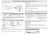
1.4 Connectors
The diagram below shows the various connectors of the camera. Definition for
each connector is given as follows.
DC 12V / PoE DC 12V / AC 24V / PoE
No.
Item
Pin
Definition
Remarks
1
Audio I/O
(Line In/Out)
- Two-way audio transmission
2
Power LED
-
For power connection indication (green light)
3
Default Button -
Press the button with a proper tool for at least 20
seconds to restore the system.
4
Auto Iris
-
For auto iris lens connection
5
RJ-45
-
For network and PoE connections
6
Network LEDs
-
For network connection and activity indication
7
Alarm I/O *
1
Alarm Out +
Alarm connection
2
Alarm Out –
3
Alarm In +
4
Alarm In –
5
GND
Ground connection
6
D –
RS-485 connection
7
D +
8
BNC
-
For analogue video output
9
microSD Card Slot -
Insert the microSD card into the card slot to store
videos and snapshots. Do not remove the microSD
card when the camera is powered on.
10
Power
(DC12V / AC 24V)
(AC 24V Model)
+
DC 12V AC 24V 1
Power connection
DC 12V
Reserved
AC 24V GND
-
DC 12V GND
AC 24V 2
*Do NOT connect external power supply to the alarm I/O connector of the camera.
NOTE: It is not recommended to record with the microSD card for 24/7
continuously, as it may not be able to support long term continuous data
read/write. Please contact the manufacturer of the microSD card for
information regarding the reliability and the life expectancy.

6
1.4.1 Light Sensor (ABF Models Only)
For ABF models, a light sensor is located at the front of the cameras. The location
and definition of the light sensor is as below.
No.
Item
Definition
1
Light Sensor
Ambient light detection for day/night switching function.
2. Camera Cabling
Please follow the instructions below to complete IP camera installation.
2.1 Power Connection
Please refer to section Connectors. Alternatively, users can power up the camera
by PoE if a Power Sourcing Equipment (PSE) switch is available. Refer to the
section below for Ethernet cable connection.
NOTE: If PoE is used, make sure PSE is in use in the network.
2.2 Ethernet Cable Connection
To have best transmission quality, cable length shall not exceed 100 meters.
Connect one end of the Ethernet cable to the RJ-45 connector of the camera,
and the other end of the cable to the network switch or PC. The RJ-45 port
networks without routing to the outside plant.
NOTE: In some cases Ethernet crossover cable might be needed when
connecting the camera directly to the PC.

7
Check the status of the link indicator and the activity indicator LEDs. If the LEDs
are unlit, please check the LAN connection.
Green Link Light indicates good network connection.
Orange Activity Light flashes for network activity indication.
2.3 Lens Mounting
Follow the steps below to mount the C/CS Mount Lens to the camera.
Step 1: Remove the plastic cover of the camera.
Step 2: Remove the dustproof protective film from the CMOS image sensor.
Step 3: For Non-ABF models, mount the C/CS Mount Adapter to the camera.
Step 4: Attach the C/CS Mount Lens to the adapter.
C/CS Mount Adapter Completion
2.4 Alarm I/O Connection
The camera supports one alarm input and one relay output for alarm application.
Refer to alarm pin definition below to connect alarm devices to the IP camera if
needed.
DC 12V / PoE
DC 12V / AC 24V / PoE
1. Alarm Out +
2. Alarm In −
3. Alarm Out +
4. Alarm In −
2.5 RS-485 Connection (DC12V/AC24V/PoE Models)
The RS-485 connector is the interface for connecting with the pan & tilt
positioning system.
6. D
−
7. D +

8
3. System Requirements
To perform the IP camera via web browser, please ensure the PC is in good
network connection, and meet system requirements as described below.
Items System Requirement
Personal Computer
Minimum :
1. Intel® CoreTM i5-2430M @ 2.4 GHz
2. 4 GB RAM
Recommended :
1. Intel® CoreTM i7-870 @ 2.93 GHz
2. 8 GB RAM
Operating System
Windows VISTA / Windows XP / Windows 7
Web Browser
Microsoft Internet Explorer 7.0 or later (recommended)
Firefox (32-bit)
Safari
Network Card
10Base-T (10 Mbps), 100Base-TX (100 Mbps) or
1000Base-T operation
Viewer
ActiveX control plug-in for Microsoft IE
Apple QuickTime 7.7.7 or before for Firefox
NOTE: The ITE is to be connected only to PoE networks without routing
to the outside plant or equivalent description.

9
4. Access Camera
For initial access to the IP camera, users can search the camera through the
installer program: DeviceSearch.exe.
Accessing the Camera by Device Search Software
Step 1: Double click on the program Device Search.exe.
Step 2: After its window appears, click on the <Device Search> button on the
top. All the finding IP devices will be listed in the page.
Step 3: Find the camera in the list by its IP address and click on it. The default
IP address of the camera is: 192.168.0.250.
Step 4: The default IP address of the camera may not be in the same LAN as
the IP address of the PC. If so, the IP address of the camera needs to
be changed. Right click on the camera and click <Network Setup>.
Meanwhile, record the MAC address of the camera, for future
identification.
Step 5: The <Network Setup> page will come out. Select <DHCP> and click
<Apply> down the page. The camera will be assigned with a new IP
address.
Step 6: Click <OK> on the Note of setting change. Wait for one minute to re-
search the camera.
Step 7: Click on the <Device Search> button to re-search all the devices. Find
the camera in the list by its MAC address. Then double click or right
click and select <Browse> to access the camera directly via a web
browser.

10
Step 8: A prompt window requesting for default username and password will
appear. Enter the default username and password shown below to
login to the camera.
Login ID
Password
Admin 1234
NOTE: ID and password are case sensitive.
NOTE: It is strongly advised that administrator’s password be
altered for the security concerns. Refer to the Full HD Multi-
Streams Ultra-WDR IP Camera Menu Tree for further details.
Installing DCViewer Software Online
For the initial access to the IP camera, a client program, DCViewer, will be
automatically installed to the PC when connecting to the camera.
If the web browser doesn’t allow DCViewer installation, please check the Internet
security settings or ActiveX controls and plug-ins settings (refer to section Setup
Internet Security) to continue the process.
The Information Bar (just below the URL bar) may come out and ask for
permission to install the ActiveX Control for displaying video in browser.
Right click on the Information Bar and select <Install ActiveX Control…> to allow
the installation.
The download procedure of DCViewer software is specified as follows.
Step 1: In the DCViewer installation window, click on <Next> to start
installation.
Step 2: The status bar will show the installation progress. After the installation
is completed, click on <Finish> to exit the installation process.
Step 3: Click on <Finish> to close the DCViewer installation page.

11
Once the Viewer is successfully installed, the Home page of the camera will be
displayed as the figure below.
Non-ABF Models

12
ABF Models
NOTE: For more details about the function buttons on the Home page,
please refer to the Full HD Multi-Streams Ultra-WDR IP Camera Menu
Tree.

13
4.1 Lock ABF Function (ABF Models Only)
Lock function is to lock the ABF function of the camera after focus is adjusted to
the best position. This function is to prevent the camera from being out of focus
when the camera is moved afterwards or is accidentally adjusted locally or
remotely via NVR/VMS.
Step 1:
Once the camera is powered on, click on < >.
Step 2:
Manually adjust the lens to the approximate zoom and focus position.
Step 3:
Check the <Precise AF> box and click < >.
Step 4:
Click on < > to lock the current focus position of the camera.
Note that all function items related to focus cannot be accessed. Click
< > to disable this function and adjust the focus of the camera.

14
5. Setup Video Resolution
Users can setup video resolution on Video Format page of the user-friendly
browser-based configuration interface.
Video Format can be found under this path: Streaming> Video Format.
The default values of video resolution are as below.
1.3M
H.264- 1280 x 720 (25/30 fps) + H.264- 1280 x 720 (25/30 fps)
2M
H.264- 1920 x 1080 (25/30 fps) +
H.264- 720 x 480 (25 fps) / 720 x 576 (30 fps)
H.264- 1920 x 1080 (25/30 fps) + H.264- 640 x 480 (25/30 fps)

15
6. Configuration File Export / Import
To export / import configuration files, users can access the Maintenance page on
the user-friendly browser-based configuration interface.
The Maintenance setting can be found under this path: System> Maintenance.
Users can export configuration files to a specified location and retrieve data by
uploading an existing configuration file to the camera. It is especially convenient
to make multiple cameras having the same configuration.
Export
Users can save the system settings by exporting the configuration file (.bin) to a
specified location for future use. Click on the <Export> button, and the popup
File Download window will come out Click on <Save> and specify a desired
location for saving the configuration file.
Upload
To copy a configuration file to the camera, click on <Browse> to select the
configuration file and then click on the <Upload> button for uploading.

16
7. Tech Support Information
This chapter will introduce how to delete previously-installed DCViewer in the PC
and how to setup the Internet security. In addition, how to adjust the back focus
of the cameras will also be described here.
NOTE: Adjusting the back focus of the camera is only available for Non-
ABF models.
7.1 Delete the Existing DCViewer
For users who have installed the DCViewer in the PC previously, please first
remove the existing DCViewer from the PC before accessing to the IP camera.
Deleting the DCViewer
In the Windows <Start Menu>, activate <Control Panel>, and then double click
on <Add or Remove Programs>. In the <Currently installed programs> list, select
<DCViewer> and click on the button <Remove> to uninstall the existing
DCViewer.
Deleting Temporary Internet Files
To improve browser performance, it is suggested to clean up the all the files in
the Temporary Internet Files. The procedure is as follows.
Step 1: Click on the <Tools> tab on the menu bar and select <Internet Options>.
Step 2: Click on the <Delete> button under <Browsing history> section.
Step 3: In the appeared window, tick the box beside the <Temporary Internet
files> and click on <Delete> to start deleting the files.

17
7.2 Setup Internet Security
If ActiveX control installation is blocked, please either set Internet security level
to default or change ActiveX controls and plug-ins settings.
Internet Security Level: Default
Step 1: Start the Internet Explorer (IE).
Step 2: Click on the <Tools> tab on the menu bar and select <Internet Options>.
Step 3: Click on the <Security> tab, and select <Internet> zone.
Step 4: Down the page, click on the <Default Level> button and click on <OK>
to confirm the setting. Close the browser window, and restart a new
one later to access the camera.
ActiveX Controls and Plug-ins Settings
Step 1: Repeat Step 1 to Step 3 of the previous section above.
Step 2: Down the page, click on the <Custom Level> button to change ActiveX
controls and plug-ins settings. The Security Settings window will pop up.
Step 3: Under <ActiveX controls and plug-ins>, set ALL items (as listed below)
to <Enable> or <Prompt>. Please note that the items vary by IE version.
ActiveX controls and plug-ins settings:
1. Binary and script behaviors.
2. Download signed ActiveX controls.
3. Download unsigned ActiveX controls.
4. Allow previously unused ActiveX controls to run without prompt.
5. Allow Scriptlets.
6. Automatic prompting for ActiveX controls.
7. Initialize and script ActiveX controls not marked as safe for scripting.
8. Run ActiveX controls and plug-ins.
9. Only allow approved domains to use ActiveX without prompt.
10. Script ActiveX controls marked safe for scripting*.
11. Display video and animation on a webpage that does not use external media player.
Step 4: Click on <OK> to accept the settings. A prompt window will appear for
confirming the setting changes, click <Yes(Y)> to close the Security
Setting window.
Step 5: Click on <OK> to close the Internet Options screen.
Step 6: Close the browser window, and restart a new one later to access the IP
camera.

18
7.3 Back Focus Adjustment (Non-ABF Models Only)
This section is for Non-ABF models only. Follow the instructions below to adjust
the back focus of the camera.
When to adjust back focus
Back Focus refers to the distance from the rear lens element to the camera focal
plane. In most cases, it is required to adjust back focus only when the camera’s
lens cannot hold focus throughout its zoom range.
Tools required
Tools required when carrying out back focus adjustment include:
1. Back focus adjuster (in the IP camera’s package)
2. Test chart / contrasting object
How to adjust back focus
Step 1: Set the camera on a stable mount, and place the test chart or the
contrasting object at a far location (at least 10 meters).
Step 2: Adjust the focus to infinite far (∞) position.
Step 3: Turn the zoom adjustment bar to the extreme telephoto position, and
then focus on the test chart or the contrasting object.
Step 4: Turn the zoom adjustment bar to wide-angle position, and then focus on
the test chart or the contrasting object.
Step 5: Loosen the back focus ring’s retaining screw with the supplied adjuster,
and adjust the back focus ring for sharp image.
Step 6: Repeat Step 3 to Step 5 and adjust the back focus ring until focus can
be held throughout the zoom range.
Step 7: Tighten the retaining screw to fasten the back focus ring.
/