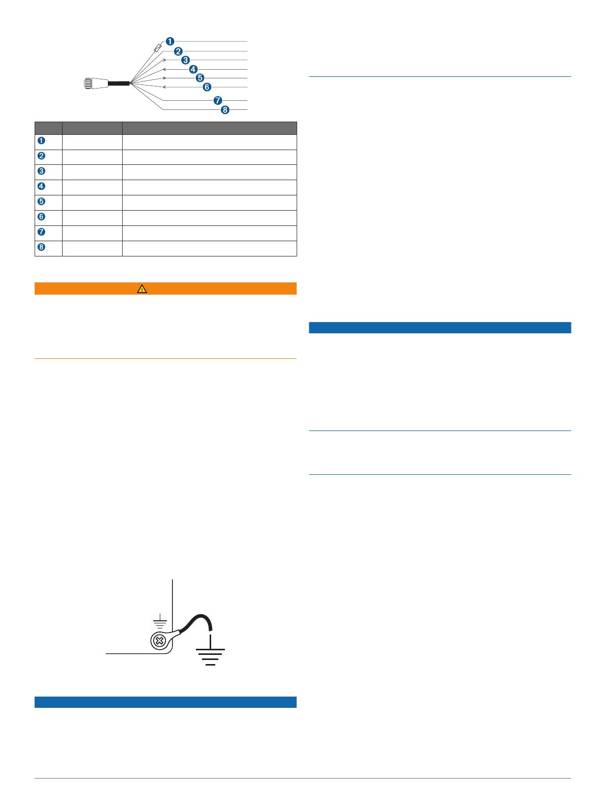
Item Wire Color Wire Function
Red Power
Black Ground (power and NMEA 0183)
Blue NMEA 0183 internal port 1 Tx (Out)
Brown NMEA 0183 internal port 1 Rx (In)
Gray NMEA 0183 internal port 2 Tx (Out)
Violet NMEA 0183 internal port 2 Rx (In)
Orange Accessory on
Yellow Alarm low
Connecting the Wiring Harness to Power
WARNING
When connecting the power cable, do not remove the in-line
fuse holder. To prevent the possibility of injury or product
damage caused by fire or overheating, the appropriate fuse
must be in place as indicated in the product specifications. In
addition, connecting the power cable without the appropriate
fuse in place voids the product warranty.
1
Route the wiring harness to the power source and to the
device.
2
Connect the red wire to the positive (+) battery terminal, and
connect the black wire to the negative (-) battery terminal.
3
If necessary, install the locking ring and O-ring on the end of
the wiring harness.
4
Insert the cable into the POWER connector on the back of
the device, pushing firmly.
5
Turn the locking ring clockwise to attach the cable to the
device.
Additional Grounding Consideration
This consideration is applicable only to devices that have a
grounding screw. Not all models have a grounding screw.
This device should not need additional chassis grounding in
most installation situations. If you experience interference, the
grounding screw on the housing can be used to connect the
device to the water ground of the boat to help avoid the
interference.
Garmin Marine Network Considerations
NOTICE
A Garmin Marine Network PoE Isolation Coupler
(010-10580-10) must be used when connecting any third-party
device, such as a FLIR
®
camera, to a Garmin Marine Network.
Connecting a Power over Ethernet (PoE) device directly to a
Garmin Marine Network chartplotter damages the Garmin
chartplotter and may damage the PoE device. Connecting any
third-party device directly to a Garmin Marine Network
chartplotter will cause abnormal behavior on the Garmin
devices, including the devices not properly turning off or the
software becoming inoperable.
This device can connect to additional Garmin Marine Network
devices to share data such as radar, sonar, and detailed
mapping. When connecting Garmin Marine Network devices to
this device, observe these considerations.
• All devices connected to the Garmin Marine Network must be
connected to the same ground. If multiple power sources are
used for Garmin Marine Network devices, you must tie all
ground connections from all power supplies together using a
low resistance connection or tie them to a common ground
bus bar, if available.
• A Garmin Marine Network cable must be used for all Garmin
Marine Network connections.
◦ Third-party CAT5 cable and RJ45 connectors must not be
used for Garmin Marine Network connections.
◦ Additional Garmin Marine Network cables and connectors
are available from your Garmin dealer.
• The NETWORK ports on the device each act as a network
switch. Any compatible device can be connected to any
NETWORK port to share data with all devices on the boat
connected by a Garmin Marine Network cable.
NMEA 2000
®
Considerations
NOTICE
If you are connecting this device to an existing NMEA 2000
network, the NMEA 2000 network should already be connected
to power. Do not connect the NMEA 2000 power cable to an
existing NMEA 2000 network, because only one power source
should be connected to a NMEA 2000 network.
If you are connecting this device to an existing NMEA 2000
network or engine network by another manufacturer, you should
install a NMEA 2000 Power Isolator (010-11580-00) between
the existing network and the Garmin devices.
If you are installing a NMEA 2000 power cable, you must
connect it to the boat ignition switch or through another in-line
switch. NMEA 2000 devices will drain your battery if the NMEA
2000 power cable is connected to the battery directly.
This device can connect to a NMEA 2000 network on your boat
to share data from NMEA 2000 compatible devices such as a
GPS antenna or a VHF radio. The included NMEA 2000 cables
and connectors allow you to connect the device to your existing
NMEA 2000 network. If you do not have an existing NMEA 2000
network you can create a basic one using cables from Garmin.
If you are unfamiliar with NMEA 2000, you should read the
“NMEA 2000 Network Fundamentals” chapter of the Technical
Reference for NMEA 2000 Products. You can find this document
using the “Manuals” link on the product page for your device at
www.garmin.com.
The port labeled NMEA 2000 is used to connect the device to a
standard NMEA 2000 network.
3