Page is loading ...

Relion
®
650 series
Transformer protection RET650
Product Guide

Contents
1. 650 series overview..............................................3
2. Application...........................................................3
3. Available functions...............................................7
4. Differential protection.........................................17
5. Current protection..............................................18
6. Voltage protection..............................................19
7. Frequency protection.........................................20
8. Secondary system supervision..........................21
9. Control................................................................21
10. Logic..................................................................22
11. Monitoring.........................................................23
12. Metering............................................................26
13. Human Machine interface.................................26
14. Basic IED functions...........................................27
15. Station communication.....................................28
16. Hardware description........................................29
17. Connection diagrams........................................30
18. Technical data...................................................37
19. Ordering............................................................73
Disclaimer
The information in this document is subject to change without notice and should not be construed as a commitment by ABB AB. ABB AB assumes
no responsibility for any errors that may appear in this document.
© Copyright 2011 ABB AB.
All rights reserved.
Trademarks
ABB and Relion are registered trademarks of ABB Group. All other brand or product names mentioned in this document may be trademarks or
registered trademarks of their respective holders.
Transformer protection RET650 1MRK 504 127-BEN -
Product version: 1.1 Issued: February 2011
2 ABB

1. 650 series overview
The 650 series IEDs provide optimum 'off-the-
shelf', ready-to-use solutions. It is configured
with complete protection functionality and
default parameters to meet the needs of a
wide range of applications for generation
transmission and sub-transmission grids.
The 650 series IEDs include:
• Complete ready-made solutions optimized
for a wide range of applications for
generation, transmission and sub-
transmission grids.
• Support for user-defined names in the local
language for signal and function
engineering.
• Minimized parameter setting based on
default values and ABB's new global base
value concept. You only need to set those
parameters specific to your own
application, such as the line data.
• GOOSE messaging for horizontal
communication.
• Extended HMI functionality with 15
dynamic three-color-indication LEDs per
page, on up to three pages, and
configurable push-button shortcuts for
different actions.
• Programmable LED text-based labels.
• Settable 1A/5A -rated current inputs.
2. Application
RET650 provides fast and selective
protection, monitoring and control for two-
and three-winding transformers,
autotransformers, generator-transformer units
and shunt reactors. The transformer IED is
designed to operate correctly over a wide
frequency range in order to accommodate
power system frequency variations during
disturbances and generator start-up and shut-
down.
A very fast differential protection function,
with automatic CT ratio matching and vector
group compensation, makes this IED the
ideal solution even for the most demanding
applications. Since RET650 has very low
requirements on the main CTs, no
interposing CTs are required. The differential
protection function is provided with 2nd
harmonic and wave-block restraint features to
avoid tripping for magnetizing inrush current,
and 5th harmonic restraint to avoid tripping
for overexcitation.
The differential function offers a high
sensitivity for low-level internal faults. The
unique and innovative sensitive differential
protection feature of the RET650 provides the
best possible coverage for winding internal
turn-to-turn faults, based on well-known
theory of symmetrical components .
Low impedance restricted earth-fault
protection function are available as
complimentary sensitive and fast main
protection against winding earth faults. This
function includes a directional zero-sequence
current criterion for additional security.
Tripping from Pressure relief/Buchholz and
temperature devices can be done through the
transformer IED where pulsing, lock-out
contact output and so on, is performed. The
binary inputs are heavily stabilized against
disturbance to prevent incorrect operations at
for example, dc system capacitive discharges
or DC earth faults.
Versatile phase, earth, negative and zero
sequence overcurrent functions, which can be
made directional, provide further alternative
backup protection. Thermal overload with
two time-constants, volts per hertz, over/
under voltage are also available.
A built-in disturbance and event recorders
provide valuable data to the user about status
and operation for post-fault disturbance
analysis.
Breaker failure protection allows high speed
back-up tripping of surrounding breakers.
Transformer protection RET650 1MRK 504 127-BEN -
Product version: 1.1 Issued: February 2011
Revision: -
ABB 3

Disturbance recording is available to allow
independent post-fault analysis after primary
disturbances.
Three packages have been defined for the
following applications:
• Two-winding transformer in single
breaker arrangements (A01)
• Three-winding transformer in single
breaker arrangements (A05)
• Tap changer control (A07)
The packages are configured and ready for
direct use. Analog and tripping IO has been
pre-defined for basic use. Other signals need
to be applied as required for each application.
The graphical configuration tool ensures
simple and fast testing and commissioning.
Transformer protection RET650 1MRK 504 127-BEN -
Product version: 1.1 Issued: February 2011
4 ABB

T2W PDIF
87T 3Id/I
CC RBRF
50BF 3I> BF
CC RBRF
50BF 3I> BF
OC4 PTOC
50/51 3I>
OC4 PTOC
51/67 3I>
CC RPLD
52PD PD
EF4 PTOC
51N
IN>
CC RPLD
52PD PD
TR PTTR
49 Ith
C MSQI
Meter.
V MMXU
Meter.
C MMXU
Meter.
CV MMXN
Meter.
TCS SCBR
Cond
TCS SCBR
Cond
SPVN ZBAT
Cond
TR8 ATCC
90
U
TCM YLTC
84
UV2 PTUV
27 U<
OV2 PTOV
59 U>
PH PIOC
50 3I>>
TR PTTR
49 Ith
REF PDIF
87N IdN/I
Other configured functions
REF PDIF
87N IdN/I
EF4 PTOC
51N/67N
IN>
DRP RDRE
Mont.
Y
Y
¨
ROV2 PTOV
59N 3U0>
RET650 A01 - 2 Winding Transformer protection 10AI (8I+2U)
20 MVA
110±11*1.5% / 21 kV
105 / 550 A
YNd5
20 kV Bus
110 kV Bus
200/1
600/1
20kV/100V
200/1
600/1
IEC61850
ANSI IEC
Function Enabled
in Settings
IEC61850
ANSI IEC
Function Disabled
in Settings
W1
W2
IEC09000645-2-en.vsd
IEC09000645 V2 EN
Figure 1. A typical protection application for a two-winding transformer in single breaker
arrangement
Transformer protection RET650 1MRK 504 127-BEN -
Product version: 1.1 Issued: February 2011
ABB 5

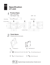
RET650 A05 - 3 Winding Transformer protection 20AI 2*(6I+4U)
W1
T3W PDIF
87T 3Id/I
CC RBRF
50BF 3I> BF
CC RBRF
50BF 3I> BF
OC4 PTOC
50/51 3I>
OC4 PTOC
51/67 3I>
CC RPLD
52PD PD
CC RBRF
50BF 3I> BF
CC RPLD
52PD PD
EF4 PTOC
51N
IN>
CC RPLD
52PD PD
TR PTTR
49 Ith
TR PTTR
49 Ith
V MSQI
Meter.
C MSQI
Meter.
V MMXU
Meter.
C MMXU
Meter.
CV MMXN
Meter.
V MSQI
Meter.
C MSQI
Meter.
V MMXU
Meter.
C MMXU
Meter.
CV MMXN
Meter.
TCS SCBR
Cond
TCS SCBR
Cond
TCS SCBR
Cond
SPVN ZBAT
Cond
TR8 ATCC
90
U
TCM YLTC
84
UV2 PTUV
27 U<
OV2 PTOV
59 U>
PH PIOC
50 3I>>
TR PTTR
49 Ith
REF PDIF
87N IdN/I
Other configured functions
REF PDIF
87N IdN/I
REF PDIF
87N IdN/I
OEX PVPH
24 U/f>
OC4 PTOC
51/67 3I>
EF4 PTOC
51N/67N
IN>
EF4 PTOC
51N/67N
IN>
DRP RDRE
Mont.
CV MMXN
Meter.
Y
Y
¨
ROV2 PTOV
59N 3UO>
35 kV Bus
110 kV Bus
10 kV Bus
IEC61850
ANSI IEC
Function Enabled
in Settings
IEC61850
ANSI IEC
Function Disabled
in Settings
Transformer Data:
40/40/15 MVA
110±11*1.5% / 36.75 / 10.5 kV
210/628/825 A
YNyn0d5
110kV/100V
300/1
1000/1
800/1
800/1
300/1
10kV/100V
35kV/100V
1000/1
W3 W2
IEC09000646-2-en.vsd
IEC09000646 V2 EN
Figure 2. A typical protection application for a three-winding transformer in single breaker
arrangement
Transformer protection RET650 1MRK 504 127-BEN -
Product version: 1.1 Issued: February 2011
6 ABB

RET650 A07 – OLTC Control for 1 or 2 Transformers 10AI (6I+4U)
TR PTTR
49 Ith
EF4 PTOC
50N/51N
IN>
CV MMXN
Meter.
T1
OC4 PTOC
50/51 3I>
ETP MMTR
Meter.
ROV PTOV
59N 3U0>
T2
TRx ATCC
90
U
UV2 PTOV
27 U<
OV2 PTOV
59 U>
TR PTTR
49 Ith
EF4 PTOC
50N/51N
IN>
CV MMXN
Meter.
OC4 PTOC
50/51 3I>
ETP MMTR
Meter.
ROV2 PTOV
59N 3Uo>
TR8 ATCC
90 U
UV2 PTUV
27 U<
OV2 PTOV
59 U>
T1
T2
Y
Y
°
Y
Y
°
TCM YLTC
84
TCM YLTC
84
TCS SCBR
Cond
TCS SCBR
Cond
SPVN ZBAT
Cond
Other configured functions
DRP RDRE
Mont.
T1 Data:
20 MVA
110±11*1.5% / 21 kV
105 / 550 A
YNd5
X
T
=11 %
T2 Data:
20 MVA
110±11*1.5% / 21 kV
105 / 550 A
YNd5
X
T
=11 %
20 kV Bus #1 20 kV Bus #2
IEC61850
ANSI IEC
Function Enabled
in Settings
IEC61850
ANSI IEC
Function Disabled
in Settings
600/1
20kV/100V
600/1
20kV/100V
W2
W2
IEC09000647-2-en.vsd
IEC09000647 V2 EN
Figure 3. A typical tap changer control application for one or two transformers
Transformer protection RET650 1MRK 504 127-BEN -
Product version: 1.1 Issued: February 2011
ABB 7

3. Available functions
Main protection functions
IEC 61850/
Function
block name
ANSI Function description Transformer
RET650 (A01)
2W/1CB
RET650 (A05)
3W/1CB
RET650 (A07)
OLTC
Differential protection
T2WPDIF 87T Transformer differential protection, two
winding
1
T3WPDIF 87T Transformer differential protection, three
winding
1
REFPDIF 87N Restricted earth fault protection, low
impedance
2 3
HZPDIF 87 1Ph High impedance differential
protection
2 2
Transformer protection RET650 1MRK 504 127-BEN -
Product version: 1.1 Issued: February 2011
8 ABB

Back-up protection functions
IEC 61850/
Function
block
name
ANSI Function description Transformer
RET650 (A01)
2W/1CB
RET650 (A05)
3W/1CB
RET650 (A07)
OLTC
Current protection
PHPIOC 50 Instantaneous phase overcurrent
protection
2 3
OC4PTOC 51/67 Four step directional phase overcurrent
protection
2 3 2
EFPIOC 50N Instantaneous residual overcurrent
protection
2 3
EF4PTOC 51N/
67N
Four step directional residual
overcurrent protection
2 3 2
TRPTTR 49 Thermal overload protection, two time
constants
2 3 2
CCRBRF 50BF Breaker failure protection 2 3
CCRPLD 52PD Pole discordance protection 2 3
GUPPDUP 37 Directional underpower protection 1 1 2
GOPPDOP 32 Directional overpower protection 1 1 2
DNSPTOC 46 Negative sequence based overcurrent
function
1 2
Voltage protection
UV2PTUV 27 Two step undervoltage protection 1 1 2
OV2PTOV 59 Two step overvoltage protection 1 1 2
ROV2PTOV 59N Two step residual overvoltage
protection
1 1 2
OEXPVPH 24 Overexcitation protection 1
Frequency protection
Transformer protection RET650 1MRK 504 127-BEN -
Product version: 1.1 Issued: February 2011
ABB 9

IEC 61850/
Function
block
name
ANSI Function description Transformer
RET650 (A01)
2W/1CB
RET650 (A05)
3W/1CB
RET650 (A07)
OLTC
SAPTUF 81 Underfrequency function 4 4 4
SAPTOF 81 Overfrequency function 4 4 4
SAPFRC 81 Rate-of-change frequency protection 2 2 4
Transformer protection RET650 1MRK 504 127-BEN -
Product version: 1.1 Issued: February 2011
10 ABB

Control and monitoring functions
IEC 61850/
Function block
name
ANSI Function description Transformer
RET650 (A01)
2W/1CB
RET650 (A05)
3W/1CB
RET650 (A07)
OLTC
Control
QCBAY Bay control 1 1 1
LOCREM Handling of LR-switch positions 1 1 1
LOCREMCTRL LHMI control of Permitted Source
To Operate (PSTO)
1 1 1
TR8ATCC 90 Automatic voltage control for tap
changer, parallel control
1 1 2
TCMYLTC 84 Tap changer control and
supervision, 6 binary inputs
1 1 2
SLGGIO Logic Rotating Switch for function
selection and LHMI presentation
15 15 15
VSGGIO Selector mini switch extension 20 20 20
DPGGIO IEC 61850 generic communication I/
O functions double point
16 16 16
SPC8GGIO Single point generic control 8 signals 5 5 5
AUTOBITS AutomationBits, command function
for DNP3.0
3 3 3
I103CMD Function commands for
IEC60870-5-103
1 1 1
I103IEDCMD IED commands for IEC60870-5-103 1 1 1
I103USRCMD Function commands user defined
for IEC60870-5-103
4 4 4
I103GENCMD Function commands generic for
IEC60870-5-103
50 50 50
I103POSCMD IED commands with position and
select for IEC60870-5-103
50 50 50
Secondary system supervision
TCSSCBR Breaker close/trip circuit monitoring 3 3 3
Transformer protection RET650 1MRK 504 127-BEN -
Product version: 1.1 Issued: February 2011
ABB 11

IEC 61850/
Function block
name
ANSI Function description Transformer
RET650 (A01)
2W/1CB
RET650 (A05)
3W/1CB
RET650 (A07)
OLTC
Logic
SMPPTRC 94 Tripping logic 2 3 2
TMAGGIO Trip matrix logic 12 12 12
OR Configurable logic blocks, OR gate 283 283 283
INVERTER Configurable logic blocks, Inverter
gate
140 140 140
PULSETIMER Configurable logic blocks, Pulse
timer
40 40 40
GATE Configurable logic blocks,
Controllable gate
40 40 40
XOR Configurable logic blocks, exclusive
OR gate
40 40 40
LOOPDELAY Configurable logic blocks, loop delay 40 40 40
TIMERSET Configurable logic blocks, timer
function block
40 40 40
AND Configurable logic blocks, AND gate 280 280 280
SRMEMORY Configurable logic blocks, set-reset
memory flip-flop gate
40 40 40
RSMEMORY Configurable logic blocks, reset-set
memory flip-flop gate
40 40 40
FXDSIGN Fixed signal function block 1 1 1
B16I Boolean 16 to Integer conversion 16 16 16
B16IFCVI Boolean 16 to Integer conversion
with logic node representation
16 16 16
IB16A Integer to Boolean 16 conversion 16 16 16
IB16FCVB Integer to Boolean 16 conversion
with logic node representation
16 16 16
Monitoring
CVMMXN Measurements 6 6 6
Transformer protection RET650 1MRK 504 127-BEN -
Product version: 1.1 Issued: February 2011
12 ABB

IEC 61850/
Function block
name
ANSI Function description Transformer
RET650 (A01)
2W/1CB
RET650 (A05)
3W/1CB
RET650 (A07)
OLTC
CMMXU Phase current measurement 10 10 10
VMMXU Phase-phase voltage measurement 6 6 6
CMSQI Current sequence component
measurement
6 6 6
VMSQI Voltage sequence measurement 6 6 6
VNMMXU Phase-neutral voltage measurement 6 6 6
CNTGGIO Event counter 5 5 5
DRPRDRE Disturbance report 1 1 1
AxRADR Analog input signals 4 4 4
BxRBDR Binary input signals 6 6 6
SPGGIO IEC 61850 generic communication I/
O functions
64 64 64
SP16GGIO IEC 61850 generic communication I/
O functions 16 inputs
16 16 16
MVGGIO IEC 61850 generic communication I/
O functions
16 16 16
MVEXP Measured value expander block 66 66 66
SPVNZBAT Station battery supervision 1 1 1
SSIMG 63 Insulation gas monitoring function 2 2 2
SSIML 71 Insulation liquid monitoring function 2 2 2
SSCBR Circuit breaker condition monitoring 2 3 2
I103MEAS Measurands for IEC60870-5-103 1 1 1
I103MEASUSR Measurands user defined signals for
IEC60870-5-103
3 3 3
I103AR Function status auto-recloser for
IEC60870-5-103
1 1 1
I103EF Function status earth-fault for
IEC60870-5-103
1 1 1
Transformer protection RET650 1MRK 504 127-BEN -
Product version: 1.1 Issued: February 2011
ABB 13

IEC 61850/
Function block
name
ANSI Function description Transformer
RET650 (A01)
2W/1CB
RET650 (A05)
3W/1CB
RET650 (A07)
OLTC
I103FLTPROT Function status fault protection for
IEC60870-5-103
1 1 1
I103IED IED status for IEC60870-5-103 1 1 1
I103SUPERV Supervison status for
IEC60870-5-103
1 1 1
I103USRDEF Status for user defined signals for
IEC60870-5-103
20 20 20
Metering
PCGGIO Pulse counter logic 16 16 16
ETPMMTR Function for energy calculation and
demand handling
3 3 3
Transformer protection RET650 1MRK 504 127-BEN -
Product version: 1.1 Issued: February 2011
14 ABB

Designed to communicate
IEC 61850/
Function block
name
ANSI Function description Transformer
RET650 (A01)
2W/1CB
RET650 (A05)
3W/1CB
RET650 (A07)
OLTC
Station communication
IEC 61850 communication
protocol, LAN1
1 1 1
DNP3.0 for TCP/IP
communication protocol, LAN1
1 1 1
IEC61870-5-103 IEC60870-5-103 serial
communication via ST
1 1 1
GOOSEINTLKRCV Horizontal communication via
GOOSE for interlocking
59 59 59
GOOSEBINRCV GOOSE binary receive 4 4 4
GOOSEVCTRCONF GOOSE VCTR configuration for
send and receive
1 1 1
VCTRSEND Voltage control sending block for
GOOSE
1 1 1
GOOSEVCTRRCV Voltage control receiving block
for GOOSE
3 3 3
GOOSEDPRCV GOOSE function block to receive
a double point value
32 32 32
GOOSEINTRCV GOOSE function block to receive
an integer value
32 32 32
GOOSEMVRCV GOOSE function block to receive
a mesurand value
16 16 16
GOOSESPRCV GOOSE function block to receive
a single point value
64 64 64
Transformer protection RET650 1MRK 504 127-BEN -
Product version: 1.1 Issued: February 2011
ABB 15

Basic IED functions
IEC 61850/
Function block
name
Function description
Basic functions included in all products
INTERRSIG Self supervision with internal event list 1
SELFSUPEVLST Self supervision with internal event list 1
SNTP Time synchronization 1
TIMESYNCHGEN Time synchronization 1
DTSBEGIN,
DTSEND,
TIMEZONE
Time synchronization, daylight saving 1
IRIG-B Time synchronization 1
SETGRPS Setting group handling 1
ACTVGRP Parameter setting groups 1
TESTMODE Test mode functionality 1
CHNGLCK Change lock function 1
TERMINALID IED identifiers 1
PRODINF Product information 1
PRIMVAL Primary system values 1
SMAI_20_1-12 Signal matrix for analog inputs 2
3PHSUM Summation block 3 phase 12
GBASVAL Global base values for settings 6
ATHSTAT Authority status 1
ATHCHCK Authority check 1
FTPACCS FTP access with password 1
DOSFRNT Denial of service, frame rate control for front port 1
DOSLAN1 Denial of service, frame rate control for LAN1 1
DOSSCKT Denial of service, socket flow control 1
Transformer protection RET650 1MRK 504 127-BEN -
Product version: 1.1 Issued: February 2011
16 ABB

4. Differential protection
Transformer differential protection
T2WPDIF/T3WPDIF
The Transformer differential protection, two-
winding (T2WPDIF) and Transformer
differential protection, three-winding
(T3WPDIF) are provided with internal CT
ratio matching and vector group
compensation and settable, zero sequence
current elimination.
The function can be provided with two or
three-phase sets of current inputs. All current
inputs are provided with percentage bias
restraint features, making the IED suitable for
two- or three-winding transformer
arrangements.
Two-winding applications
xx05000048.vsd
IEC05000048 V1 EN
two-winding
power
transformer
Three-winding applications
xx05000052.vsd
IEC05000052 V1 EN
three-winding
power
transformer with
all three
windings
connected
xx05000049.vsd
IEC05000049 V1 EN
three-winding
power
transformer with
unconnected
delta tertiary
winding
Figure 4. CT group arrangement for
differential protection and
other protections
The setting facilities cover for applications of
the differential protection to all types of
power transformers and auto-transformers
with or without load tap changer as well as
for shunt reactors or and local feeders within
the station. An adaptive stabilizing feature is
included for heavy through-faults.
Stabilization is included for inrush currents as
well as for overexcitation condition. Adaptive
stabilization is also included for system
recovery inrush and CT saturation for
external faults. A high set unrestrained
differential current protection is included for
a very high speed tripping at a high internal
fault currents.
An innovative sensitive differential protection
feature, based on the theory of symmetrical
components, offers the best possible
coverage for power transformer winding turn-
to-turn faults.
Restricted earth fault protection
REFPDIF
Restricted earth fault protection, low
impedance REFPDIF
Restricted earth-fault protection, low-
impedance function (REFPDIF) can be used
on all directly or low-impedance earthed
windings. The REFPDIF function can provide
higher sensitivity (down to 5%) and higher
speed as it measures each winding
individually and thus does not need inrush
stabilization.
The low-impedance function is a percentage
biased function with an additional zero
sequence current directional comparison
criterion. This gives excellent sensitivity and
stability for through faults. The function
allows use of different CT ratios and
magnetizing characteristics on the phase and
neutral CT cores and mixing with other
functions and protection IEDs on the same
cores.
1Ph High impedance differential
protection HZPDIF
The 1Ph High impedance differential
protection HZPDIF function can be used
when the involved CT cores have the same
turn ratio and similar magnetizing
characteristics. It utilizes an external
summation of the currents in the
interconnected CTs and a series resistor and a
Transformer protection RET650 1MRK 504 127-BEN -
Product version: 1.1 Issued: February 2011
ABB 17

voltage dependent resistor externally to the
IED.
HZPDIF can be used as high impedance REF
protection.
5. Current protection
Instantaneous phase overcurrent
protection PHPIOC
The instantaneous three phase overcurrent
function has a low transient overreach and
short tripping time to allow use as a high set
short-circuit protection function.
Four step phase overcurrent
protection OC4PTOC
The four step phase overcurrent protection
function OC4PTOC has an inverse or definite
time delay independent for step 1 and 4
separately. Step 2 and 3 are always definite
time delayed.
All IEC and ANSI time delayed characteristics
are available.
The directional function is voltage polarized
with memory. The function can be set to be
directional or non-directional independently
for each of the steps.
Instantaneous residual overcurrent
protection EFPIOC
The Instantaneous residual overcurrent
protection EFPIOC has a low transient
overreach and short tripping times to allow
use for instantaneous earth-fault protection,
with the reach limited to less than typical
eighty percent of the transformer impedance
at minimum source impedance. EFPIOC can
be configured to measure the residual current
from the three-phase current inputs or the
current from a separate current input.
EFPIOC can be blocked by activating the
input BLOCK.
Four step residual overcurrent
protection EF4PTOC
The four step residual overcurrent protection
(EF4PTOC) has a settable inverse or definite
time delay independent for step 1 and 4
separately. Step 2 and 3 are always definite
time delayed.
All IEC and ANSI time delayed characteristics
are available.
The directional function is voltage polarized,
current polarized or dual polarized.
EF4PTOC can be set directional or non-
directional independently for each of the steps.
A second harmonic blocking can be set
individually for each step.
Thermal overload protection, two
time constant TRPTTR
If a power transformer or generator reaches
very high temperatures the equipment might
be damaged. The insulation within the
transformer/generator will have forced
ageing. As a consequence of this the risk of
internal phase-to-phase or phase-to-earth
faults will increase. High temperature will
degrade the quality of the transformer/
generator insulation.
The thermal overload protection estimates
the internal heat content of the transformer/
generator (temperature) continuously. This
estimation is made by using a thermal model
of the transformer/generator with two time
constants, which is based on current
measurement.
Two warning levels are available. This
enables actions in the power system to be
done before dangerous temperatures are
reached. If the temperature continues to
increase to the trip value, the protection
initiates a trip of the protected transformer/
generator.
Breaker failure protection CCRBRF
Breaker failure protection (CCRBRF) ensures
fast back-up tripping of surrounding breakers
in case the own breaker failure to open.
Transformer protection RET650 1MRK 504 127-BEN -
Product version: 1.1 Issued: February 2011
18 ABB

CCRBRF can be current based, contact based,
or an adaptive combination of these two
principles.
A current check with extremely short reset
time is used as check criterion to achieve a
high security against unnecessary operation.
A contact check criteria can be used where
the fault current through the breaker is small.
Breaker failure protection (CCRBRF) current
criteria can be fulfilled by one or two phase
currents, or one phase current plus residual
current. When those currents exceed the user
defined settings, the function is activated.
These conditions increase the security of the
back-up trip command.
CCRBRF function can be programmed to give
a three-phase re-trip of the own breaker to
avoid unnecessary tripping of surrounding
breakers at an incorrect initiation due to
mistakes during testing.
Pole discordance protection
CCRPLD
Circuit breakers and disconnectors can end
up with the poles in different positions (close-
open), due to electrical or mechanical
failures. This can cause negative and zero
sequence currents which cause thermal stress
on rotating machines and can cause
unwanted operation of zero sequence or
negative sequence current functions.
Normally the own breaker is tripped to
correct such a situation. If the situation
persists the surrounding breakers should be
tripped to clear the unsymmetrical load
situation.
The pole discordance function operates based
on information from the circuit breaker logic
with additional criteria from unsymmetrical
phase currents when required.
Directional over/underpower
protection GOPPDOP/GUPPDUP
The directional over-/under-power protection
GOPPDOP/GUPPDUP can be used wherever
a high/low active, reactive or apparent power
protection or alarming is required. The
functions can alternatively be used to check
the direction of active or reactive power flow
in the power system. There are a number of
applications where such functionality is
needed. Some of them are:
• detection of reversed active power flow
• detection of high reactive power flow
Each function has two steps with definite
time delay. Reset times for both steps can be
set as well.
Negative sequence based
overcurrent function DNSPTOC
Negative sequence based overcurrent
function (DNSPTOC) is typically used as
sensitive earth-fault protection of power
lines, where incorrect zero sequence
polarization may result from mutual
induction between two or more parallel lines.
Additionally, it is applied in applications on
underground cables, where zero sequence
impedance depends on the fault current
return paths, but the cable negative sequence
impedance is practically constant.
The directional function is current and
voltage polarized. The function can be set to
forward, reverse or non-directional
independently for each step.
DNSPTOC protects against all unbalanced
faults including phase-to-phase faults. The
minimum start current of the function must
be set to above the normal system unbalance
level in order to avoid unintentional
functioning.
6. Voltage protection
Two step undervoltage protection
UV2PTUV
Undervoltages can occur in the power system
during faults or abnormal conditions. Two
step undervoltage protection (UV2PTUV)
function can be used to open circuit breakers
to prepare for system restoration at power
Transformer protection RET650 1MRK 504 127-BEN -
Product version: 1.1 Issued: February 2011
ABB 19

outages or as long-time delayed back-up to
primary protection.
UV2PTUV has two voltage steps, where step
1 is settable as inverse or definite time
delayed. Step 2 is always definite time delayed.
Two step overvoltage protection
OV2PTOV
Overvoltages may occur in the power system
during abnormal conditions such as sudden
power loss, tap changer regulating failures,
open line ends on long lines etc.
OV2PTOV has two voltage steps, where step
1 can be set as inverse or definite time
delayed. Step 2 is always definite time delayed.
OV2PTOV has an extremely high reset ratio
to allow settings close to system service
voltage.
Two step residual overvoltage
protection ROV2PTOV
Residual voltages may occur in the power
system during earth faults.
Two step residual overvoltage protection
ROV2PTOV function calculates the residual
voltage from the three-phase voltage input
transformers or measures it from a single
voltage input transformer fed from an open
delta or neutral point voltage transformer.
ROV2PTOV has two voltage steps, where
step 1 can be set as inverse or definite time
delayed. Step 2 is always definite time delayed.
Overexcitation protection
OEXPVPH
When the laminated core of a power
transformer or generator is subjected to a
magnetic flux density beyond its design
limits, stray flux will flow into non-laminated
components not designed to carry flux and
cause eddy currents to flow. The eddy
currents can cause excessive heating and
severe damage to insulation and adjacent
parts in a relatively short time. The function
has settable inverse operating curves and
independent alarm stages.
7. Frequency protection
Underfrequency protection SAPTUF
Underfrequency occurs as a result of lack of
generation in the network.
Underfrequency protection SAPTUF is used
for load shedding systems, remedial action
schemes, gas turbine startup and so on.
SAPTUF is provided with an undervoltage
blocking.
Overfrequency protection SAPTOF
Overfrequency protection function SAPTOF is
applicable in all situations, where reliable
detection of high fundamental power system
frequency is needed.
Overfrequency occurs at sudden load drops
or shunt faults in the power network. Close
to the generating plant, generator governor
problems can also cause over frequency.
SAPTOF is used mainly for generation
shedding and remedial action schemes. It is
also used as a frequency stage initiating load
restoring.
SAPTOF is provided with an undervoltage
blocking.
Rate-of-change frequency
protection SAPFRC
Rate-of-change frequency protection function
(SAPFRC) gives an early indication of a main
disturbance in the system. SAPFRC can be
used for generation shedding, load shedding
and remedial action schemes. SAPFRC can
discriminate between positive or negative
change of frequency.
SAPFRC is provided with an undervoltage
blocking.
Transformer protection RET650 1MRK 504 127-BEN -
Product version: 1.1 Issued: February 2011
20 ABB
/