Page is loading ...

MITSUBISHI
THE BIG SCREEN COMPANY TM

CAUTION: TO REDUCE THE RISK OF ELECTRIC SHOCK, DO NOT REMOVE COVER
(OR BACK).
NO USER-SERVlCEABLE PARTS INSIDE.
REFER SERVICING TO QUALIFIED SERVICE PERSONNEL.
RISKOF ELECTRICSHOCK
DO NOT OPEN
/_The lightning flash with arrowhead symbol within an equilateral triangle is intended to alert
the user to the presence of uninsulated"dangerous voltage within the products enclosure
that may be of sufficient magnitude to constitute a risk of electric shock.
//_ The exclamation point within an equilateral triangle is intended to alert the user to the
presence of important operating and maintenance (servicing) instructions in the literature
accompanying the appliance.
Warning: To avoid permanently imprinting a fixed imageonto yourTV screen,pleasedo not displaythe same
stationary imageson the screen for more than 15%of your total TV viewing in one week. Examplesof stationary
imagesare letterbox top/bottom barsfrom DVD disc or other video sources,side barswhen showing standardTV
pictures on widescreenTV's,stock market reports, video game patterns, station logs,web sitesor stationary com-
puter images. Suchpatterns can unevenly agethe picture tubes causing permanent damageto theTV. Pleaseseepage
58 for a detailed explanation.
Note: This equipment has been tested and found to comply with the limits for a Class B digital
device, pursuant to part 15of the FCC Rules. These limits are designed to provide reasonable
protection against harmful interference in a residential installation. This equipment generates, uses
and can radiate radio frequency energy and, if not installed and used in accordance with the instruc-
tions, may cause harmful interference to radio communications. However, there is no guarantee that
interference will not occur in a particular installation. If this equipment does cause harmful interfer-
ence to radio or television reception, which can be determined by turning the equipment off and on,
the user is encouraged to try to correct the interference by one or more of the following measures:
• Reorient or reJocate the receiving antenna
• Increase the separation between the equipment and receiver
• Connect the equipment into an outlet on a circuit different from that
to which the receiver is connected
• Consult the dealer or an experienced radio/TV technician for help
Changes or modifications not expressly approved by Mitsubishi could void the user's authority to operate
this equipment.
WARNING:
TO REDUCETHE RISKOF FIREOR ELECTRIC SHOCK, DO NOT EXPOSETHISAPPLIANCETO RAIN OR
MOISTURE.
CAUTION:
TO PREVENTELECTRICSHOCK, MATCH WIDE BLADE OF PLUGTO WIDE SLOT,FULLYINSERT.
NOTE TO CATV SYSTEM INSTALLER:
THIS REMINDER ISPROVIDEDTO CALLTHE CATV SYSTEMINSTALLER'SATTENTION TOARTICLE 820-40 OF
THE NEC THAT PROVIDESGUIDELINES FOR PROPERGROUNDING AND, IN PARTICULAR,SPECIFIESTHAT
THE CABLE GROUND SHALL BECONNECTEDTOTHE GROUNDING SYSTEMOFTHE BUILDING,AS CLOSE
TOTHE POINT OF CABLE ENTRYAS PRACTICAL.

Contents
Important Safeguards 5
Instructions on safety and proper handlingof your Mitsubishi television
Special Features 7
Distinctive features, items included with your Mitsubishi television and hookup guidelines
Shortcuts 8
A quick reference list
Connections 9
Basichookups to an antenna, cable and components
Remote Control Functions 15
Features of the remote control, programming to work with other audio and video products,
explanation of buttons
Thel_H ° Menu System 2 I
Explanation of the on-screen menu system and the basic set-up menu screens including
Memorizing Channels, Set Clock and Day, AV Connection and On-Screen Language
Remote Control Input and Channel Selection 3 I
Changing inputs and channels and setting the sleep timer with the remote control
The Main Menu Screens 33
Explainsthe Parent Lock, Channel Edit, Advanced Features and Audio/Video Settings Menus
Special Remote Control Functions 49
How the remote works with other products includingthe Mitsubishi A/V Network, viewing
the PIP (Picture-in-Picture) and POP (Picture-outside-Picture)
Control Panel Functions 54
Explanation of the front panel buttons and the back panel terminals
Troubleshooting 57
Common problems, notes on caring and cleaningyour Mitsubishi television and how to
obtain service
Appendices 6 I
Diamond ShieldTM installation, remote control programming codes, bypassing the parent lock

This page is blank

Please read all these instructions regarding your television set and retain for future refer-
ence. Follow all warnings and instructions marked on the television.
I. Read, Retain and Follow Instructions
Readall safety and operating instructionsbefore operating the appliance.Retain the safety and operating
instructionsfor future reference. Follow all operating and useinstructions.
2. Heed Warnings
Adhere to all warnings on the applianceand in the operating instructions.
3. Cleaning
Unplug thisTV receiver from the wall outlet before cleaning. Do not useliquid or aerosol cleaners.Cleaners
canpermanently damagethe cabinetor screen.Use adamp cloth for cleaning.
4. Attachments and Equipment
Never add anyattachments and/or equipment without approval of the manufacturer assuchadditions may
result inthe risk of fire, electric shock or other personal injury.
5. Water and Moisture
Do not usethisTV receiver where contact with or immersioninwater ispossible. Do not usenear bath
tubs, wash bowls, kitchen sinks,laundrytubs,swimming pools,etc.
6. Accessories
Do not placethis TV receiver on an unstablecart, stand,tripod, bracket, or table. TheTV receiver mayfall,
causingserious injuryto a child or adult, and serious damageto the appliance. Use only
with a cart, stand,tripod, bracket, or table recommended by the manufacturer,or sold with
theTV receiver. Any mounting of the applianceshould follow the manufacturer's instruc-
tions, and should usea mounting accessory recommended bythe manufacturer.
An applianceand cart combination should bemoved with care. Quick stops, excessive
force, and uneven surfacesmay causethe applianceandcart combination to overturn.
7. Ventilation
Slots and openingsin the cabinet are provided for ventilation and to ensure reliable operation of theTV
receiver and to protect it from overheating. Do not block these openingsor allow them to be blocked by
placingtheTV receiver on a bed,sofa,rug,or other similar surface. Nor should it be placed over a radiator
or heat register. If the TV receiver isto be placedin a rack or bookcase,ensure that there isadequate
ventilation and that the manufacturer's instructionshavebeen adhered to.
8. Power Source
This TV receiver should be operated only from the type of power source indicatedon the marking label. If
you are not sure of the type of power supplied to your home, consult your appliancedealeror local power
company.
9. Grounding or Polarization
This TV receiver isequipped with a polarized alternating current lineplug havingone blade wider than the
other. This plug will fit into the power outlet only one way. If you are unableto insertthe plug fully intothe
outlet, try reversing the plug. If the plug should still fail to fit, contact your electrician to replace your
obsolete outlet Do not defeat the safety purpose of the polarized plug.
I0. Power-Cord Protection
Power-supplycords should be routed so that they are not likely to be walked on or pinched by items placed
upon or againstthem, payingparticular attention to cords at plugs,convenience receptacles,and the point
where they exit from the appliance.
5

I I. Lightning
For added protection for thisTV receiver during a lightningstorm, or when it isleft unattendedand unused
for longperiods of time, unplug it from the wall outlet and disconnect the antennaor cable system. This will
prevent damageto theTV receiver due to lightning and power-line surges.
12. Power Lines
An outside antenna system should not be located in the vicinity of overhead power linesor other electric
light or power circuits, or where it can fail into such power linesor circuits. When installing an outside
antennasystem,extreme care should be taken to keep from touching such power lines or circuits ascontact
with them might be fatal.
13. Overloading
Do not overload wait outlets and extension cords asthis canresult ina risk of fire or electric shock.
14. Object and Liquid Entry
Never pushobjects of anykind into this TV receiver through openingsasthey maytouch dangerousvoltage
points or short-out parts that could result in a fire or electric shock. Never spill liquid of anykind on theTV
receiver.
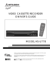
EXAMPLE OF ANTENNA GROUNDING
15. Outdoor Antenna Grounding
If an outside antennaor cablesystem isconnected to the TV receiver,be sure
the antenna or cable systemisgrounded so asto provide some
protection againstvoltage surgesand built-up static charges.
Section 810 of the National Electrical Code,ANSI/NFPA
70-1984,provides informationwith respect to proper
grounding of the mast and supporting structure, grounding
of the lead inwire to an antennadischarge unlt, size of
grounding conductors, location of antennadischargeunit,con-
nection to grounding electrodes, and requirements for the
grounding electrode.
LEADIN WIRE
{NEC SECTION 810-20)
GROUNDkNG
CONDUCTORS
=_POWE R SERVIC E GROUNDING
ELECTRODE SYSTEM
NEC -. NATkONAL ELECTRICAL CODE {NEC ART 250, PART H)
16. Servicing
Do not attempt to service this TV receiver yourself asopening or removing covers may expose you to
dangerousvoltage or other hazards. Refer all servicing to qualified service personnel.
17. Damage Requiring Service
Unplug this TV receiver from the wall outlet and refer servicing to qualified service personnel under the
following conditions:
(a)When the power-supply cord or plug is damaged.
(b) If liquid hasbeen spilled,or objects havefallen into theTV receiver.
(c) If theTV receiver hasbeen exposed to rain or water.
(d) If theTV receiver does not operate normally by following the operating instructions, adjust only those
controls that are covered by the operating instructions asan improper adjustment of other controls may
result in damageand will often require extensive work by a qualified technician to restore theTV receiver to
itsnormal operation.
(e) If theTV receiver hasbeen dropped or the cabinet hasbeen damaged.
(f)When the TV receiver exhibits a distinct changein performance -- this indicatesa need for service.
18. Replacement Parts
When replacement parts are required, be sure the service technician hasused replacement parts specified
by the manufacturer or havethe samecharacteristics asthe original part. Unauthorized substitutions may
result in fire, electric shock or other hazards.
19. Safety Check
Upon completion of anyservice or repairs to this TV receiver,askthe service technician to perform safety
checksto determine that the TV receiver isin safeoperating condition.

0 ComponentVideo Input - for the best picture from DVD players
0 DiamondShield TM- protective screen shield for modelsVS-50705,
VS-55705,VS-60705 andVS-70705
0 IRIS TM - sensor that automatically adjusts brightness and contrast, for
models VS-50705,VS-55705,VS-60705 andVS-70705
0 Multibrand Remote Control - use one remote control for many
audio video components
The following items are included with your newTV:
Remote C0ntr_
m II
2 AAA
batteries
The connections shown in this book are general. Cable systems as well as individual audio andlor
video components can vary from those shown here. The first diagram show basic connections
to antenna or cable systems. After you have completed these, you can then connect any addi-
tional components (stereo, DVD, AV receiver, etc.).
IMPORTANT
To maximize your system for its best
performance, your dealer can help you
customize hookups and sell you any
additional connection accessories that
may be needed for your individual
equipment.
7

0 Hooking up yourTV to an antenna or wall outlet cable
0 Remote control functions - pages 19-20
0 Menu screen summaries - page 22-24
0 Selecting the input - page 3 I
0 Setting theV-chip parent lock - page 33
0 Picture-in-picture mode - page 50
0 Picture-outside-picture mode
(forVS-50705,VS-55705,VS-60705 andVS-70705)
0Troubleshooting- page 57
- page 9
-p_e52

TV to Antenna orWall Outlet Cable
Separate UHF andVHF antennas
I, Connect the UHF andVHF
antenna leads to the UHF/VHF
combiner,
2, Press the combiner ontoANT-A
on theTV back panel.
VHF Antenna UHF A_ter _a
_3) (Channel 14_9)
Rat TwEn Le_d F_t TW_E_L_ad 1
1
External
A_t_a
or Ca_
OPTIONAL"
30_Ognrm t°
Bacl; Sole
TV Back Panel
ANT.A
®
00
O0
o
i
o o
@®@
®@@
o_, @o®
*there are different combiners for different wires.
Check with your dealer for the combiner style that you need.
Twin lead antenna or wall outlet cable
For antenna with twin fiat
leads
I, Connect the 300 ohm twin leads to
the transformer.
2. Push the 75 ohm side of the trans-
former onto ANT-A on theTV
back panel,
For cable or antenna with
coaxial lead
Connect the incoming cable to
ANT-A on the TV back panel,
fs Ohm ,
2°°.....L/
Twin Leaa
J
z
_o Ohm _ to 7_ Ohm out
Ma_r_i_g _r_ns_ormer
TV Back PaneI
o 6
@ @@
@@ @@
%e %o
®
Connection of TV to Cable Box
I, Connect the incoming cable to
ANT-A on the TV back panel.
2, Connect two coaxial cables as
follows:
• One from CABLE LOOP-OUT on
theTV back panel to IN on the
back of the cable box,
• One from OUT on the back of the
cable box to ANT-B on theTV
back panel,
TV Back Pane]
Incoming Ca_

Connection ofTV toVCR and Cable Box
I. Connect the incoming cable toANT-A
on theTV back panel.
2. Connect three coaxial cables as follows:
• One from CABLE LOOP-OUT on the
TV back panel to IN on the back of the
cable box.
• One from OUT on the back of the
cable box to ANTENNA IN on the
VCR back panel.
• One from ANTENNA OUT on the
VCR back panel to ANT-B on the TV
back panel.
C_BL_
ANTAL0_O0UT A_T B
®®
©
TV Back Pa_e_
,i@
® ® @
® ® ®
®o®
V6R Back Pa_l
If your VCR has a video channel
ONIOFF sw[tch_ set _tto OFF,
Audio Video Connections
I. Connect a video cable fromVIDEO
OUT on theVCR back panel toVIDEO
INPUT I or INPUT 2 on theTV back
panel.
If you have a S-VHS VCR, follow the
same steps, using the S-Video terminals
on the VCR and TV.
2. Connect a set of audio cables from
AUDIO OUT on theVCR back panel
to AUDIO INPUT on the TV back
panel. The red cable connects to the R
(right) channel and the white cable
connects to the L (left). If yourVCR is
non-stereo, connect only the L (left)
cable.
,@
®
o
®
TV B_ck Pane
°&
RCA
p[_ t pe
CabEe
VCR Back pa_e_
If your VCR has a video channel
ON/OFF switch, set it to OFF,
RCA pin t e
Attach
only
cablo
typ_
S-Video
_ype cable
10

Connection ofTV toVCR and Antenna or
Wall Outlet Cable
Antenna/Cable Connections
I, Connect the incoming cable toANT-A
on theTV back panel,
2, Connect two coaxial cables as follows:
• One from CABLE LOOP-OUT on the
TV back panel toANTENNA IN on the
VCR back panel,
• One fromVCR back panelANTENNA
OUT to ANT-B on the TV back panel,
If your VCR has a video channe{
ON/OFF switch, set it to OFF,
® ® i@ii@ @
_T A _JTA_T
®
Audio/Video Connections
I. Connect a video cable fromVIDEO
OUT on theVCR back panel toVIDE@
INPUT I or INPUT 2 on theTV back
panel.
If you have a S-VHS VCR, follow the
same steps, using the S-Video terminals
on the VCR and TV.
2. Connect a set of audio cables from
AUDIO OUT on theVCR back panel to
AUDIO INPUT on the TV back panel.
The red cable connects to the R (right)
channel and the white cable connects to
the L (left). If your VCR is non-stereo,
only connect the L (left) cable.
VCR Sack Panel
If your VCR has
a video channel
ON/OFF switch,
set it to OFF
®
II

Connection of TV to Stereo Audio System
I. Connect the audio cables from AUDIO
MONITOR OUTPUT on the TV back
panel toTV IN orAUX IN terminals on
the back of the audio system. The red
cable connects to the R (right) channel
and the white cable connects to the L
(left) channel.
2. Turn off the TV'S speakers through the AV
Connection Menu (page 27).
3. Set the audio system's input to theTV or
AUX position to hear the TV's audio
through your stereo system.
Audio _y_Lern teat tetrn_na_
TV Back Pa_e_
of _b
o @@
®
Connection of TV to the Active A/V Network
To control your Mitsubishi audio and/or video products with one remote control
Connect the A/V network cable from
ACTIVE A/V NETWORK on theTV
back panel to IN on the back of a
Mitsubishi component that hasA/V
network terminal.
IMPORTANT
Check the Owner's Guide of your
added Mitsubishi components to
ensure the best possible connections.
Mi_subishiCompone£treartermJnals
TV Back Panek
® @ ®
®® ® ® ®
@@@
ACTWEAN
N_TWORK
12

Connection of TV to AV Receiver
I. Connect a video cable from VIDEO
MONITOR OUT on the back of the AV
Receiver toVIDEO INPUT I on theTV
back panel using aVIDEO cable,
2, Connect a video cable fromVIDEO
MONITOR OUTPUT on the TV back
panel toVIDEOTV IN on the back of
the AV Receiver,
3, Connect a set of audio cables from
AUDIO OUTPUT on the TV back
panel to AUDIOTV IN on the back of
theAV Receiver. The red cable con-
nects to the R (right) channel and the
white cable connects to the L (left)
channel.
TV _ack paneE
®
AV RECEIVER
F_
F_JD-
13

Connection of TV to DVD with ComponentVideo
Outputs
IMPORTANT
For Digital Audio connections, see
the Owner's Guides of your DVD
Player and AV Receiver.
For ComponentVideo Connections
I. Connect the ComponentVideo cables
from VIDEO OUT on the back of the
DVD player to DVDVIDEO INPUT on
the TV back panel, matching the correct
components:
• Y toY,
Cr to Cr,
Cb to Cb.
2. Connect a set of audio cables from
AUDIO OUT on the back of the DVD
player to DVD AUDIO INPUT on the
TV back panel. The red cable connects
to the R (right) channel and the white
cable connects to the L (left) channel.
TV Back Panel
I 0
o
DVD Rear Terminal
Warning: Don't display the same stationary images on the screen for more than 15%of your total TV
viewing in one weelc Examples of stationary images are letterbox top/bottom bars from DVD disc or
other video sources, side bars when showing standard TV pictures on widescreen TV's, stock market
reports, video game patterns, station logs, web sites or stationary computer images. Such patterns can
unevenly age the picture tubes causing permanent damage to the TV. Please see page 58 for a detailed
explanation.
14

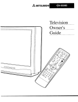
For Models VS-45605
and VS-50605
REC STOP PAUSE
REW/REV FF/FWD
PLAY
_ MITSUBISHI
light
Additional features of Models
VS-50705, VS-55705,VS-60705
and VS-70705
REC STOP PAUSE
REW/REV FF/FWD
pLAy
,_ MrrsuBISHI
GUIDE button
for DSSsystems
15

OperatingYour Remote Control
Installing the batteries
I. Removethe back cover of the remote control by pushingthe
the direction of the arrow and slidingoff the cover.
2.Load the batteries, makingsure the polarities(+) and (-) are correct.
IMPORTANT
When you replace the batteries in your remote
control, the remote may return to its initial
setting. You may need to set up your remote
again.
tab in
For best results
Be within 20 feet of the equipment when using the remote control.
Don't press two or more buttons at the same time, unless you are
specifically instructed to do so in this owner's guide.
Don't allow the remote control to get wet or become heated.
Avoid dropping the remote control on a hard surface.
When cleaning the remote control, don't use any harsh chemicals.
Use only a soft, slightly moistened cloth.
Don't mix new batteries with old ones.
Don't heat, take apart, or throw batteries into a fire.
Use alkaline batteries.
Using the remote control with yourTV
You can use your remote to control the TV, CABLE/DBS,VCR,
DVD or AUDIO. The remote has been preset to operate the
TV and other Mitsubishi products. It can be set to control
other audio/video equipment.
To operate the TV, the select switch at the top of the remote
should be set toTV.
16
I_
C_LE/DB$ VGR DVD
ooo 0
O O 0
O O 0

Remote Control of Other Audio and Video Products
Programming the Remote to Control OtherAudio andVideo Products:
Move the slide switch at the top of the remote to select the
audio or video product you want to control.
Press and hold the POWER button, so that it stays down when
you enter the code.
Enter the code for the equipment from the appropriate list,
exactly asstated. If there is more than one code number, start
with the first number. After setting the code, release the
POWER button.
Point the remote at the equipment and press the POWER
button. If it is on and turns off or is off and turns on, the
remote will control the equipment. If not, try the next number.
Cable Box codes:
Cable box brand codeto enter: If your
General Instruments/ 111,119, 120, 121,122, cable box
Jerrold 123, 124, 125, 126, 127 code is not
Oak 102, 137, 139 listed here,
please see
Pioneer 101, 116 page 63
Scientific Atlanta 111,112,113 for a
Zenith 100, 117 complete
To reset to default code, enter 000 listing,
Satellite Receiver codes:
VCR
CABLE/DeS DVD
Tv.ll Aoo,o
I M PO RTA NT
If you cannot turn the cable box ON by
pressing POWER, try pressing the
CHANNEL or the number buttons.
Satellite brand
Dishnetwork
Hughes-DSS
RCA-DSS
Sony-DSS 177
Toshiba-DSS 170
Panasonic-DSS 174
Pdmestar 178
To reset to default
codeto enter:
175 "
173
176
code, enter 000
VCR codes:
VCR brand codeto enter:
If your
Mitsubishi 001,002 VCR
Hitachi 020, 043, 065 code is not
JVC 030, 054,059 listed here,
Philips/Magnavox 043,044, 051 please see
Panasonic 041,042, 043 page 64
RCA 020, 053, 065 for a
Sony 048,049, 050 complete
Toshiba 021,066 listing.
TO reset to default code, enter 000
If your
satellite
code is not
listed here
)lease see
page 63
for a
complete
listing,
VCR
CABLE/DBS OVD
VCR
CABLE/DeS
I M PO RTA NT
When set to TV, the PLAY, STOP, REW/
REV and the FF/FWD keys will operate
theVCR after theVCR codes have been
chosen.
17

Remote Control of Other Audio and Video Prod-
uct, continued
DVD Player codes:
DVD/LDP brand
Mitsubishi (DVD)
Mitsubishi (LDP)
Panasonic
Pioneer DVD (LDP)
Sony
Toshiba
codeto enter:
003
016, 017
250
252 (016,017)
254
253
To reset to default code, enter 000
If your
DVD code
is not
listed here,
please see
page 63
for a
complete
listing.
VCR
CABLE/DaS
TV
AV Receiver codes:
Audio brand
Mitsubishi AV receiver
Mitsubishi CD player
Kenwood
Onkyo
Pioneer
Sony
Yamaha
code_ en_r:
010,011,012
013,014,015
200,208
209,214
205,207
222
201,202
To reset to default code, enter 000
If your
Audio
code isnot
listed here,
please see
page 63
for a
complete
listing.
VCR
CABLE/DBS DVD
TV
IMPORTANT
If the slide switch isset toTV when you
enter an AV receiver code,VOLUME and
MUTE will be controlled by theAV receiver.
18
Additional slide switch feature:-for multiple AJV component systems
Your Mitsubishi remote control was designed for flexibility in both large and smallA/V systems.
For example, you can use the slide switch in the following way:
If you have twoVCR's, but no DVD player, move the slide switch to the DVD position and enter
the secondVCR code. Then when the slide switch is moved to DVD you can control the second
VCR.
The following chart shows which device can be entered for each position. Only one device is
allowed for each slide switch position.
TV position:
• TV
• any A/V receiver
(volume, mute only)
Cable/DBS position:
• cable box
• satellite receiver
VCR position: Audio position:
• any VCR • anyAV receiver
• Mitsubishi DVD • Mitsubishi CD player
player • cable box
DVD position:
• any DVD
• any VCR
• cable box
I[ IM PORTANT
/ Some manufacturers may change their products, or they may
J use more than one remote control system. If this isthe case,
your remote_maY -not be able to operate yourVCR, Cable Box,
.................................

Remote Control Functions
Select switch
Selects which AN
wilt be controlled by the
remote
Numbers
To individually select
channels or enter
information into TV
SQV (SuperQuickView TM)
Scan through a memorized list of
favorite channels
Power
power on and off for theTV
or otherAN products
QV (QuickView)
-- Switchesto last channelviewed
INPUT
Selectsthe signalyou will watch (Ant
A; Ant B;Input I, 2 or 3; DVD)
CHANNEL
View channelsin increasingor
decreasingnumerical order
VOLUME
Increasesordecreasessound
©0
SLEEP
Sets theTV to turn off
within 2 hours
VIDEO
Individually adjuststheVideo
settings
AUDIO
Adualtyadjusts
the Audio settings
MUTE
rurnsonoroffthesound
19

Remote Control Functions, continued
ENTER
Use after selecting a
channel number or
menu item
LIGHT
For VS-50705,VS-55705,VS-60705
and VS-70705, press to light up
the remote control
CANCEL
Clear SQV and some
menu entries
PIP or PIP/POP
Useto display,move,
resize or changea PIP
channel.ForVS-50705,
VS-55705,VS-60705and
VS-70705 useto display,
resize or changea POP
channel
ooo 0
OOO
OOO
GO0 _
J
ADJUST
Selects menu items.
Moves the PIP
on-screen location
GUIDEFor VS-S0705,VS-SS705,
VS-60705 andVS-70705.
satellite systems program
guides
MENU
Displays on-screen menu
choices
HOME
Exit on-screen menusand
return to TV viewing
INFO
Displays an on-screen
summary of currentTV
settings
REC
Manually record
programs on your VCP_,_
REW/REV
Rewind and reverse search for
theVCR. Skip reverse for CD.
Reverse scan for DVD
PLAY
PlaysaVCR,
N
OOOo
000
000
000 _
JJJ
STOP
Tostop aVCR, DVD or
PAUSE
_Temporarity stops a
VCR, DVD or CD or
freezes the PIP/POP
FF/FWD
ast forward or forward search
for aVCR. Skip forward for a CD.
Fast play for a DVD
20
/