Page is loading ...

36" & 48" Shutter Box Fan
Installation & Operator’s Instruction Manual
Mv1666-005 12/00
MV1666BFebruary 2004

Chore-Time Warranty 36" & 48" Shutter Box Fan
2
MV1666B
Chore-Time Equipment (“Chore-Time”) warrants each new Chore-Time product manufactured by it to be free
from defects in material or workmanship for one year from and after the date of initial installation by or for the
original purchaser. If such a defect is found by the Manufacturer to exist within the one-year period, the
Manufacturer will, at its option, (a) repair or replace such product free of charge, F.O.B. the factory of
manufacture, or (b) refund to the original purchaser the original purchase price, in lieu of such repair or
replacement. Labor costs associated with the replacement or repair of the product are not covered by the
Manufacturer.
Conditions and Limitations
1. The product must be installed by and operated in accordance with the instructions published by the
Manufacturer or Warranty will be void.
2. Warranty is void if all components of the system are not original equipment supplied by the Manufacturer.
3. This product must be purchased from and installed by an authorized distributor or certified representative
thereof or the Warranty will be void.
4. Malfunctions or failure resulting from misuse, abuse, negligence, alteration, accident, or lack of proper
maintenance shall not be considered defects under the Warranty.
5. This Warranty applies only to systems for the care of poultry and livestock. Other applications in industry
or commerce are not covered by this Warranty.
The Manufacturer shall not be liable for any Consequential or Special Damage which any purchaser may suffer
or claim to suffer as a result of any defect in the product. “Consequential” or “Special Damages” as used herein
include, but are not limited to, lost or damaged products or goods, costs of transportation, lost sales, lost orders,
lost income, increased overhead, labor and incidental costs and operational inefficiencies.
THIS WARRANTY CONSTITUTES THE MANUFACTURER’S ENTIRE AND SOLE WARRANTY AND
THIS MANUFACTURER EXPRESSLY DISCLAIMS ANY AND ALL OTHER WARRANTIES,
INCLUDING, BUT NOT LIMITED TO, EXPRESS AND IMPLIED WARRANTIES AS TO
MERCHANTABILITY, FITNESS FOR PARTICULAR PURPOSES SOLD AND DESCRIPTION OR
QUALITY OF THE PRODUCT FURNISHED HEREUNDER.
Chore-Time Distributors are not authorized to modify or extend the terms and conditions of this Warranty in any
manner or to offer or grant any other warranties for Chore-Time products in addition to those terms expressly
stated above. An officer of CTB, Inc. must authorize any exceptions to this Warranty in writing. The Manufacturer
reserves the right to change models and specifications at any time without notice or obligation to improve previous
models.
Effective: February 2004
Chore-Time Equipment
A Division of CTB, Inc.
P.O. Box 2000 • Milford, Indiana 46542-2000 • U.S.A.
Phone (574) 658-4101 • Fax (877) 730-8825
Email: [email protected] • Internet: http//www.ctbinc.com
Thank You
The employees of Chore-Time Equipment would like to thank your for your recent Chore-Time purchase. If a
problem should arise, your Chore-Time distributor can supply the necessary information to help you.
Chore-Time Warranty

Contents
Topic Page User
MV1666B
* Legend: C = Customer (end user), D = Distributor (sales), I = Installer of equipment
3
Chore-Time Warranty . . . . . . . . . . . . . . . . . . . . . . . . . . . . . . . . . . . . . . . . . . . . . . . . 2 C,D
General. . . . . . . . . . . . . . . . . . . . . . . . . . . . . . . . . . . . . . . . . . . . . . . . . . . . . . . . . . . . . 4 C,D,I
Support Information . . . . . . . . . . . . . . . . . . . . . . . . . . . . . . . . . . . . . . . . . . . . . . . . . . . . . . .4
Distributor and Installer Information . . . . . . . . . . . . . . . . . . . . . . . . . . . . . . . . . . . . . . . . . .4
About This Manual. . . . . . . . . . . . . . . . . . . . . . . . . . . . . . . . . . . . . . . . . . . . . . . . . . . 5 C,D,I
Safety Information . . . . . . . . . . . . . . . . . . . . . . . . . . . . . . . . . . . . . . . . . . . . . . . . . . . 5 C,D,I
Safety–Alert Symbol. . . . . . . . . . . . . . . . . . . . . . . . . . . . . . . . . . . . . . . . . . . . . . . . . . . . . . .5
Understanding Signal Words . . . . . . . . . . . . . . . . . . . . . . . . . . . . . . . . . . . . . . . . . . . . . . . .5
Follow Safety Instructions . . . . . . . . . . . . . . . . . . . . . . . . . . . . . . . . . . . . . . . . . . . . . . . . . .6
Decal Descriptions . . . . . . . . . . . . . . . . . . . . . . . . . . . . . . . . . . . . . . . . . . . . . . . . . . . . . . . .6
DANGER: Electrical Hazard . . . . . . . . . . . . . . . . . . . . . . . . . . . . . . . . . . . . . . . . . . . .6
Technical Information . . . . . . . . . . . . . . . . . . . . . . . . . . . . . . . . . . . . . . . . . . . . . . . . 7 C,D,I
Tools Required . . . . . . . . . . . . . . . . . . . . . . . . . . . . . . . . . . . . . . . . . . . . . . . . . . . . . . . . . . .7
Fan Assembly Procedure . . . . . . . . . . . . . . . . . . . . . . . . . . . . . . . . . . . . . . . . . . . . . . 8 C,I
Step 1 - Secure Motor Mount Post to Fan Shroud . . . . . . . . . . . . . . . . . . . . . . . . . . . . . . . .8
Step 2 - Mount Side Panels to Fan Shroud . . . . . . . . . . . . . . . . . . . . . . . . . . . . . . . . . . . . . .9
Step 3A - (Direct Drive) Assembly Procedures . . . . . . . . . . . . . . . . . . . . . . . . . . . . . . . . . 10
Motor Assembly . . . . . . . . . . . . . . . . . . . . . . . . . . . . . . . . . . . . . . . . . . . . . . . . . . . . . 10
Blade Assembly. . . . . . . . . . . . . . . . . . . . . . . . . . . . . . . . . . . . . . . . . . . . . . . . . . . . . . 10
Step 3B - (Belt Drive Assembly Procedures) . . . . . . . . . . . . . . . . . . . . . . . . . . . . . . . . . . . 11
Motor Mount Assy. to Posts . . . . . . . . . . . . . . . . . . . . . . . . . . . . . . . . . . . . . . . . . . . 11
Securing the Module Assembly and Motor. . . . . . . . . . . . . . . . . . . . . . . . . . . . . . . . . 11
Motor Sheave and Belt Installation. . . . . . . . . . . . . . . . . . . . . . . . . . . . . . . . . . . . . . . 12
Sheave Mounting . . . . . . . . . . . . . . . . . . . . . . . . . . . . . . . . . . . . . . . . . . . . . . . . . . . . . 13
Belt Alignment . . . . . . . . . . . . . . . . . . . . . . . . . . . . . . . . . . . . . . . . . . . . . . . . . . . . . . 14
Fan Blade Installation . . . . . . . . . . . . . . . . . . . . . . . . . . . . . . . . . . . . . . . . . . . . . . . . . 15
Step 4 - Screen Installation . . . . . . . . . . . . . . . . . . . . . . . . . . . . . . . . . . . . . . . . . . . . . . . . . 16
Step 5 - Shutter Louver Installation . . . . . . . . . . . . . . . . . . . . . . . . . . . . . . . . . . . . . . . . . . 17
Shutter Louver Installation Continued..... . . . . . . . . . . . . . . . . . . . . . . . . . . . . . . . . . . 18
(Optional) Mounting Kit. . . . . . . . . . . . . . . . . . . . . . . . . . . . . . . . . . . . . . . . . . . . . . . . . . . 18
Fan Installation . . . . . . . . . . . . . . . . . . . . . . . . . . . . . . . . . . . . . . . . . . . . . . . . . . . . . . 19 C,D,I
Wiring. . . . . . . . . . . . . . . . . . . . . . . . . . . . . . . . . . . . . . . . . . . . . . . . . . . . . . . . . . . . . . . . . 19
Maintenance . . . . . . . . . . . . . . . . . . . . . . . . . . . . . . . . . . . . . . . . . . . . . . . . . . . . . . . . 19 C
Shutter Fan Specification. . . . . . . . . . . . . . . . . . . . . . . . . . . . . . . . . . . . . . . . . . . . . . 20 C,D,I
Itemized Parts and Listing: 36" DD Shutter Fan . . . . . . . . . . . . . . . . . . . . . . . . . . 21 C,D,I
Parts Listing: 48" BD Shutter Fan . . . . . . . . . . . . . . . . . . . . . . . . . . . . . . . . . . . . . . 22 C,D,I
Itemized Parts: 48" Belt Drive Shutter Fan. . . . . . . . . . . . . . . . . . . . . . . . . . . . . . . 23 C,D,I

General 36" & 48" Shutter Box Fan
4
MV1666B
Support Information
The Chore-Time Shutter Fans are designed to be used as exhaust fans. The Shutter Fans are shipped unassembled
to save on shipping charges. Using this equipment for any other purpose or in a way not within the operating
recommendations specified in this manual will void the warranty and may cause personal injury.
This manual is designed to provide comprehensive planning, installation, safety, operation, and parts listing
information. The Table of Contents provides a convenient overview of the information in this manual. The Table
of Contents also specifies which pages contain information for the sales personnel, installer, and consumer (end
user).
Distributor and Installer Information
General
Please fill in the following information about your Product.
Keep this manual in a clean, dry place for future reference.
Distributor’s Name___________________________________________________
Distributor’s Address ________________________________________________
Distributor’s Phone _______________________ Date of Purchase ___________
Installer’s Name _____________________________________________________
Installer’s Address___________________________________________________
Installer’s Phone _______________________ Date of Installation ___________
System Specifications________________________________________________
___________________________________________________________________

36" & 48" Shutter Box Fan About This Manual
MV1666B
5
The intent of this manual is to help you in two ways. One is to follow step-by-step in
the order of assembly of your product. The other way is for easy reference if you have
questions in a particular area.
Important ! Read ALL instructions carefully before starting construction.
Important ! Pay particular attention to all SAFETY information.
• Metric measurements are shown in millimeters and in brackets, unless otherwise
specified. “ " ” equals inches and “ ' ” equals feet in English measurements.
Examples:
1" [25.4]
4' [1 219]
• Optional equipment contains necessary instructions for assembly or operation.
• Major changes from the last printing will be listed on the back cover.
• This Planning Symbol is used in areas where planning needs to take place before
construction continues.
• Very small numbers near an illustration (i.e., 1257-48) are identification of the
graphic, not a part number.
Caution, Warning and Danger Decals have been placed on the equipment to warn
of potentially dangerous situations. Care should be taken to keep this information
intact and easy to read at all times. Replace missing or damaged safety decals
immediately.
Using the equipment for purposes other than specified in this manual may cause
personal injury and/or damage to the equipment.
Safety–Alert Symbol
This is a safety–alert symbol. When you see this symbol on your equipment, be alert
to the potential for personal injury. This equipment is designed to be installed and
operated as safely as possible...however, hazards do exist.
Understanding Signal Words
Signal words are used in conjunction with the safety–alert symbol to identify the
severity of the warning.
DANGER indicates an imminently hazardous situation which, if not avoided, WILL
result in death or serious injury.
WARNING indicates a potentially hazardous situation which, if not avoided,
COULD result in death or serious injury.
CAUTION indicates a hazardous situation which, if not avoided, MAY result in
minor or moderate injury.
About This Manual
Safety Information

Safety Information 36" & 48" Shutter Box Fan
6
MV1666B
Follow Safety Instructions
Carefully read all safety messages in this manual and on your equipment safety signs.
Follow recommended precautions and safe operating practices.
Keep safety signs in good condition. Replace missing or damaged safety signs.
Decal Descriptions
DANGER: Electrical Hazard
Disconnect electrical power before inspecting or servicing equipment unless
maintenance instructions specifically state otherwise.
Ground all electrical equipment for safety.
All electrical wiring must be done by a qualified electrician in accordance with local
and national electric codes.
Ground all non-current carrying metal parts to guard against electrical shock.
With the exception of motor overload protection, electrical disconnects and over
current protection are not supplied with the equipment.
DANGER: Rotating Fan Blade
This decal is placed on the Panel Weldment.
Severe personal injury will result, if the electrical power is not disconnected, prior to
servicing the equipment.
Safety Information

36" & 48" Shutter Box Fan Technical Information
MV1666B
7
The diagram below shows the proper location of the safety decal (DANGER--
ROTATING FAN BLADE) as shipped from the factory. Replace damaged or
missing decals. Make sure the decals may be easily seen at all times.
If the fan is purchased unassembled, the Chore-Time Fan Assembly Part Number
Decal will be packed with this instruction manual. Make sure the decal location
shown below is clean and dry. Remove the backing of the decal and affix it to the Fan
Shroud.
Motor choices and specifications are provided in the Parts List section of this manual.
See page 20 for Fan Motor specifications.
Important Chore-Time Equipment strongly recommends that a good alarm system
should be installed in confinement buildings to warn of power failure
and high temperature.
Chore-Time Equipment also recommends that an alternate power source be available
for confinement buildings in case of power failure.
Tools Required
• Hammer
• 1/2” Open End Wrench or Socket Wrench with 1/2” Socket
• Wire Cutters & Strippers
• Adequate Size & Quantity of Electrical Wire
• 5/16” Hex Key Wrench
• 5/16” Open End Wrench or a 12 Point 3/8” Socket and Ratchet
Mv1666-001 12/00
Figure 1. Decal Placement
Technical Information

Fan Assembly Procedure 36" & 48" Shutter Box Fan
8
MV1666B
For Factory Assembled Fans see Steps 3 through 6.
Step 1 - Secure Motor Mount Post to Fan Shroud
Secure the Motor Mount Post to the Fan Shroud using the 5/16-18 x 5/8'' carriage
bolts and hex nuts provided in the Hardware Package
The Motor Mount Post must be installed as shown in Figure 2.
Fan Assembly Procedure
36" 48"
Mv1666-002 12/00
1
2
4
1
2
3
4
2
3
4
Key Description
1 Fan Shroud
2 Motor Mount Post
3 5/16-18 x 5/8'' Carriage Bolt
4 5/16-18 Serrated Nut
Figure 2. Motor Mount Installation

36" & 48" Shutter Box Fan Fan Assembly Procedure
MV1666B
9
Step 2 - Mount Side Panels to Fan Shroud
The Side Panels for the Box Fans are identical. The Panels lock together by inserting
the tabs of one Panel into the slot in the end of another Panel (See Figure 3).
Orienting the Side Panels as shown in Figure 3, assemble the Side Panels together
around the Shroud using the 5/16-18 hardware provided.
36'' Fans use (2) bolts and nuts per side. 48" Fans use (3) bolts and nuts per side to
attach shroud.
Use a hammer to carefully bend the corner tabs over to secure the Side Panels
together.
Note: Orient the Shroud with the Shroud Drain Holes at the bottom of the Fan.
Remove the (2) Knockouts from the bottom Side Panel for water
drainage.
Mv1666-003 12/00
3
1
2
4
6
7
5
8
1
Figure 3. Mounting Side Panels to shroud
Item Description Item Description
1 Side Panel 6 Lock Side Panels together by bending tabs over.
2 Fan Shroud 7 Shroud Drain Holes
3 5/16-18 x 5/8'' Carriage Bolt 8 Shroud Orifice
4 5/16-18 Serrated Nut
5 Knockouts

Fan Assembly Procedure 36" & 48" Shutter Box Fan
10
MV1666B
Step 3A - (Direct Drive) Assembly Procedures
Motor Assembly
Blade Assembly
3
1
2
Mv1666-010 01/01
Item Description
1 Motor Support
2 Motor
3 #10-32 Serrated Flange Nut
Mv1666-011 01/01
3
4
2
1
Item Description
1 Blade Assembly
2 Fan Blade Hub
3 Motor
4 Motor Shaft With Key/Keyway
and Flat

36" & 48" Shutter Box Fan Fan Assembly Procedure
MV1666B
11
Step 3B - (Belt Drive Assembly Procedures)
Motor Mount Assy. to Posts
Note: The Shutter Fans may be ordered with or without the Motor.
If a Factory Assembled Fan was ordered, the Fan Blade was shipped mounted to a
Shipping Bracket. The Shipping Bracket must be removed and
discarded. (See Figure 4)
Securing the Module Assembly and Motor
Secure the Module Assembly and Motor between the Motor Support Posts
(Item 5, Figure 5). Hardware is included in the Hardware Package.
If your Fans do not have factory-included motors, set the Motor on the Module
Assembly and secure in place with the 5/16-18 x 5/8'' carriage bolts, and 5/16''-18
Serrated Flange nuts. (See Figure 5)
The Motor is mounted in the rear set of holes.
1
2
Mv1666-017 01/01
Item Description
1 Fan Blade
2 Shipping Bracket
Figure 4. Detail of Shipping Bracket on Factory Assembled Fans (For Belt Drive Units Only)
1
2
2 1
4
3
Mv1666-004 12/00
5
Key Description Part
No.
1 5/16''-18 Hex Serr. Flange Nut 8490
2 5/16''-18 Carriage Bolt 8282
3 Module Assembly 45581
4 Motor Mount Assembly (BD) 45698
5 Motor Support Post 43688
Figure 5. Fan Module and Motor Installation

Fan Assembly Procedure 36" & 48" Shutter Box Fan
12
MV1666B
Motor Sheave and Belt Installation
1
3
4
6
2
7
5
8
MV1645-006 10/00
9
11
10
MV1645-005 10/00
Item Description Part Numbers
1 Motor Varies
2 Spring (Compress to 2-1/4'') 43715
3 Pivot Motor Mount Plate 43713
4 Pivot Plate Mounting Bracket 43714
5 Z-Motor Mounting Bracket 43712
6 Bolt, 5/16-18 x 5.5'' 4412-21
7 Spring Cap (2 pcs) 44002
8 5/16'' Flange Nut 2148
9 5/16'' Flat Washer 546
10 5/16-18 x .625'' Carriage Bolt 8282
11 5/16-18" Flange Nut 8490
Mount the Motor
(Item 1, Figure 6)
to the Pivot Motor Mount Plate
(Item 3, Figure 6)
by using the supplied
5/16-18 x .625'' Carriage Bolt (Item 10, Figure 6) with the heads coming up from the bottom and the 5/16-18''
Flange Nut (Item 11, Figure 6) on top.
Motor position before putting Belt on Sheave
and Pulley. Notice the bolt (Item 10) position.
Figure 6. Motor Installation
Rear View of Motor Installation

36" & 48" Shutter Box Fan Fan Assembly Procedure
MV1666B
13
Sheave Mounting
Apply Anti Seize to Motor Shaft (Item 3, Figure 7). Slide the Sheave onto the motor
shaft as shown. Insert the key provided with the motor as shown in Figure 7. to lock
the Sheave in place. Once the belt has been aligned, torque the set screw to 150-165
in-lbs to secure Sheave in place. (Do not tighten set screw until the belt is aligned.)
1
3
2
MV1601-008 11/00
Item Description
1 Sheave
2 Key
3 Anti-Seize
Figure 7. Sheave Mounting and Key Assembly.

Fan Assembly Procedure 36" & 48" Shutter Box Fan
14
MV1666B
Belt Alignment
• Belt must be vertical to obtain maximum Belt Life.
• Measure from a straight edge to the belt to make sure that there is equal dis-
tance. (See Figure 8)
IMPORTANT! Figure 8. indicates the proper items to check to insure best installation
and Fan life.
The spring is to be compressed to 2-1/4''. (Item 1 Figure 8)
3
4
Mv1666-019 01/01
1
2
5
Mv1666-020 01/01
Belt Alignment
Item Description
1 Spring Compression to 2-1/4''.
2 Install Belt as shown.
3 Straight edge
4 Measure from straight edge to belt.
5
Frame to belt measurement to be the
same at motor and driven sheaves.
Figure 8. Belt Alignment

36" & 48" Shutter Box Fan Fan Assembly Procedure
MV1666B
15
Fan Blade Installation
Slide the Fan Blade Assembly onto the shaft. The Hub of the Fan Blade should be
flush with the end of the Shaft (See Figure 9). Apply grease or an anti-seize
compound to the Fan Shaft before mounting the Fan Blade.
Insert key into keyway on shaft.
Tighten the set screw(s) using a 5/16'' open end wrench or 12 point 3/8'' socket and
ratchet).
Torque the set screws to approximately 150 in./lbs (12.5 ft/lbs).
IMPORTANT! If Decals are not already installed, see the Decal placement instructions
on page 7.
Mv1666-009 12/00
4
2
1
3
Item Description
1 Blade Assembly
2 Torque to 150 in/lbs (12.5 ft/lbs)
3 Shaft with Keyway
4 Fan Blade Hub Flush with Shaft
Figure 9. Blade Assembly Installation

Fan Assembly Procedure 36" & 48" Shutter Box Fan
16
MV1666B
Step 4 - Screen Installation
DANGER! The Wire Inlet Screen MUST be installed to prevent serious injury or
death.
The Wire Inlet Screen has an opening to accommodate the Motor and Motor
Mounting. Position the Wire Inlet Screen over the back of the fan with the screens
natural bow out away from the fan.
Install (4) Wire Clips on each side to secure the Wire Inlet Screen to the Side Panels.
See Figure 11.
1
2
Mv1666-006 12/00
Item Description
1 Motor Module
2 Wire Inlet Screen
Figure 10. Positioning the Wire Inlet Screen to fit the Motor and Motor Module
(Blade and Posts not shown for Clarity)
MV1544-3B 8/99
1
2
3
4
Figure 11. Screen Installation
Item Description
1 Screen Clip Part Number 38891
2 Wire Screen Part Numbers (36") 36629, and (48") 45865
3 Slip Screen Clip over Screen Wire.
4 Snap in slot on Fan Side Panel to secure.

36" & 48" Shutter Box Fan Fan Assembly Procedure
MV1666B
17
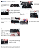
Step 5 - Shutter Louver Installation
Orient the Shutter Fan Assembly so that the drain holes are on the bottom. Insert the
tab on the end of one of the Center Rails into the slot on the Bottom Side Panel. Slide
the top of the Center Rail until it snaps into the corresponding slot in the Top Side
Panel. Repeat for the other Center Rail. (See Figure 12)
Insert a Shutter Pivot Rod in the second hole up from the bottom of the Center Rails,
through a Shutter Louver, and into the second hole up from the bottom on the Side
Panel. (See Figure 13)
MV1544-5A 8/99
1
2
2
3
Item Description
1 Bottom Side Panel
2 Center Rail
3 Slot for Center Rail
Figure 12. Installing Center Rails
Mv1666-008 01/01
2
1
3
4
5
Figure 13. Installing the first Shutter Louver
Item Description
1 Side Panel
2 Shutter Louver
3 Center Rails
4 Bottom Side Panel
5 Shutter Pivot Rod

Fan Assembly Procedure 36" & 48" Shutter Box Fan
18
MV1666B
Shutter Louver Installation Continued....
Slide the next Shutter Louver on the opposite end of the Shutter Pivot Rod, Bend the
Shutter Pivot Rod - Shutter Louver combination and insert the free end of the Shutter
Pivot Rod into the second hole up from the bottom of the other Side
Panel. (See Figure 14)
Repeat these steps for the remaining Shutter Pivot Rods and Shutter Louvers.
(Optional) Mounting Kit
Figure 15 shows the optional Mounting Kit available through your local dealer.
1
2
3
4
1
5
Mv1666-015 01/01
Item Description
1 Shutter Louver
2 Center Rails
3 Shutter Pivot Rod
4 Bottom Side Panel
5 Side Panel
Figure 14. Installing the second Shutter Louver
1
2
1
2
3
Mv1666-018 01/01
36'' Shutter Fan Mounting Kit Part Number 44456
1 Top 36'' Shutter Fan Mount 44402
2 Side 36'' Shutter Fan Mount 44403
3 Mounting Kit Package Hardware 44506
48'' Shutter Fan Mounting Kit Part Number 44455
1 Top 36'' Shutter Fan Mount 44400
2 Side 36'' Shutter Fan Mount 44401
3 Mounting Kit Package Hardware 44507
Figure 15. Optional Mounting Kit

36" & 48" Shutter Box Fan Fan Installation
MV1666B
19
Build fan framing out of 2'' (50 mm) lumber (not supplied). The required wall opening is
provided in the chart below. See Figure 16.
Insert and secure the Fan Assembly in the framed opening in the side wall (hardware not
supplied).
Wiring
See wiring diagram on Motor for Motor electrical connections. Follow local, state and
national electric codes for wiring.
Install an electric disconnect within reach of each Fan.
Service and maintenance of fans should be done only by a qualified technician.
DANGER! DISCONNECT POWER PRIOR TO MAINTAINING OR CLEANING THE FAN!
The fan may start automatically causing serious injury or death.
Keep the fan clean for maximum life and best performance. Do not spray water on Fan
Shaft Bearings.
Periodically check the V-Belt. If necessary, adjust the spring tension to prevent the belt
from slipping.
The Motor and Fan Shaft Bearings are permanently lubricated. Grease Zerks are provided
on the Fan Shaft Bearings when relubrication is needed. Relubrication is required
whenever water comes in contact with the Fan Shaft Bearings. Slowly rotate the Fan
Shaft as bearing is filled with Grease. Use only high quality lithium soap base grease and
clean all dirt from Zerk before applying grease.
Fan Installation
Mv1089-1a 8/99
A
B
Dimension
(minimum)
A B
36'' Fan 42-1/4''
[107.3 cm]
42-1/4''
[107.3 cm]
48'' Fan 54-5/8''
[138.7 cm]
54-5/8''
[138.7 cm]
Figure 16. Framing Diagram (front view)
Maintenance

Shutter Fan Specification 36" & 48" Shutter Box Fan
20
MV1666B
Shutter Fan Specification
Assembled
Fans
Unassembled
Fans
Electrical
Fan Description Fan Part No. Fan Part No. Volt HZ Phase
HP Motor Motor Sheave
Part No.
36" Direct Drive
Shutter Fans
44453-3620 115/230 60 1 1/2 28936 N/A
44453-3640 208-230/460 60 3 1/2 42098 N/A
41134-4820 40921-4820 230 60 1 1 37729 35333
48" Belt Drive 41134-4830 40921-4830 230 50 1 1 37729 8773
Shutter Fans 41134-4840 40921-4840 208-230/460 60 3 1 40157 35333
41134-4850 40921-4850 220-240/380-415 50 3 1 36142 24697
41134-4860 40921-4860 230/380-415 60 3 1 36142 35333
/