13
Bentone B40 MF/B45-2 MF
General
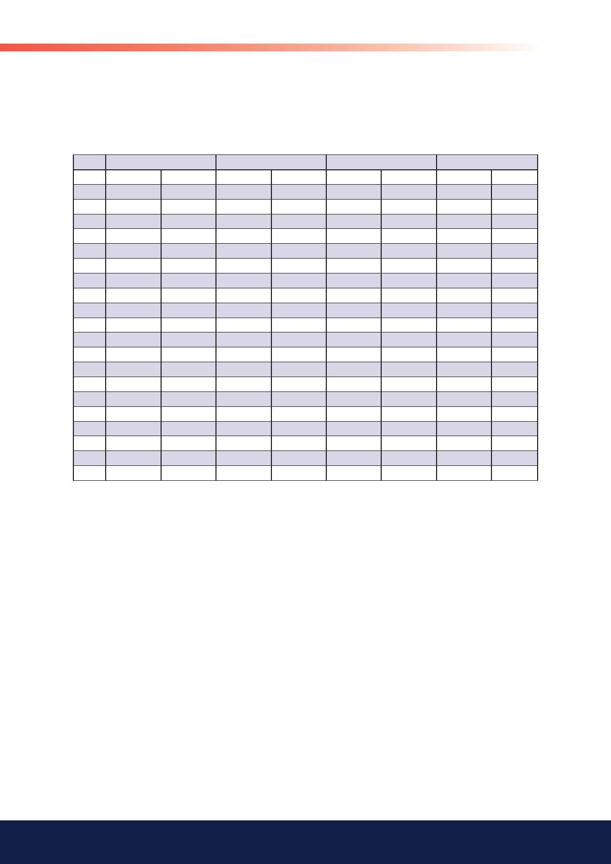
1.10 Nozzle for fossil oils, 22-28 bar
Pump pressure bar
The table applies to oil with a viscosity of 4.4 mm 2/s at a density of 830 kg/m 3.
Gph 22 24 26 28
kg/h kW kg/h kW kg/h kW kg/h kW
1,00 5,52 65,44 5,76 68,35 6 71,14 6,22 73,83
1,50 8,66 102,73 9,05 107,3 9,42 111,68 9,77 115,9
2,00 11,01 130,53 11,5 136,33 11,96 141,9 12,42 147,25
2,50 13,78 163,42 14,39 170,69 14,98 117,66 15,55 184,37
3,00 17,21 204,06 17,97 213,13 18,7 221,83 19,41 230,21
3,50 19,13 226,93 19,89 237,02 20,8 246,7 21,59 256,01
4,00 21,06 249,8 22 260,9 22,9 271,56 23,76 281,81
4,50 23,88 283,22 24,94 295,81 25,96 307,89 26,94 319,51
5,00 27,44 325,44 28,66 339,91 29,83 353,79 30,96 367,14
5,50 31 367,66 32,38 384 33,7 399,68 34,97 414,77
6,00 34,71 411,63 36,25 429,94 37,73 447,49 39,16 464,39
6,50 38,71 459,13 40,43 479,55 42,08 499,13 43,67 517,97
7,00 41,38 490,8 43,22 512,62 44,99 533,55 46,69 553,69
7,50 44,2 524,22 46,17 547,53 48,05 569,89 49,86 591,4
8,00 46,72 554,12 48,8 578,76 50,79 602,4 52,71 625,14
8,50 49,1 582,27 51,28 608,16 53,37 632,99 55,39 656,89
9,00 52,51 622,73 54,84 650,42 57,08 676,98 59,24 702,53
10,00 55,92 663,19 58,4 692,68 60,79 720,96 63,08 748,18
11,00 63,04 747,63 65,84 780,87 68,53 812,76 71,12 843,44
12,00 70,75 839,1 73,9 876,41 76,91 912,2 79,82 946,63