Page is loading ...

Providing sustainable energy solutions worldwide
178 139 15-1 2019-08-29
Installation- and maintenance instruction
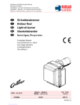
ST 120 KA

2Bentone
example Beispielexempel

3 Bentone
General
Table of contents
1. General Information __________________________________ 4
2. Technical data _______________________________________ 7
2.1 Dimensions ST 120 _______________________________ 7
2.2 Dimensions, flanges _______________________________ 8
2.3 Burner installation _________________________________ 8
2.5 Working field ST 120KA ____________________________ 9
2.4 Setting of brake plate and air flow ___________________ 9
2.6 Recommended nozzles and pressures ______________ 10
2.7 Nozzle table, 8-15 bar ____________________________ 10
2.8 Description ______________________________________ 11
3. General instructions _________________________________ 12
3.1 General instructions ______________________________ 12
3.2 Delivery inspection _______________________________ 13
3.3 Preparing for installation ___________________________ 13
3.4 Oil distribution ___________________________________ 13
3.5 Electrical connection ______________________________ 13
3.6 Burner installation ________________________________ 14
4. Basic settings ______________________________________ 15
4.1 Example of basic settings _________________________ 15
5. Burner servicing ____________________________________ 18
5.1 Servicing _______________________________________ 18
5.2 Servicing the combustion device ___________________ 18
5.3 Replacing the oil pump ___________________________ 19
5.4 Replacing the fan motor and fan wheel ______________ 20
5.5 Servicing the air intake and intake cone ______________ 21
5.6 Replacing the entire electrical package ______________ 21
5.7 Replacing individual electrical package components ___ 22
6. Instructions Pump __________________________________ 23
6.1 SUNTEC AS ____________________________________ 23
7. Oil burner control ___________________________________ 29
7.1 Wiring diagram _________________________________ 29
7.2 List of components _______________________________ 30
7.3 Colour codes LMO14/24 __________________________ 31
7.4 Fault codes LMO14/24 ___________________________ 31
8. Fault Location ______________________________________ 32
8.1 Burner will not start _______________________________ 32
8.2 Burner will not start after normal use ________________ 32
8.3 Delayed ignition __________________________________ 33
8.4 Noise in pump ___________________________________ 33
8.5 Pump pressure __________________________________ 33
9. Log of flue gas analysis ______________________________ 35
10. Oil burners maintenance instructions _______________ 36

4Bentone
1. General Information
This Installation and Maintenance manual:
• is to be regarded as part of the burner and must always be kept near
the installation site
• is intended for use by authorised personnel
• must be read prior to installation
• must be observed by all who work with the burner and associated
system components
• work with the burner may only be carried out by certified installers/
personnel
• Enertech AB is not liable for any typographical errors and reserves the
right to make design changes without prior notice.
• The burner may only be used for its intended purpose in accordance
with the product’s technical data.
• The burner may only be installed and operated by authorised
personnel.
• The product is packaged to prevent damage from occurring during
handling. Handle the product with care. Lifting equipment must be
used to lift larger packages.
• The products must be transported/stored on a level surface in a dry
environment, max. 80% relative humidity, no condensation.
Temperature -20 to +60 °C.
• Check that the burner is compatible with the boiler’s output range.
• The label information on the rating plate refers to the burner’s minimum
and maximum power.
• The power data on the type sign refers to the burner’s min. and max.
power.
• All components must be installed without being bent, twisted or
subjected to mechanical or thermal forces which can affect the
components.
• The burner must be installed so that it complies with local regulations
for fire safety, electrical safety, and fuel distribution.
• Make sure when installing the equipment that there is enough space to
service the burner.
• Permitted ambient temperature during operation -0 to +60 °C. Max
80% relative humidity, no condensation.
• The installer must ensure that the room has adequate air supply.
• The room must comply with local regulations pertaining to its intended
use.
• The installation site must be free of chemicals.
• Burner pipes, fan wheels and air dampers may contain sharp edges.
• The surface temperature of the burner’s components can exceed 60
°C.
• Caution: The burner has moving parts, and there is risk of crushing
injuries.
165 105 01

5 Bentone
• The electrical installation must be professionally carried out in
accordance with applicable high voltage regulations, as per Enertech’s
recommendations.
• Before servicing, shut off the fuel supply and turn off the power to the
burner.
• Leak checks must be performed during installation and servicing to
prevent fuel leakage.
• Care should be taken by the installer to ensure that no electrical cables
or fuel lines are crushed or otherwise damaged during installation or
servicing.
• If the boiler is equipped with an access hatch, this must be equipped
with a hatch opening switch connected to the burner's safety system.
• When in operation, the burner’s noise level can exceed 85 dBA.
Use hearing protection.
• The burner must not be put into operation without proper safety and
protection devices.
• A Class BE fire extinguisher is recommended.
• It is forbidden to alter thedesign or use accessories which have not
been approved by Enertech in writing.
• Prior to operation, the following points must be checked:
-fitting and installation work has been completed and approved
-electrical installation has been correctly performed
-flue gas ducts and combustion air ducts are not blocked
-all actuators and control and safety devices are in working order and
correctly set

6Bentone
Components Service life – Recommended
replacement
Service life – Recommended
replacement Operating cycles
Control system 10 years 250,000 cycles
Pressure switch 10 years 250,000 cycles
Flame guard 10 years 250,000 cycles
UV flame sensor 10000 hrs N/A
Damper motor 500 000 cycles
Contaktor 10 years 500,000 cycles
Burner 1 year 3000 hrs
Filter 1 year 3000 h Change
Oilhose 1 year control/change
Nozzle 1 year change 3000h Change
Electrods 1 Year Change /cleaning 3000h Change /cleaning
Brake plate 1 Year Change /cleaning 3000h Change /cleaning
Motor 1 year 3000 hrs
Cuppling chaft 1 year control/change 3000h control/change
Fan wheel “1 Year Change when dirty /
unbalance”
“3000h Change when dirty /
unbalance”
The burner and its components must be recycled according to applicable regulations.
Burner servicing schedule
Servicing must be carried out once a year or after 3000 hours of operation
Component replacement intervals
Delivery check
• Make sure everything is delivered and the goods have not been
damaged during transit.
• If something is wrong with a delivery, report it to the supplier.
• Transport damage must be reported to the shipping company.

7 Bentone
165 205 23
2. Technical data
The burner is intended for:
• Light oil, B10 heating oil/biofuel blend (as defined in DIN V51603-6)
and is used for:
• Water heating generators
• Hot air generators (these require LMO 24 255 C2E)
2.1 Dimensions ST 120
* Min. recommended distance to floor.
Ø B C D E F G H *I
ST120 89 194 169 54 229 148 275 200
C
A
øB
D
F
E
G
H

8Bentone
2.2 Dimensions, flanges
Flange 2
10,3
25
130-150
ø89,7
125-150
10,3
ø90 5
Flange 1
d1
d2
d3
Combustion
device
d1d2d3
ST 120 KA ø 90 M10 ø 125-150
2.3 Burner installation
2.3.1 Hole patten
Make sure the hole pattern on the boiler is designed for burner flange.
Length of blast tube
Protrusion from flange,
measurement A
Flange
1 2
94 76 60
147 129 113

9 Bentone
2.4 Setting of brake plate and air flow
a b c
ST 120 KA 8,0-9,0 2,7-3,3 0,5-1,5
2.5 Working field ST 120KA
2,0-5,6 kg/h
24-66 kW
mbar
Type Motor Complete
burner
Sound
ST 120 KA 90W 0,75A 230V
50/60Hz 4µF
230V 0,8A
50Hz
70 dBA ± 0,5
dBA
2.5.1 Electric Specification
Burner correspond to IP 20
a
bc!*NB It is important that
the spark does not strike
against the brake plate or
nozzle
-0,3
0,0
0,3
0,6
0,9
1,2
1,5
1,8
20,0 30,0 40,0 50,0 60,0 70,0
kW

10 Bentone
2.6 Recommended nozzles and pressures
Because of the different types of boiler in existence, with varying furnace
geometries and furnace loads, it is not possible to commit to any given spray
angle or spay pattern. Note that spray angles and spray patterns change
with pump pressures.
Nozzle 60° Solid/Hollow cone
80° Solid/Hollow conel
Pump pressure 10 bar (8–14 bar) Fuel oil 1
10 bar (7–12 bar) Kerosene
2.7 Nozzle table, 8-15 bar
Pump pressure, bar
Gph 8 9 10 11 12 13 14 15
kg/h kW kg/h kW kg/h kW kg/h kW kg/h kW kg/h kW kg/h kW kg/h kW
0,40 1,33 16 1,41 17 1,49 18 1,56 18 1,63 19 1,70 20 1,76 21 1,82 21
0,50 1,66 20 1,76 21 1,86 22 1,95 23 2,04 24 2,12 25 2,20 26 2,28 27
0,60 2,00 24 2,12 25 2,23 26 2,34 28 2,45 29 2,55 30 2,64 31 2,73 32
0,65 2,16 26 2,29 27 2,42 29 2,54 30 2,65 31 2,75 33 2,86 34 2,96 35
0,75 2,49 29 2,65 31 2,79 33 2,93 35 3,08 36 3,18 38 3,30 39 3,42 40
0,85 2,83 33 3,00 36 3,16 37 3,32 39 3,47 41 3,61 43 3,74 44 3,87 46
1,00 3,33 39 3,53 42 3,72 44 3,90 46 4,08 48 4,24 50 4,40 52 4,56 54
1,10 3,66 43 3,88 46 4,09 48 4,29 51 4,48 53 4,67 55 4,84 57 5,01 59
1,20 3,99 47 4,24 50 4,47 53 4,68 55 4,89 58 5,09 60 5,29 63 5,47 65
1,25 4,16 49 4,40 52 4,65 55 4,88 58 5,10 60 5,30 63 5,51 65 5,70 68
1,35 4,49 53 4,76 56 5,02 59 5,27 62 5,50 65 5,73 68 5,95 70 6,15 73
1,50 4,98 59 5,29 63 5,58 66 5,85 69 6,11 72 6,36 75 6,60 78 6,83 81
1,65 5,49 65 5,82 69 6,14 73 6,44 76 6,73 80 7,00 83 7,27 86 7,52 89
1,75 5,82 69 6,18 73 6,51 77 6,83 81 7,14 85 7,42 88 7,71 91 7,97 94
2,00 6,65 79 7,06 84 7,45 88 7,81 93 8,18 97 8,49 101 8,81 104 9,12 108
2,25 7,49 89 7,94 94 8,38 99 8,78 104 9,18 109 9,55 113 9,91 117 10,26 122
The table applies to oils with a viscosity of 4.4 mm2/s (cSt) at a density of 830 kg/m3.
2.7.1 Burner with preheater
Allow for a reduction in oil quantity of 5–20% with preheating owing to:
• Temperature increases at the nozzle.
• Nozzle design.
• Capacity (the higher the capacity the lower the difference).

11 Bentone
1. Reset button
2. Control box
3. Ignition transformer
4. Ignition cables
5. Nozzle assembly
6. Nozzle
7. Brake plate
8. Blast tube
9. Ignition electrodes
10. Connecting pipe
11. Air damper
12. Solenoid valve
13. Pump
14. Drive coupling
15. Indication, air damper
16. Fan wheel
17. Adjustment, air damper
18. Photoresistor
19. Motor
2.8 Description

12 Bentone
165 205 19
3. General instructions
3.1 General instructions
Oil burners must be installed in accordance with local regulations. The
installer must therefore be knowledgeable of the regulations pertaining to oil
and combustion.
Only oil suitable for the burner must be used and then in combination with a
suitable oil filter installed before the burner’s oil pump.
If the burner is replacing an existing burner, ensure that the oil filter is
replaced or cleaned. Installation may only be performed by qualified
personnel.
Care should be taken by the installer to ensure that electrical cables and oil
lines are not pinched or otherwise damaged during installation or servicing
3.1.1 Installation and Maintenance Manual
The maintenance instructions supplied with the burner must be kept at an
easily accessible location in the boiler room.
3.1.2 Instructions
The user must be comprehensively instructed in the operation of the oil
burner and entire system. It is the responsibility of the supplier to instruct the
user.
3.1.3 Inspection and maintenance
Refer to servicing schedule
3.1.4 Start-up
In order to obtain the correct setting, a flue gas analysis and temperature
measurement must be carried out. Otherwise, there is a risk of soot build up,
poor efficiency or condensation in the chimney. The system must be fine-
tuned at start-up. The temperature in the chimney at a depth of 0.5m must
be at least 60°C to prevent condensation.

13 Bentone
!If any electrical connection is used other than that recommended by Enertech, there may be a risk of
damage to property and personal injury.
3.2 Delivery inspection
Make sure everything is delivered and the goods have not been damaged
during transit. If something is wrong with a delivery, report it to the supplier.
Transport damage must be reported to the shipping company.
3.3 Preparing for installation
Check that the burner’s dimensions and capacity range are suitable for the
relevant boiler. The power data on the rating plate refers to the burner’s
minimum and maximum power.
3.4 Oil distribution
In order to achieve good reliability, it is important that the oil distribution
system is designed correctly.
Take the following into account:
-Selection of pipe diameter, pipe length and height difference; see
Pump instruction.
-Pipelines are to be laid with the fewest possible number of glands.
-The pipes are to be laid so that the oil supply hoses are not subjected
to tensile stresses or become excessively bent when the burner is
swung out or removed for servicing.
-The oil filter should be installed so that the filter cartridge can easily be
replaced or cleaned.
-Parts in contact with oil must be selected in materials that are capable
of withstanding the medium’s physical properties.
-When installing oil hoses, check that the inlet and return hoses are
fitted to the appropriate connection on the oil pump. The hoses must
be located so that they do not bend or become subject to tensile
load.
-Bleed the oil system. The oil pump/oil preheater may be damaged if
run dry. The vacuum in the suction line should not fall below 0.3 bar
during start-up.
!Be sure to fill the
burner oil system
before starting it for
the first time.
3.5 Electrical connection
• Before work on the electrical connection, the current must be
disconnected so that the installation is isolated.
• Electrical connection must be done in accordance with the applicable
regulations.
• Burners must be connected to an all-pole switch.
• Connection must conform to the wiring diagram.
• Use appropriately sized fuses.
!The oil filter must
be installed before
the burner’s oil
pump

14 Bentone
165 201 20
A
Return Supply
X1
X2
3.6 Burner installation
3.6.1 Hole pattern
Make sure the hole pattern on the burner corresponds to the supplied flange
(refer to Technical data).
3.6.2 Burner installation
1. Install the flange with gasket on the boiler.
2. Fit the selected nozzle
(refer to Technical data).
3. Install the brake plate and check the ignition electrodes
(refer to Burner Servicing).
4. Mount the burner to the flange.
5. Insulate between the burner and boiler door to reduce radiated heat (if
necessary).
3.6.3 Oil lines
1. Check the dimensions of the oil lines (refer to Pump instructions).
2. The oil filter should be fitted to the incoming oil line. If a degasser is
installed, the oil filter should be fitted to the oil line up to the degasser
in order to prolong the service life of the oil filter.
3. For single pipe systems, the return plug must be removed
(refer to Pump instructions).
4. When installing oil hoses, check that the supply and return hoses are
fitted to the appropriate connection on the oil pump. The hoses must
be located so that they do not bend or become subject to tensile load.
5. Bleed the oil system. Dry running will damage the oil pump.
6. The vacuum in the suction line should not fall below 0,3 bar during
start-up.
3.6.4 Electrical connection
If the boiler does not have a pre-fitted connector, connect to the supplied
connectors (x2) as shown in the wiring diagram.
1. Switch off the main switch.
2. Connect the Europlugs (x2) as shown in the wiring diagram.
3. Fit the Europlugs (x2) to the burner.
4. Turn on the main switch.
3.6.5 Check oil line seals
Once the burner has been installed and commissioned, the seals of the
various coupling elements should be checked.
When a leak is detected, it is usually sufficient to tighten the coupling
element that is leaking.

15 Bentone
165 205 21
4. Basic settings
4.1 Example of basic settings
4.1.1 Choice of nozzle
ST 120 R 69-16
Burner output 30 kW
Estimated nozzle output: 30 / 11.86* = 2.53 kg/h
Choice of nozzle according to the table (refer to Technical data).
According to the nozzle table, this provides the following nozzle.
Nozzle: 0.65 GPH
Pump pressure: 11.0 bar
ST 120 R 69-16 /ST 120 RV 69-16
Burner output 30 kW
Output calculation due to preheater for nozzle choice according to the table
(refer to Technical data).
Estimated nozzle output: 30 x 1.06 = 31.8 kW
31.8/11.86 * = 2.68 kg/h
Choice of nozzle according to the table (refer to Technical data).
According to the nozzle table, this results in the following nozzle.
Nozzle: 0.75 GPH
Pump pressure: 9.5 bar
1.1.1 Basic settings
The setting value for 30kW according to basic settings tables
(Setting values).
Air setting = 11.0
Insert setting = 4.0
* Energy value of EO1 fuel oil = 11.86 kWh/kg

16 Bentone

17 Bentone
4.1.2 Insert control
The burner is equipped with a lever that changes the position of the brake
plate in the burner tube. This is used to set the correct pressure drop across
the combustion assembly, thereby obtaining good combustion without
pulsation.
The setting to be used depends on, among other things, the output settings
and overpressure in the boiler
Setting the brake plate
• Small column: turn the screw left
• Large column: turn the screw right
Setting the brake plate position affects airflow. Therefore, it is always
necessary to fine-tune airflow using the burner’s airflow regulator.
4.1.3 Air intake adjustment
Setting the air intake is very important to achieve good combustion with
neither too much nor too little air. To adjust the combustion airflow, turn the
airflow regulator lever using an Allen key. The extent to which the airflow
lever must be open is determined by the heat output and overpressure in
the boiler as well as other settings on the burner such as the position of the
brake plate.
4.1.4 Setting the air quantity
Turn the air intake clockwise to increase airflow and anticlockwise to
decrease airflow.
Insert control
Air control

18 Bentone
165 205 22
!When servicing/replacing components that affect combustion, an analysis and soot test must
be carried out on the installation.
5. Burner servicing
5.1 Servicing
Servicing must be carried out after 3,000 operating hours, but at least once
yearly.
Only authorised personnel may perform service.
Before any type of servicing is carried out, shut of the power at the main
switch and turn off the oil.
Be careful: certain parts exposed after separation of the burner can be hotter
than 60°C. Care should be taken by the installer to ensure that electrical
cables and oil lines are not pinched or otherwise damaged during installation
or servicing.
5.2 Servicing the combustion device
1. Switch off mains power and disconnect the Europlug from the burner.
2. Remove the burner from the boiler by loosening the screw (A)
3. Loosen the housing screw (B) and remove the front cover (C).
4. Visually inspect the combustion assembly and check the various
components for defects.
5. Loosen and pull off the brake plate/package from
the oil pipe. Clean the brake plate as necessary.
6. Unscrew the nozzle.
7. Fit the nozzle. Do not clean the nozzle. If the nozzle is defective, it must
be cleaned.
8. Check the ignition electrodes. Replace as necessary (refer to Technical
data for electrode settings).
9. Install the brake plate and electrode package (see Fig. 1.2). Check that
the distance between the nozzle and brake plate is correct (refer to
Technical data).
10. Fit the front cover and insert the burner into the boiler.
11. Connect the Europlug and turn on the mains power.
12. Start the burner and check the combustion.
B
C
B
1 2
A

19 Bentone
!When servicing/replacing components that affect combustion, an analysis and soot test must
be carried out on the installation.
5.3 Replacing the oil pump
1. Switch off mains power and disconnect the Europlug from the burner.
2. Undo the oil hoses from the pump.
3. Remove the burner from the boiler by loosening the screw (A)
4. Loosen the housing screw (B) and remove the front cover (C). This will
make it easier to install the pump.
5. Disconnect the solenoid valve cable from the pump.
6. Disconnect the connection tube (D) from the pump.
7. Loosen the screws (E) and pull out the oil pump.
8. Install the new oil pump on the burner. Tighten the screws and fit the
connection tube (D). (It is important that the pump shaft splines align
correctly in the pump coupling).
9. Fit the front cover and insert the burner into the boiler.
10. Fit the oil hoses (for conversion between single-pipe and double-pipe
systems, see Pump instructions).
11. Connect the Europlug and turn on the mains power.
12. Turn on the burner, air the pump, adjust the pressure, and check the
combustion.
E
D
E

20 Bentone
!When servicing/replacing components that affect combustion, an analysis and soot test must
be carried out on the installation.
5.4 Replacing the fan motor and fan
wheel
1. Switch off mains power and disconnect the Europlug from the burner.
2. Remove the burner from the boiler by loosening the screw (A).
3. Loosen the housing screw (B) and remove the front cover (C). This will
make it easier to fit the motor and fan wheel.
4. Disconnect the electrical connector to the motor.
5. Loosen the spring (G) holding the transformer.
6. Loosen the screws (F) (x2) holding the motor flange.
7. Lift out the motor.
8. Remove the end of the drive coupling from the motor axle, loosen and
remove the fan wheel.
9. Fit the fan wheel to the motor, tighten the locking screw. The fan wheel
must be fitted with a little play between the motor and the fan wheel.
Make sure that there are no scratching noises. Refit the end of the drive
coupling.
10. Align the motor flange with the fan housing. Make sure
the drive coupling has not fallen out and that it is correctly
inserted in the end of the drive coupling on the motor and
pump. Also ensure that no cables are pinched.
11. Re-assemble the motor and fan housing. Alternately tighten
the screws. This is done to ensure the fan housing and the
motor flange are aligned in the correct position.
12. Connect the motor cable.
13. Refit the spring (G) holding the transformer.
14. Assemble the fan housing and front cover and insert the burner into the
boiler.
15. Connect the Europlug and turn on the mains power.
16. Start the burner and check the combustion.
G
F
F
/