Moyer Diebel 100HDPW Owner's manual
- Category
- Dishwashers
- Type
- Owner's manual

Installation/Operation with Service Replacement Parts
2674 N. Service Road, Jordan Station
Ontario, Canada L0R 1S0
905/562-4195 Fax: 905/562-4618
Toll-free: 800.263.5798
3765 Champion Boulevard
Winston-Salem, NC 27105
336/661-1556 Fax: 336/661-1660
Toll-free: 800.858.4477
Issue Date: 10.15.12
Manual P/N 114315 rev. H
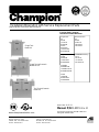
For machines beginning with S/N R3448 and
ending with RE13077060
www.championindustries.com
Beginning with Serial No. R3448 and above
Single Tank
Model 44
Single Tank w/Prewash
Model 66 PW
Two Tank w/Prewash
Model 64
Printed in USA
E-series Rack Conveyor
Dishwasher Model Machines
Dual Tank Rack
64
86 PW
90 PPPW
100 HDPW
120 HDPW
Single Tank
44
66 PW
70 FFPW
80 HDPW
44 WS
66 WSPW
70 WSFFPW
80 WSHDPW
Single Dual-Rinse
44 DR
66 DRPW
70 DRFFPW
80 DRHDPW
44 DRWS
66 DRWSPW
70 DRWSFFPW
80 DRWSHDPW
54 DR
76 DRPW
80 DRFFPW
90 DRHDPW
Chemical Sanitizing
44 LT
66 LTPW
70 LTHDW
80 LTHDPW

COPYRIGHT © 2015 All rights reserved Printed in the USA
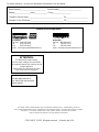
For future reference, record your dishwasher information in the box below.
Model Number__________________________ Serial Number_______________________
Voltage________________Hertz_____________ Phase__________________
Champion Service Agent __________________________________ Tel:______________________
Champion Parts Distributor _________________________________ Tel:______________________
ATTENTION:
The dishwasher model number,
serial number, voltage, hertz and phase
are needed to identify your machine and to
answer questions.
Please have this information on-hand
if you call for service assistance.
National Service Department
In Canada: In the USA:
Toll-free: 800/ 263-5798 Toll-free: 800/ 858-4477
Tel: 905/ 562-4195 Tel: 336/ 661-1556
Fax: 905/ 562-4618 Fax: 336/ 661-1660
For all models:
The data plate mounts to
one side of the top-mounted
control cabinet.
The USGBC and the CaGBC Member Logos are trademarks owned by the U.S. Green Building Council and
The Canadian Green Building Council, respectively, and are used by permission. The logos signify only that Champion
Industries, Inc. is a USGBC member and a CaGBC member; USGBC and CaGBC do not review,
certify nor endorse the products or services offered by its members.

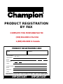
http://www.championindustries.com/canada/register
REGISTER YOUR PRODUCT ONLINE
Make sure you are connected to the internet then enter the address below.
In the U.S.A
In Canada
http://www.championindustries.com/register

PRODUCT REGISTRATION
BY FAX
(336) 661-1660 in the USA
1-(800) 204-0109 in Canada
IMPORTANT IMPORTANT
Model Serial #
Date of Installation:
Company Name:
Telephone #: ( ) ---
Contact:
Address:
Address:
Telephone #:
Contact:
Installation Company:
(Street) Province Postal Code
FAILURE TO REGISTER YOUR PRODUCT MAY VOID YOUR WARRANTY
PRODUCT REGISTRATION CARD
COMPLETE THIS FORM AND FAX TO:

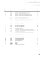
i
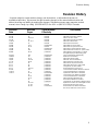
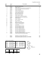
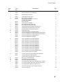
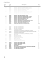
Revision History
Revision History
A revision might be a part number change, new instructions, or information that was not
available at print time. We reserve the right to make changes to this manual without notice and
without incurring any liability by making the changes. Dishwasher owners may request a revised
manual, at no charge, by calling (800.858.4477) in the USA or (800.263.5798) in Canada.
Revision Revised Serial Number Description
Date Pages Effectivity
9.01.04 All RE3448 Released First Edition
9.01.04 20 RE3448 P/N 328473 replaced by 328977
9.01.04 20,23,25 RE3448 Added new door catches
9.01.04 23 RE3448 P/N 327891 replaced with 328974
12.16.04 43, 75,77 RE3448 Added 575 Volt Elements
2/16/05 91 RE3448 Added revised schematics
3/13/08 21,22 RE08024965 Added baffle to prevent drafts
9/27/06 32-35 RE4320 Added rack rear guide to the track
7/17/08 80 RE08065126 Added timer to eliminate blower chatter
3/14/08 N/A RE0705549 Added Solid State Controls for special orders
8/18/09 98-99 J08102541 Added Digital Controls displays to cabinet
and digital display troubleshooting guide
6/12//09 N/A RE09045446 First Rack Model with digital display
10/13/09 All J08102541 Released Second Edition
1/22/10 92-97 J08102541 Added 575V/3PH Part Nos.
1/22/10 110-113 J08102541 Added 24" and 30" Sideloaders
3.17.10 80-83 J08102541 Added Fill Piping and CWT Piping
8.2.10 23 J08102541 Added 120 to set-point instructions
8.2.10 84 J08102541 Added Drain Basket Assy. P/N 107342
8.2.10 89 J08102541 Changed Item 2 P/N to 113984
8.2.10 106-107 J08102541 Revised Illustration and Parts List
8.26.10 107 J08102541 Corrected Item 36 P/N for 0507315 to 601707
11.16.10 55 J08102541 Corrected Item Numbers in Illustration
10.15.12 34-35 RE10095983 Updated 575V Drive Mtr. to 240V/60/1
39 J08102541 Chaned Item 2 from 328045 to 328046
52-53 J08102541 Corrected Item Numbers in Illustration
54-55 J08102541 Added E-84 Wash Manifold P/N's
91 J08102541 Removed Kit 900184 from List NLA
95 J08102541 Chenged Item 1 P/N 114505 for Digital Cabinet
121-150 -------------- Replaced All schems w/Current Digital revisions
27-120 RE3448 Revised Replacement Parts pages
99-101 Re13077060 Revised Item 3 P/N 115019 and added
Item 31 P/N 115018 to Control Cabinet

ii
LIMITED WARRANTY
Champion Industries Inc. (herein referred to as Champion), 3765 Champion Blvd., Winston-Salem, North Carolina 27105,
and P.O. Box 301, 2674 N. Service Road, Jordan Station, Canada, L0R 1S0, warrants machines, and parts,
as set out below.
Warranty of Machines: Champion warrants all new machines of its manufacture bearing the name
"Champion" and installed within the United States and Canada to be free from defects in material and workman
ship for a period of one (1) year after the date of installation or fteen (15) months after the date of shipment by
Champion, whichever occurs rst. [See below for special provisions relating to glasswashers.] The warranty
registration card must be returned to Champion within ten (10) days after installation. If warranty card is not
returned to Champion within such period, the warranty will expire after one year from the date of shipment.
Champion will not assume any responsibility for extra costs for installation in any area where there are
jurisdictional problems with local trades or unions.
If a defect in workmanship or material is found to exist within the warranty period, Champion, at its election,
will either repair or replace the defective machine or accept return of the machine for full credit; provided;
however, as to glasswashers, Champion's obligation with respect to labor associated with any repairs shall end
(a) 120 days after shipment, or (b) 90 days after installation, whichever occurs rst. In the event that Champion
elects to repair, the labor and work to be performed in connection with the warranty shall be done during regular
working hours by a Champion authorized service technician. Defective parts become the property of Champion.
Use of replacement parts not authorized by Champion will relieve Champion of all further liability in connection
with its warranty. In no event will Champion's warranty obligation exceed Champion's charge for the machine.
The following are not covered by Champion's warranty:
a. Lighting of gas pilots or burners.
b. Cleaning of gas lines.
c. Replacement of fuses or resetting of overload breakers.
d. Adjustment of thermostats.
e. Adjustment of clutches.
f. Opening or closing of utility supply valves or switching of electrical supply current.
g. Cleaning of valves, strainers, screens, nozzles, or spray pipes.
h. Performance of regular maintenance and cleaning as outlined in operator’s guide.
i. Damages resulting from water conditions, accidents, alterations, improper use, abuse,
tampering, improper installation, or failure to follow maintenance and operation procedures.
j. Wear on Pulper cutter blocks, pulse vanes, and auger brush.
Examples of the defects not covered by warranty include, but are not limited to: (1) Damage to the exterior or
interior nish as a result of the above, (2) Use with utility service other than that designated on the rating plate,
(3) Improper connection to utility service, (4) Inadequate or excessive water pressure, (5) Corrosion from
chemicals dispensed in excess of recommended concentrations, (6) Failure of electrical components due to
connection of chemical dispensing equipment installed by others, (7) Leaks or damage resulting from such
leaks caused by the installer, including those at machine table connections or by connection of chemical
dispensing equipment installed by others, (8) Failure to comply with local building codes, (9) Damage
caused by labor dispute.
Warranty of Parts: Champion warrants all new machine parts produced or authorized by Champion to be free
from defects in material and workmanship for a period of 90 days from date of invoice. If any defect in
material and workmanship is found to exist within the warranty period Champion will replace the defective
part without charge.
DISCLAIMER OF WARRANTIES AND LIMITATIONS OF LIABILITY. CHAMPION'S WARRANTY IS ONLY TO THE EX-
TENT REFLECTED ABOVE. CHAMPION MAKES NO OTHER WARRANTIES, EXPRESS OR IMPLIED, INCLUDING,
BUT NOT LIMITED, TO ANY WARRANTY OF MERCHANTABILITY, OR FITNESS OF PURPOSE. CHAMPION SHALL
NOT BE LIABLE FOR INCIDENTAL OR CONSEQUENTIAL DAMAGES. THE REMEDIES SET OUT ABOVE ARE
THE EXCLUSIVE REMEDIES FOR ANY DEFECTS FOUND TO EXIST IN CHAMPION DISHWASHING MACHINES AND
CHAMPION PARTS, AND ALL OTHER REMEDIES ARE EXCLUDED, INCLUDING ANY LIABILITY FOR INCIDENTALS
OR CONSEQUENTIAL DAMAGES.
Champion does not authorize any other person, including persons who deal in Champion dishwashing machines
to change this warranty or create any other obligation in connection with Champion Dishwashing Machines.
Limited Warranty

iii
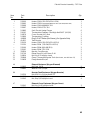
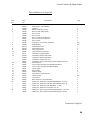
E-series Rack Conveyor Dishwashers
Revisions to this manual......................................................................................................................... i
Limited Warranty ................................................................................................................................... ii
Model Descriptions ................................................................................................................................. iv
Installation ................................................................................................1
Model Details ............................................................................................................1
Receiving ..................................................................................................................2
Plumbing Connections ..............................................................................................2
Drain Connections .....................................................................................................4
Ventilation ..................................................................................................................4
Electrical Connections ...............................................................................................5
Curtain Locations ......................................................................................................8
Hot Water Coil Tank Heat ..........................................................................................9
Door Safety Switches ................................................................................................11
Spray Arm and Scrap Screens ..................................................................................11
Operation .................................................................................................17
Operation .................................................................................................................17
Cleaning and Maintenance ......................................................................................18
Digital Display ..........................................................................................................20
Troubleshooting ........................................................................................................26
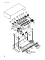
Service Replacement Parts ....................................................................27
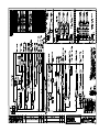
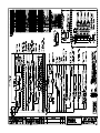
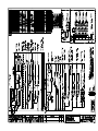
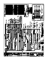
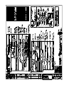
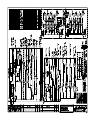
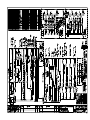
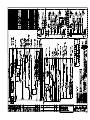
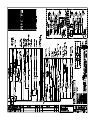
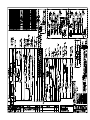
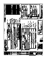
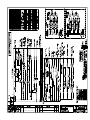
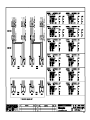
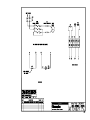
Electrical Schematics..............................................................................121
Table of Contents

iv
Model Descriptions
Electric high temperature single tank and multiple tank rack conveyor dishwashers
with built-in electric boosters in 40°F/22°C rise or optional 70°F/39°C rise.
Steam high temperature single tank and multiple tank rack conveyor dishwasher with
built-in steam booster in 40°F/22°C rise or an optional 70°F/39°C rise booster.
Hot water coil dishwashers utilizing recirculating hot water through a wash tank heater
coil to heat the wash water.
Electric low temperature chemical sanitizing single tank and multiple tank rack conveyor
dishwasher.
Dual Rinse machines utilizing an auxiliary rinse to save energy and improve washability.
The installation, and initial start-up of your dishwasher must be performed by qualied
electricians, plumbers, and authorized service technicians trained in commercial
dishwashers.
Defects and repairs caused by unauthorized installers will not be covered by the
dishwasher warranty.
Model Descriptions

1
Model Details
Champion single tank and two tank rack conveyor dishwashers are fully automatic.
Standard equipment includes 1HP prewash, 2HP wash and 2HP power rinse pumps. The
conveyor drive is a 1/6 HP motor. All models are available in
right-to-left (R-L) or left-to-right (L-R) direction.
Model Numbers
Single Tank - Basic .................................................. 44, 54, 44 WS, 44 LT
Single Tank with 22" Prewash ................................. 66 PW, 76 PW, 66 WS, 66 LT PW
Single Tank with 36" Prewash ................................. 80 HDPW, 90 HDPW, 80WS HDPW
Single Tank with 26" Front Feed Prewash .............. 70 FFPW,80 FFPW, 70 WS FFPW
• The 44 DR and 54 DR basic models are high temperature 180°F/80°C hot final rinse
water sanitizing dishwashers. Prewash options are available in 22", 36", and
26" front feed. Built-in stainless steel electric booster heaters in 40°F/22°C and
70°F/39°C rise are available and steam booster heaters in 40°F/22°C and 70°F/39°C
rise. Dual-Rinse (DR) models feature a recirculating rinse that conserves energy.
• The 44 WS and 44 DRWS models are WaterSaver high temperature 180°F/80°C
hot final rinse water sanitizing dishwashers. Prewash options are available in 22",
36", and 26" front feed. Built-in stainless steel electric booster heaters in 40°F/22°C
and 70°F/39°C rise are available and steam booster heaters in 40°F/22°C and 70°F/39°C
rise. Dual-Rinse (DR) models feature a recirculating rinse that conserves energy.
• The 44 LT and 66 LT models are low temperature 140°F/60°C sodium hypochlorite
(chlorine bleach) sanitizing final rinse to maintain a minimum concentration of
50 PPM on the wares. The concentration of sanitizer must be tested at regular
intervals using chlorine test papers.
Two Tank - Basic .......................................................64, 72, 84
Two Tank with 22" Prewash .......................................86 PW, 94 PW, 106 PW
Two Tank with 36" Prewash .......................................100 HDPW, 108 HDPW, 120 HDPW
Two Tank with 26" Front Feed Prewash ....................90 FFPW, 98 FFPW, 110 FFPW
• The 64, and 84 basic models are high temperature 180°F/80°C hot water final rinse
sanitizing models. Prewash options are available in 22", 36", and 26" front feed.
Built-in stainless steel electric booster heaters in 40°F/22°C and 70°F/39°C rise are
available and steam booster heaters in 40°F/22°C and 70°F/39°C rise.
• All rack conveyor dishwasher models are covered by a 1-year parts and labor limited
warranty.
Model Details

2
Installation
! ATTENTION !
Use caution when moving or lifting the dishwasher to prevent damaging
the dishwasher or the installation site. Check doorway and passageway
clearance before moving the dishwasher. Remove dishwasher front panels
and check under the machine base for obstructions before moving.
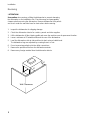
1. Inspect the dishwasher for shipping damage
2. Check the dishwasher interior for curtains, panels and other supplies.
3. Lift the dishwasher off the shipping pallet and move the machine near its permanent location.
4. Leave a minimum of 6" between walls and the rear of the dishwasher.
5. Level the dishwasher side-to-side and front-to-back using a bubble level.
The dishwasher legs are adjusted by screwing them in or out.
6. Do not remove tags attached to the utility connections.
7. Remove the protective film from the dishwasher exterior.
8. Remove any foreign material from the dishwasher interior.
Receiving
Wall Clearances
6"
6"

3
NOTE:
Only qualified personnel should make dishwasher plumbing connections.
Connections must meet local plumbing and sanitary codes.
Improper installation is not covered be the dishwasher warranty.
Hot Water Requirements:
1. Connect a 3/4" NPT hot water supply line to the line strainer located at the top rear of the
dishwasher.
2. For a dishwasher without a booster heater, the hot water connection must supply a
minimum of 180°F/82°C measured at the dishwasher.
3. For a 40°F/22°C rise booster heater, the hot water connection must supply a minimum of
140°F/60°C measured at the dishwasher.
4. For a 70°F/39°C rise booster heater, the hot water connection must supply a minimum of
110°F/43°C measured at the dishwasher.
5. For a single wash tank hot water coil heated dishwasher, the hot water connection must
supply a minimum of 185°F/85°C measured at the dishwasher.
6. For a two-tank hot water coil heated dishwasher, the hot water connection must supply a
minimum of 195°F/91°C measured at the dishwasher.
7. For a low temperature chemical sanitizing dishwasher the hot water connection must
supply a minimum of 140°F/60°C measured at the dishwasher.
8. Install a pressure regulating valve (PRV) before the dishwasher supply connection to
maintain a flowing pressure of 20-25 PSI/137.8-172.4 kPa.
9. Install a service shut-off valve in the supply line, as close to the dishwasher as possible.
The size of the valve must be the same size or larger as the supply line.
Installation
Hot Water Connections
Utilities
Cold Water Requirements:
1. Connect a 1/2" NPT cold water supply line for a dishwasher equipped with a prewash cold
water tempering option. Connection is located at the top of rear of the dishwasher load end.
2. Connect a 1/2" NPT cold water supply line for dishwashers required to have a drain water
temperature tempering option. Request a P/N 452891 for a drain tempering water kit.
Cold Water Connections

4
Installation
Drain Connections
1. The 1-1/2" drain line was removed and packed inside the dishwasher prior to shipping. Install the drain
line once the dishwasher has been placed in its final location.
2. Dual rinse (DR) models have a PVC drain line assembly packed inside the dishwasher also. Remove
this assembly and install it at the unload end of the dishwasher. The drain connection is made to the
main drain line with a hose-type connector.
3. Connect the 1-1/2" NPT drain line to above a drain sink or to a 1-1/2" or larger drain line connection.
4. Observe all local plumbing and sanitary codes when installing.
Steam Supply and Condensate Connections
1. The size of the steam supply line must be a 2" NPT line.
2. Check the steam pressure requirements prior to connecting the steam supply lines. Standard high
steam supply required is 15-30 PSI/103-201 kPa.
3. Low steam supply pressure is 7-14 PSI/48.2-96.5 kPa
4. Connect a steam supply line the same size or larger to the dishwasher at the steam supply strainer
located at the unload end of the dishwasher.
5. Condensate lines must be gravity drain with no back pressure. A condensate lift pump must be
installed if the condensate flow is above the finished floor.
1. DO NOT VENT THE DISHWASHER INTO WALLS, CEILINGS OR ENCLOSED PLACES.
2. Vent stacks with adjustable dampers are supplied with the dishwasher to connect house vent.
3. Connect stainless steel water-tight duct inside the 4" x 16"/ 106mm x 407mm vent stacks supplied
with the dishwasher.
4. A minimum of 6 air changes per hour of kitchen is recommended
Ventilation Guidelines:
Dishwasher without a prewash tank option:
Load end- 200 CFM @ 1/4" SP/ 95 Liters/second
Unload end- 400 CFM @ 1/4" SP/ 189 Liters/second
Dishwasher with a Prewash tank option:
Load end- 150 CFM @ 1/4" SP/ 95 Liters/second
Unload end- 400 CFM @ 1/4" SP/ 189 Liters/second
Dishwashers with more than two tanks:
Load end- 200 CFM @ 1/4" SP/ 95 Liters/second
Unload end- 400 CFM @ 1/4" SP/ 189 Liters/second
Ventilation Connections

5
MACHINE ELECTRICAL CONNECTION
! ATTENTION !
Electrical and grounding connections
must comply with the National Electrical Code
or in the absence of a National Code then
all Local Electrical Codes.
A qualified electrician MUST compare the
electrical power supply with the machine
electrical specifications stamped on the
MACHINE ELECTRICAL
CONNECTION PLATE
located inside the control cabinet before
connecting the main power to the dishwasher.
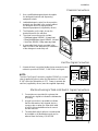
1. The Main incoming power to the dishwasher is made at the top of machine
in the control cabinet.
2. The electrician must connect the incoming power based on the information
that is stamped on the Machine Electrical Connection Plate.
3. Any change to the Machine Electrical Connection Plate must be approved
by the factory in advance.
4. The dishwasher main power terminal block is located inside the top-mounted
control cabinet.
5. A knock-out plug is provided at the rear of the control cabinet for electrical
service connections.
6. Built-in electric booster heaters have a separate main power connection
except Models 44 WS and 66WS.
7. Electric blower-dryers have a separate main power connection.
8. If the machine incoming voltage exceeds 208-240VAC then the Dual Rinse
(DR) models have a step-down transformer mounted on the frame of the
dishwasher to reduce the incoming voltage for the DR drain pump.
! ATTENTION !
A qualified electrician must connect the main incoming power to the
dishwasher in accordance with all local codes and regulations or in the
absence of local codes in accordance with the National Electrical Code.
WARNING:
Electrocution or serious injury may result
when working on an energized circuit.
Disconnect power at the main breaker or service
disconnect switch before working on the circuit.
Lock-out and tag the breaker to indicate that
work is being performed on the circuit.
Installation
Electrical Connections

6
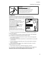
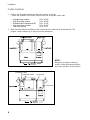
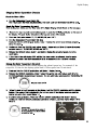
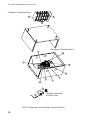
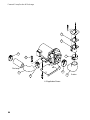
1. Motor rotation was set at the factory.
2. The conveyor drive motor rotation is indicated by a red
arrow located on the side of the motor.
3. Check if all motors are running in the wrong direction.
4. Reverse the L1 and L2 wires on the output side of the dishwasher Main
Terminal Block (MTB) located inside the top-mounted control cabinet.
5. The photograph to the right shows the conveyor drive motor with its direction arrow.
6. A wash pump/motor assembly can be seen in the back.
Installation
Electrical Connections (continued)
Motor Rotation
THREE PHASE
POWER CONNECTION
LINE IN
L1 L2 L3
GRD
Main Terminal Block Inside the Top-
mounted Control Cabinet.
Motor Direction Rotation Label on Motor Frame.
WARNING:
Moving Conveyor Parts may cause INJURY OR DEATH.
Keep hands and clothing clear of the conveyor when the
conveyor is moving.
USE EXTREME CAUTION WHEN THE CONVEYOR
IS MOVING.

7
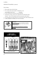
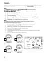
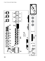
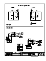
1. Use a qualified detergent/chemical supplier
for detergent/chemical and dispensing
equipment needs.
2. Labeled detergent control circuit connection
terminals are provided in the control cabinet
for detergent and rinse agent/sanitizer
dispensing equipment (supplied by others).
3. The illustration on the right, shows the
terminal board for the machine.
4. The signal connection points include:
• Detergent signal 120VAC, 1A max load.
• Rinse aid/Sanitizer signal 120VAC, 1A load.
• Vent Fan 120VAC, 1Amp max amp load
5. A removable black plug is provided in the
load end side of the wash tank for installation
of the detergent conductivity cell.
SIGNAL ONLY
VENT FAN
COMMON
COMMON
120V
DETERGENT
120V
RINSE AID
120V
Installation
Chemical Connections
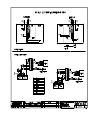
MACHINE
RUNNING
TABLE
LIMIT
SWITCH
SIGNAL ONLY
1. Connections are provided for systems that
require that a signal to indicate the dishwasher
is running.
2. A signal connection is provided to indicate
that the dishwasher has stopped due to a
conveyor jam or when the clean dish table
is full of racks and additional racks cannot
exit the machine.
3. The table limit switch option is recommended
be installed on all dishwashers and can be
ordered from the factory P/N 407400.
Machine Running & Table Limit Switch Signal Connections
1. A terminal block is provided inside the top-mounted control
cabinet to provide a 120VAC, 1 AMP Max Load signal.
NOTE:
The Vent Fan Signal Connection supplies 120VAC to a control
relay (supplied by others) when the dishwasher is ON and
O VAC when the dishwasher is OFF. Power to operate the
vent fan (supplied by others) must be supplied separately.
Vent Fan Signal Connection
SIGNAL ONLY
VENT FAN
COMMON
COMMON
120V
DETERGENT
120V
RINSE AID
120V
Detergent
Probe Location

8
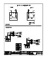
Installation
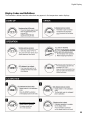
Curtain Locations
1. Refer to the illustrations below and hang the curtains as shown.
J-hooks are located in the corners of each section to accept the curtain rods.
• Standard long curtains 24” x 20-1/4”
• High hood long curtains 24” x 22-3/4”
• Standard short curtains and DR 24” x 13-1/4”
• High hood short curtains 24” x 20-1/4”
• Final rinse curtain 24” x 6-1/4”
2. Make sure the that the short flaps of the curtains face the load end of the dishwasher. The
longest curtains always go on each end of the dishwasher.
Single Tank Dishwasher Curtain Locations.
DRFR Long Curtain
Long CurtainDual RInse Curtain
Final Rinse Curtain
Dual Rinse Single Tank Dishwasher with Prewash Curtains.
NOTE:
Misplacing a curtain or failing to
install a curtain will adversely affect
the proper operation of the machine.

9
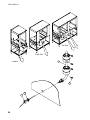
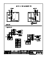
Installation
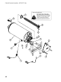
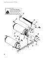
Hot Water Coil Tank Heat
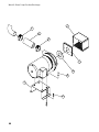
Purging Air from the Dishwasher/Booster Heater System
CAUTION:
PERMANENT DAMAGE to the hot water recirculating pump can
occur if the air is not purged from the dishwasher/booster heater
system prior to placing the dishwasher into service.
Follow the instructions carefully to prevent damage
to the dishwasher hot water recirculating pump.
The air trapped in the Dishwasher Hot Water Recirculating Pump and Water Lines must be purged.
Refer to the illustration below and follow the procedure on the next page.
The dishwasher recirculating pump is located
near the base at the booster end of the machine.
The air purge petcock is located behind the dishwasher
lower front panel at the booster end of the machine.
A
B

10
Refer to the illustration on the previous page and follow the procedure below to purge the air from the
system. Plumbing and electrical service connections must be completed before purging the system.
To purge the air:
1. Make sure the dishwasher main power switch is OFF.
2. Make sure the main water supply valve located at the booster heater is OFF.
3. Open petcock (A) on the inlet side of the dishwasher hot water heater coil.
4. Remove the silver plug located in the center of the recirculating pump.
5. Turn the main water supply valve ON. Water will begin to ll the booster heater and the dishwasher
heater coil.
6. Water and air will begin to ow out of the purge petcock and the recirculating pump and eventually
only water will be observed.
7. Turn the booster heater power switch ON.
8. Turn the dishwasher power switch ON. The dishwasher wash tank will begin to ll with water.
9. Continue to observe the petcock and the recirculating pump and make sure that there is a steady
stream of water is owing from (A) and (B).
10. Replace the silver plug (B) in the center of the recirculating pump then close the petcock (A).
11. Turn the dishwasher power switch OFF.
12. Purging is complete.
Purging Air from the Dishwasher/Booster Heater System (continued)
Installation
Hot Water Coil Tank Heat

11
Dishwasher access doors are equipped with a door safety switch that automatically
stops the dishwasher pumps and conveyor drive if a door is raised while the dishwasher
is running. In addition, the dishwasher will not start if a door is left open.
1. If the dishwasher is running and a door is raised, then lighted GREEN START
pushbutton goes out and the pumps and conveyor drive stop.
2. Check the interior of the dishwasher for any dish racks still in the machine.
These dish racks must be washed again to ensure they are washed and sanitized
completely.
3. To restart the dishwasher, make sure all doors are closed, then push the GREEN
START pushbutton.
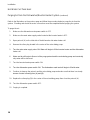
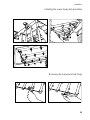
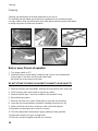
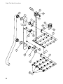
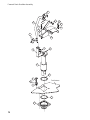
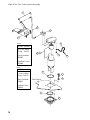
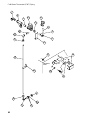
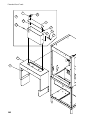
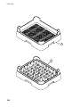
The illustrations below and on the proceeding pages illustrate how to install and
remove the spray arm assemblies and scrap screens.
Spray Arm and Scrap Screen Installation
Removing the lower spray arm assembly
Installation
Door Safety Switches

12
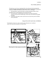
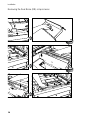
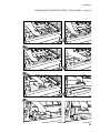
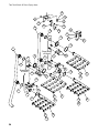
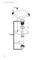
Installation
Removing the Spray Arm End Plugs
Installing the Lower Spray Arm Assembly
Page is loading ...
Page is loading ...
Page is loading ...
Page is loading ...
Page is loading ...
Page is loading ...
Page is loading ...
Page is loading ...
Page is loading ...
Page is loading ...
Page is loading ...
Page is loading ...
Page is loading ...
Page is loading ...
Page is loading ...
Page is loading ...
Page is loading ...
Page is loading ...
Page is loading ...
Page is loading ...
Page is loading ...
Page is loading ...
Page is loading ...
Page is loading ...
Page is loading ...
Page is loading ...
Page is loading ...
Page is loading ...
Page is loading ...
Page is loading ...
Page is loading ...
Page is loading ...
Page is loading ...
Page is loading ...
Page is loading ...
Page is loading ...
Page is loading ...
Page is loading ...
Page is loading ...
Page is loading ...
Page is loading ...
Page is loading ...
Page is loading ...
Page is loading ...
Page is loading ...
Page is loading ...
Page is loading ...
Page is loading ...
Page is loading ...
Page is loading ...
Page is loading ...
Page is loading ...
Page is loading ...
Page is loading ...
Page is loading ...
Page is loading ...
Page is loading ...
Page is loading ...
Page is loading ...
Page is loading ...
Page is loading ...
Page is loading ...
Page is loading ...
Page is loading ...
Page is loading ...
Page is loading ...
Page is loading ...
Page is loading ...
Page is loading ...
Page is loading ...
Page is loading ...
Page is loading ...
Page is loading ...
Page is loading ...
Page is loading ...
Page is loading ...
Page is loading ...
Page is loading ...
Page is loading ...
Page is loading ...
Page is loading ...
Page is loading ...
Page is loading ...
Page is loading ...
Page is loading ...
Page is loading ...
Page is loading ...
Page is loading ...
Page is loading ...
Page is loading ...
Page is loading ...
Page is loading ...
Page is loading ...
Page is loading ...
Page is loading ...
Page is loading ...
Page is loading ...
Page is loading ...
Page is loading ...
Page is loading ...
Page is loading ...
Page is loading ...
Page is loading ...
Page is loading ...
Page is loading ...
Page is loading ...
Page is loading ...
Page is loading ...
Page is loading ...
Page is loading ...
Page is loading ...
Page is loading ...
Page is loading ...
Page is loading ...
Page is loading ...
Page is loading ...
Page is loading ...
Page is loading ...
Page is loading ...
Page is loading ...
Page is loading ...
Page is loading ...
Page is loading ...
Page is loading ...
Page is loading ...
Page is loading ...
Page is loading ...
Page is loading ...
Page is loading ...
Page is loading ...
Page is loading ...
Page is loading ...
Page is loading ...
Page is loading ...
Page is loading ...
Page is loading ...
Page is loading ...
Page is loading ...
Page is loading ...
-
 1
1
-
 2
2
-
 3
3
-
 4
4
-
 5
5
-
 6
6
-
 7
7
-
 8
8
-
 9
9
-
 10
10
-
 11
11
-
 12
12
-
 13
13
-
 14
14
-
 15
15
-
 16
16
-
 17
17
-
 18
18
-
 19
19
-
 20
20
-
 21
21
-
 22
22
-
 23
23
-
 24
24
-
 25
25
-
 26
26
-
 27
27
-
 28
28
-
 29
29
-
 30
30
-
 31
31
-
 32
32
-
 33
33
-
 34
34
-
 35
35
-
 36
36
-
 37
37
-
 38
38
-
 39
39
-
 40
40
-
 41
41
-
 42
42
-
 43
43
-
 44
44
-
 45
45
-
 46
46
-
 47
47
-
 48
48
-
 49
49
-
 50
50
-
 51
51
-
 52
52
-
 53
53
-
 54
54
-
 55
55
-
 56
56
-
 57
57
-
 58
58
-
 59
59
-
 60
60
-
 61
61
-
 62
62
-
 63
63
-
 64
64
-
 65
65
-
 66
66
-
 67
67
-
 68
68
-
 69
69
-
 70
70
-
 71
71
-
 72
72
-
 73
73
-
 74
74
-
 75
75
-
 76
76
-
 77
77
-
 78
78
-
 79
79
-
 80
80
-
 81
81
-
 82
82
-
 83
83
-
 84
84
-
 85
85
-
 86
86
-
 87
87
-
 88
88
-
 89
89
-
 90
90
-
 91
91
-
 92
92
-
 93
93
-
 94
94
-
 95
95
-
 96
96
-
 97
97
-
 98
98
-
 99
99
-
 100
100
-
 101
101
-
 102
102
-
 103
103
-
 104
104
-
 105
105
-
 106
106
-
 107
107
-
 108
108
-
 109
109
-
 110
110
-
 111
111
-
 112
112
-
 113
113
-
 114
114
-
 115
115
-
 116
116
-
 117
117
-
 118
118
-
 119
119
-
 120
120
-
 121
121
-
 122
122
-
 123
123
-
 124
124
-
 125
125
-
 126
126
-
 127
127
-
 128
128
-
 129
129
-
 130
130
-
 131
131
-
 132
132
-
 133
133
-
 134
134
-
 135
135
-
 136
136
-
 137
137
-
 138
138
-
 139
139
-
 140
140
-
 141
141
-
 142
142
-
 143
143
-
 144
144
-
 145
145
-
 146
146
-
 147
147
-
 148
148
-
 149
149
-
 150
150
-
 151
151
-
 152
152
-
 153
153
-
 154
154
-
 155
155
-
 156
156
-
 157
157
-
 158
158
-
 159
159


Moyer Diebel 100HDPW Owner's manual
- Category
- Dishwashers
- Type
- Owner's manual
Ask a question and I''ll find the answer in the document
Finding information in a document is now easier with AI
Related papers
-
Moyer Diebel MD-44 User manual
-
-
Champian UH-200B Owner's manual
-
-
Champion Industries D-HBTCM5 Owner's manual
-
Moyer Diebel PR36/60KB/R1247 Owner's manual
-
Moyer Diebel D-H1TM5 User manual
-
-
Moyer Diebel FFPR26/44KB,FFPR26/54KB Owner's manual
Other documents
-
Champion 70 FFPW User manual
-
Champion 70 FFPW Specification
-
Champion 94 FFPW User manual
-
-
-
-
GE DH2000 User manual
-
-
Champion D-H1M5 User manual
-
Champion UH-200B Operating instructions