

While every precaution has been taken to ensure accuracy and completeness in this
manual, EGS Electrical Group, LLC. assumes no responsibility, and disclaims all liability for
damages resulting from use of this information or for any errors or omissions.
©2009 EGS Electrical Group, LLC. All rights reserved. Specications are subject to change
without notice.
®SolaHD name and logo are registered trademarks of EGS Electrical Group, LLC. All
names referred to are trademarks or registered trademarks of their respective owners.
S3K Series Instruction Manual • iiVisit our Web site at www.solahd.com

S3K Series Instruction Manual • iiiVisit our Web site at www.solahd.com
Table of Contents
1.0 Important Safety Instructions ...................................................................... 4
2.0 Product Description ................................................................................ 5–6
3.0 Pre-Installation ............................................................................................ 7
4.0 Installation ............................................................................................... 7–8
5.0 Operation .............................................................................................. 9–10
6.0 Alarms ....................................................................................................... 10
7.0 Software & Interface ........................................................................... 11–12
8.0 Maintenance & Storage ............................................................................ 12
9.0 Troubleshooting ........................................................................................ 13
10.0 Specications ....................................................................................... 14–15
11.0 Registration & Warranty ............................................................................ 15

S3K Series Instruction Manual • 4Visit our Web site at www.solahd.com
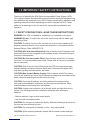
1.0 Important Safety InStructIonS
Thank you for selecting the S3K Series Uninterruptible Power System (UPS).
This manual contains important safety instructions that should be followed during
the installation and operation of your UPS. Please read all safety, installation and
operating instructions before attempting to install or operate the UPS. Please
adhere to all warnings on the unit and in this manual during installation and
operation.
1.1 SAFETY PRECAUTIONS—SAVE THESE INSTRUCTIONS
WARNING: The UPS is intended for installation in a controlled environment.
WARNING (Fuses): To reduce the risk of re, replace only with the same type
and rating of fuse.
CAUTION: To reduce the risk of re, connect only to a circuit provided with 20
amperes maximum branch circuit overcurrent protection in accordance with the
National Electric Code, ANSI/NFPA 70.
CAUTION (UPS with Internal Batteries): Risk of electric shock! Hazardous live
parts inside this unit are energized from the battery supply, even when the input
ac power is disconnected.
CAUTION (No User-serviceable Parts): Risk of electric shock! Do not remove
the cover—no user-seviceable parts inside. Please refer all repairs to a qualied
service technician.
CAUTION: Risk of electric shock! Disconnect the UPS from the mains supply
before installing a computer interface signal cable. Reconnect the power cord
only after signaling interconnections are made.
CAUTION (Non-isolated Battery Supply): Risk of electric shock! The battery
circuit is not isolated from the ac input. Hazardous voltage may exist between the
battery terminals and the ground; test before touching.
CAUTION: Servicing of batteries should be performed or supervised by
personnel knowledgeable in batteries and the required precautions. Keep
unauthorized personnel away from the batteries.
CAUTION: A battery can present a risk of electric shock and high-short circuit
current. The following precautions should be observed when working on
batteries:
• Remove watches, rings or other metal objects.
• Use tools with insulated handles.
CAUTION: Do not open or mutilate the battery. Released electrolyte is harmful to
the skin and eyes and may be toxic.
CAUTION: Do not dispose of batteries in a re—they may explode.
CAUTION: When replacing batteries, replace with the same number and type.

S3K Series Instruction Manual • 5Visit our Web site at www.solahd.com
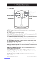
2.0 Product Description
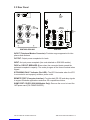
2.1 Front Panel
BATTERY CHARGE
LOAD POWER
OVERLOAD
ON BATTERY
VOLTAGE REDUCTION
ON-LINE
ON/TEST
OFF
REPLACE BATTERY
VOLTAGE BOOST
ON/TEST Button: Turns on the UPS to power the loads. It also activates the
UPS self-test.
OFF Button: Turns off the UPS and the loads.
REPLACE BATTERY Indicator (Red LED): The LED illuminates when the UPS
battery is no longer useful and must be replaced.
VOLTAGE BOOST Indicator (Yellow LED): The LED illuminates when the UPS
is correcting a low utility voltage condition. The loads will continue to receive
normal power.
BATTERY CHARGE Bar Graph: The display shows the present battery charge
as a percentage of the battery capacity.
LOAD POWER Bar Graph: The display shows the power being drawn by the loads.
OVERLOAD Indicator (Red LED): The LED illuminates when the loads connected
to the UPS exceed capacity.
ON BATTERY Indicator (Green LED): The LED illuminates when the UPS is
supplying battery power to the loads.
VOLTAGE REDUCTION Indicator (Yellow LED): The LED illuminates when
the UPS is correcting a high utility voltage condition. The loads will continue to
receive normal power.
ON-LINE Indicator (Green LED): The LED illuminates when the line input
voltage is normal.

S3K Series Instruction Manual • 6Visit our Web site at www.solahd.com
2.2 Rear Panel
M3
SCREWS
(2X)
OUTPUT
INPUT
USB REMOTE
SNMP PORT COVER
S3K700 & S3K1000 S3K1600
IN OUT
OUTPUT
INPUT FUSE
REMOTE
PORT
SITE
WIRING
FAULT
SITE
WIRING
FAULT
IN OUT
CIRCUIT
BREAKER
IN/OUT (Telephone/Modem Connector): Provides surge suppression for tele-
phones and modems.
OUTPUT: Output power receptacles for loads.
INPUT: Ac input power receptacle (line cord attached on S3K1600 models).
FUSE or CIRCUIT BREAKER: Blows when the connected loads exceed the
protected receptacle’s capacity. The center plungers of the fuse will extend when
tripped.
SITE WIRING FAULT Indicator (Red LED): The LED illuminates when the UPS
is connected to an improperly wired ac power outlet.
REMOTE PORT (Computer Interface): Provides both RS-232 and relay signals
to support Windows applications and other OS compatible solutions.
SNMP PORT COVER (S3K1600 Models Only): Remove the cover to insert the
.NETpower card (P/N: SNMPCARDPC).

S3K Series Instruction Manual • 7Visit our Web site at www.solahd.com
3.0 Pre-Installation
Inspect the UPS upon receipt. Damage that may have occurred in transit is not
covered under the warranty. If shipping damage is present, please contact your
local carrier and SolaHD distributor immediately.
Note: The packaging material is recyclable. Please reuse or dispose of it in a
responsible manner.
4.0 Installation
4.1 Installation Requirements
• Install the UPS in a protected area with adequate ventilation and free from
excessive dust.
• Do not expose the UPS to corrosive air.
• Avoid direct sunlight, rain and high humidity.
• Do not operate the UPS where the temperature and humidity are out of the
specied limits (operating temperature: 0°C to +40°C; humidity: 0% to 95%).
Keep away from re and extremely hot locations.
• Maintain a clearance of 4 inches (100 mm) between the UPS rear panel and
the wall and 1 inch (25.4 mm) between the UPS sides and the wall. Keep the
air inlets unobstructed to facilitate ventilation and heat dissipation.
• Do not stack materials on top of the UPS.
• Never leave the UPS on an uneven surface.
4.2 Installation Instructions
4.2.1 Connect to Utility Power
Connect the UPS line cord to the IEC INPUT receptacle on the rear panel of the
UPS (line cord already attached on S3K1600 models). Connect the other end of
the line cord to the ac input power outlet.
4.2.2 Charge the Battery
The UPS charges its battery whenever it is connected to utility power, even when
the unit is off. For best results, charge the battery for 8 hours before initial use.
4.2.3 Turn On the UPS
Press the ON/TEST button.

S3K Series Instruction Manual • 8Visit our Web site at www.solahd.com
4.2.4 Connect the Loads
Connect the loads to the OUTPUT receptacles on the rear panel of the UPS.
CAUTION: Never connect a laser printer or plotter to the UPS with other
computer equipment. Laser printers and/or plotters will require their own UPS,
as they periodically experience high inrush surge currents, which may cause an
overload.
Note: Be careful not to overload the UPS. An audible alarm will beep continu-
ously and the front panel OVERLOAD LED will illuminate to indicate an overload
status. The UPS will shut down automatically to protect its internal circuitry.
4.2.5 Check the Site Wiring Fault Indicator
After completing the above steps, check the SITE WIRING FAULT indicator on
the rear panel of the UPS. A light will be present if the UPS is plugged into an
improperly wired ac power outlet. Detected wiring faults include ground and hot-
neutral polarity reversal.
4.2.6 Connect the Telephone or Modem (if applicable)
Connect the source line to the IN connector. Connect the equipment to the OUT
connector.
CAUTION: To reduce the risk of re, use only No. 26 AWG or larger telecommu-
nication line cord.
4.2.7 Connect Computer Interface
UPSMON software (or other power management software) and an optional
interface kit can be used with this UPS. If used, connect the interface cable to
the REMOTE PORT on the rear panel of the UPS and to the host computer (either
COM 1 or COM 2).
CAUTION: Use only factory supplied or authorized UPS interface cables!
Note: Computer interface connection is optional. The UPS works properly
without a computer interface connection.
Note: Only use kits supplied or approved by the manufacturer.
4.2.8 Install the Optional .NETpower Card (S3K1600 Models Only)
Remove the SNMP port cover. Insert the .NETpower card (P/N: SNMPCARDPC)
and secure with screws. Use network cables (supplied by user) to connect the
UPS to the computer network port.
Please refer to the .NETpower card CD-ROM for conguration settings and
further instructions.

S3K Series Instruction Manual • 9Visit our Web site at www.solahd.com
5.0 Operation
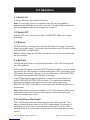
5.1 Switch On
Press the ON button for at least 0.5 seconds.
Note: If normal utility power is not present, the UPS may be engaged by
depressing the ON button for at least 3 seconds. The load will be powered from
the internal batteries until the discharge point is reached.
5.2 Switch Off
Hold the OFF button until the ON-LINE or ON BATTERY LEDs are no longer
illuminated.
5.3 Silence
When the UPS is in backup mode, press the ON button for at least 1 second to
silence the audible alarm. (This function is disabled when the UPS status is either
LOW BATTERY or OVERLOAD.)
Note: In backup mode, the UPS will automatically turn off if the connected loads
are not operating.
5.4 Self-test
Use the self-test function to verify both the operation of the UPS and the condi-
tion of the batteries.
With normal utility power, push the ON/TEST button for at least 1 second. During
the self-test, the UPS operates in backup mode (green LED is illuminated). If the
UPS passes the self-test, it returns to line-interactive mode. (The ON BATTERY
LED goes off and the ON-LINE LED goes on steadily.)
If the UPS has failed to pass the self-test, it returns to line-interactive mode
and the REPLACE BATTERY LED illuminates. (The loads are not affected.)
Recharge the batteries overnight and perform the self-test again. If the
REPLACE BATTERY LED is still on, contact your local SolaHD distributor for a
replacement.
Note: When replacing the internal batteries (12 V/7 Ah), disconnect utility power
before opening the case. Take note of the polarity before installing the new
batteries to avoid a short circuit.
5.5 Load Power Bar Graph
The 5-LED display shows the power drawn from the UPS by the load. The
display indicates the percentage of the UPS’s rated capacity. For example: If
three LEDs are lit, the load is drawing between 50% and 67% of the UPS’s
capacity. If the UPS is overloaded, the overload LED illuminates and the alarm
sounds.

S3K Series Instruction Manual • 10Visit our Web site at www.solahd.com
5.6 Battery Charge Bar Graph
The 5-LED display shows the present charge of the UPS’s batteries as a
percentage of the batteries’ capacity. When all ve LEDs are illuminated, the
batteries are fully charged. When only two LEDs are illuminated, the batteries
can supply less than 2 minutes of run time for the load.
5.7 Cold Start
When the UPS is off and there is no utility power, you can use the cold start
feature to apply power to the loads from the UPS’s batteries. Press the ON/TEST
button until the UPS beeps.
5.8 Shutdown Mode
In shutdown mode, the UPS stops supplying power to the load and waits for
the return of utility power. If there is no utility power present, external devices
(e.g. servers) connected to the computer interface can command the UPS to
shutdown. This is normally done to preserve battery capacity after the graceful
shutdown of protected servers. The UPS will scroll the front panel indicators
sequentially in shutdown mode.
6.0 Alarms
6.1 Backup (slow beeping)
When the UPS is operating in backup mode, the UPS will sound an audible alarm
with a beep every four seconds. The alarm stops when the UPS returns to the
line-interactive mode. The alarm may be silence by pressing the ON/TEST button
while in backup mode. Press the ON/TEST button again to reactivate the sound.
6.2 Low Battery (rapid beeping)
In backup mode when the energy of batteries reaches lower levels (about
20%–30%), the UPS beeps rapidly until it shuts down from battery exhaustion or
returns to line-interactive mode. The low battery alarm cannot be silenced.
6.3 Overload (continuous beeping)
When the UPS output exceeds 100% of nominal for 20 seconds or 125% for 2
seconds, an audible alarm will sound and the front panel OVERLOAD LED will
illuminate. The UPS will shut down automatically to protect its internal circuitry.

S3K Series Instruction Manual • 11Visit our Web site at www.solahd.com
7.0 Software & Interface
7.1 Power Monitoring Software
UPSMON software (or other power monitoring software) utilizes a standard
RS-232 interface to perform monitoring functions and an orderly shutdown of
the protected equipment in the event of power failure. UPSMON displays all the
diagnostic symptoms on the monitor, including voltage, frequency and battery
levels. UPSMON is available for Windows applications and other OS compatible
solutions.
7.2 .NETpower Card (optional—S3K1600 models only)
The .NETpower card (P/N: SNMPCARDPC) provides an advanced, yet easy-
to-use network management function which supports both SNMP and HTTP.
Features include: multiple system shutdown, event notication, scheduling, and
control and conguration of the UPS remotely.
The .NETpower card must be inserted into the SNMP PORT on the rear panel of
the UPS. Please refer to the .NETpower card CD-ROM for further instructions.
7.3 Interface Kits (optional)
Interface kits include a required interface cable to convert status signals from the
UPS into signals which an individual operating system will recognize.
The interface cable must be connected to the REMOTE PORT on the rear panel
of the UPS and to the host computer (either COM 1 or COM 2). Please refer to
the READ.ME le for further instructions.
CAUTION: Use only factory supplied or authorized UPS interface cables!
7.4 Remote Port (computer interface)
The REMOTE PORT on the rear panel of the UPS may be connected to a host
computer to allow for UPS status monitoring and operation control. Functions
include:
• Broadcasting a warning when power fails;
• Closing any open le before the batteries are exhausted;
• Turning off the UPS.
Please refer to 7.4.1 on page 12 for Remote Port PIN Congurations.

S3K Series Instruction Manual • 12Visit our Web site at www.solahd.com
7.4.1 Remote Port PIN Configurations
PIN
Description I/O
2
Power fail. Generates a high to low signal when the line fails.
Notes: Normally open status; closed when active. Open collector output must
be pulled up to a common referenced supply no greater than +40 V dc. The
transistors are capable of a maximum non-inductive dc load of 25 mA. Use
only pin 4 as the common.
Output
4Reference ground for PINs 2 & 5 N/A
5
Battery low. Generates a high to low signal when the internal battery of the
UPS has less than 5 minutes of backup time remaining.
Notes: Normally open status; closed when active. Open collector output must
be pulled up to a common referenced supply no greater than +40 V dc. The
transistors are capable of a maximum non-inductive dc load of 25 mA. Use
only pin 4 as the common.
Output
6
Remote shutdown of the UPS
Notes: PIN 6 has a multi-purpose functionality: (1) Will shut down the UPS
when a high RS-232 level is sustained on PIN 6 for 0.36 seconds; (2) Is the
RS-232 data input (R x D). Keep this pin at high voltage (+5 V to +12 V) for
500 ms to shutdown the UPS. Activates when in the battery mode only.
Input
7Reference ground for PIN 6 N/A
9RS-232 data output Output
Note: PINS 2 and 5 rating: +40 V dc, 25 mA non-inductive
8.0 Maintenance & Storage
8.1 Maintenance
• Keep the unit clean (wipe with a soft, damp cloth) and vacuum the ventilation
intake periodically.
• Check for loose and bad connections monthly.
8.2 Storage Conditions
• Before storing, charge the UPS’s batteries for at least 4 hours.
• Store the UPS covered and upright in a cool, dry location, with the batteries fully
charged.
• To avoid unnecessary draining of the batteries, remove any accessories in the
accessory slot and disconnect any cables connected to the REMOTE PORT.
• During extended storage in environments where the ambient temperature is
-15°C to +30°C (+5°F to +86°F), charge the UPS’s batteries every 6 months;
+30°C to +45°C (+86°F to +113°F), charge the UPS’s batteries every 3 months.

S3K Series Instruction Manual • 13Visit our Web site at www.solahd.com
9.0 Troubleshooting
Problem Probable Cause Solution
UPS won’t operate after
pressing the ON/TEST or OFF
button
No LEDs; no warning sounds
Problem with input power
source Check the input power source
Fuse blown on rear panel Replace fuse with same type
and rating and check load
ON/TEST button was not
pressed for 1+ seconds
Press the ON/TEST button for
more than 2 seconds
Output short circuit or overload
on UPS
Turn off UPS. Remove all loads
to ensure there are no problems
or internal short circuits. Press
the ON/TEST button for more
than 2 seconds.
Indicates no utility with a
warning every few seconds
No power source input Check the input power source
Fuse blown on rear panel Replace fuse with same type
and rating and check load
Fault light is on and the alarm
keeps beeping UPS needs repair Contact your distributor or Tech-
nical Support for assistance
Continuous beeping Overload condition Remove the overload. Refer to
the output specications.
Utility indicator light is on Fuse blown on the rear panel Replace fuse with same type
and rating and check load
UPS has reduced battery time
Batteries are not fully charged Recharge the UPS for at least
4 hours
UPS overload
Check the load power display
and remove any non-essential
loads
Batteries are aged and can’t be
fully charged
Replace the batteries. Contact
your distributor or Technical
Support for assistance.
Battery light ashes when
power of UPS is supplied by
utility
Voltage of batteries is too low Recharge the UPS for at least
4 hours
Batteries are disconnected Check the connections
Damage present on battery
packs
Replace the battery packs
immediately
For further assistance, please contact SolaHD Technical Support at:
U.S.: (800) 377-4384 • International: (847) 268-6651 • E-mail: [email protected]

S3K Series Instruction Manual • 14Visit our Web site at www.solahd.com
10.0 Specifications
Parameter Catalog Number
S3K700 S3K1000 S3K1600
Capacity 700 VA/480 W 1000 VA/750 W 1440 VA/1200 W
INPUT
Nominal Voltage 120 V ±25%, single phase
Frequency 50 or 60 Hz ±5% (auto-sensing)
OUTPUT
Voltage (on battery) Pure sine wave output at nominal ±5%
Frequency (on battery) 50 or 60 Hz ±0.5%
Voltage Regulation
(AVR)
AVR automatically increases output voltage 15% above input voltage if
-9% to -25% of nominal is detected. AVR decreases output voltage 15%
below input voltage if +9% to +25% of nominal is detected.
PROTECTION & FILTERING
Spike Protection 320 J, 2 ms
Unit Input Fuse for overload & short circuit protection
EMI/RFI Filter 10 dB at 0.15 MHz; 50 dB at 30 MHz
Overload Protection UPS automatically shuts down if overload exceeds
100% of nominal at 20 s and 125% at 2 s
Transfer Time 2–4 ms, including detection time
Short Circuit UPS output cuts off immediately or input fuse protection
ENVIRONMENT
Operating Temperature 0°C to +40°C
Humidity 0 to 95%, non-condensing
Maximum Elevation 10,000 ft. (3,000 m)
Audible Noise <40 dBA
(1 m from surface)
<45 dBA
(1 m from surface)
PHYSICAL
Dimensions (W x D x H),
inches [mm]
5.5 x 17.2 x 8.27
[140 x 436 x 210]
6.7 x 17.7 x 8.9
[170 x 450 x 226]
Net Weight, lb. [kg] 31.9 [14.5] 34.8 [15.8] 66.0 [30.0]
Shipping Weight, lb. [kg] 34.1 [15.5] 37.0 [16.8] 70.4 [32.0]
Input Inlet IEC 320 power inlet to 5-15P plug line cord Attached cord to 5-15P
Output Receptacles (4) NEMA 5-15R (6) NEMA 5-15R
BATTERY
Type Hot swappable, sealed, maintenance-free, lead acid
Typical Recharge Time 4 hours (to 90% of full capacity)
Protection Automatic self-test & discharge protection. Replace battery indicator.
Backup Time 10–30 min. (depending on the load)

S3K Series Instruction Manual • 15Visit our Web site at www.solahd.com
Parameter Catalog Number
S3K700 S3K1000 S3K1600
Backup Time at Full
Load 5 min. 3.5 min. 3 min.
Backup Time at Half
Load 14 min. 12.5 min. 10 min.
ALARMS
Battery Backup Slow beeping sound (about 0.25 Hz)
Battery Low Rapid beeping sound (about 1.0 Hz)
Overload Continuous beeping sound
INTERFACE
RS-232 Interface Bidirectional communication port
USB N/A USB port
COMMUNICATION
Option Card N/A .NETpower card
(P/N: SNMPCARDPC)
AGENCY APPROVALS
Safety UL1778, CAN/CSA-C22.2 No. 107, FCC Part 15 Subpart B Class B (1998)
11.0 Registration & Warranty
11.1 Product Registration
To register your product for updates and information on service and support, visit
our Web site at: http://www.solahd.com/support/registration.htm
11.2 Warranty Information
Please see the enclosed “Terms & Conditions of Sale”.

Part Number: A272-076 Rev 3
August 24, 2009
Technical Support
U.S.: (800) 377-4384
International: (847) 268-6651
E-mail: [email protected]
Web site: www.solahd.com
-
 1
1
-
 2
2
-
 3
3
-
 4
4
-
 5
5
-
 6
6
-
 7
7
-
 8
8
-
 9
9
-
 10
10
-
 11
11
-
 12
12
-
 13
13
-
 14
14
-
 15
15
-
 16
16


Emerson S3K User manual
- Type
- User manual
- This manual is also suitable for
Ask a question and I''ll find the answer in the document
Finding information in a document is now easier with AI
Related papers
-
Emerson SDU DIN Rail AC UPS User manual
-
SolaHD SSW Series User manual
-
Emerson SDU DC DIN Rail UPS Quick start guide
-
Emerson S4K2UC User manual
-
-
-
-
Other documents
-
-
-
-
-
-
Xtreme 2200VA User & Installation Manual
-
-
-
-