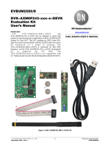
onsemi ADD5043-868-2-GEVK Operating instructions

Type
Operating instructions

The onsemi ADD5043-868-2-GEVK is a development kit that enables engineers and hobbyists to evaluate the capabilities of the ADD5043-868-2 transceiver module and to develop various wireless applications. It operates in the 868 MHz ISM band and provides a range of features, including a built-in antenna, an integrated power amplifier, a low-noise amplifier, and support for multiple modulation techniques. The kit comes with a comprehensive software package that includes configuration tools, sample code, and documentation, making it easy to get started with developing wireless solutions.

The onsemi ADD5043-868-2-GEVK is a development kit that enables engineers and hobbyists to evaluate the capabilities of the ADD5043-868-2 transceiver module and to develop various wireless applications. It operates in the 868 MHz ISM band and provides a range of features, including a built-in antenna, an integrated power amplifier, a low-noise amplifier, and support for multiple modulation techniques. The kit comes with a comprehensive software package that includes configuration tools, sample code, and documentation, making it easy to get started with developing wireless solutions.

QUICK START GUIDE
DVK-2
Version 2.0
Version 2.0
Quick Start Guide DVK-2
2/23
Table of Contents
1.
DVK-2 Introduction .....................................................................................3
1.1.
DVK-2 base-kit.............................................................................................3
1.2.
DVK-2 add-on-kits ........................................................................................3
2.
AXDBG Debug Adapter Overview................................................................5
3.
Main Board Overview (MB)..........................................................................6
4.
Batteries and Modules .................................................................................8
4.1.
Batteries......................................................................................................8
4.2.
Modules.......................................................................................................9
5.
Various Antennas ......................................................................................10
6.
Software required to work with the DVK-2................................................11
7.
Configuration of AxCode::Blocks................................................................12
8.
Connecting the DVK-2 to a PC....................................................................13
9.
Operation with AX-MicroLab......................................................................15
10.
Pre-installed PER-test ...............................................................................16
10.1.
Transmitter side ..................................................................................16
10.2.
Receiver side ......................................................................................17
11.
Working with AX-RadioLab........................................................................18
12.
Working with AxCode::Blocks....................................................................19
13.
Installation of Software.............................................................................20
14.
Different SW packages playing together....................................................21
15.
Glossary ....................................................................................................22
16.
Contact Information ..................................................................................23
Version 2.0
Quick Start Guide DVK-2
3/23
1. DVK-2 Introduction
1.1. DVK-2 base-kit
The DVK-2 is designed as quick start solution for the development of applications with
AXSEM micro-controllers and AXSEM radio-chips. The DVK-2 base-kit is the
development platform for applications based on the AX8052F1xx micro-controller
family. With the available radio add-on-kits it becomes the ideal platform for radio
performance evaluation and radio system development. The DVK-2 is compatible with
AX-RadioLab, AX-MicroLab and AxCode::Blocks development software for the PC.
The DVK-2 comes with:
2x mainboards with radio-module connectors for one radio add-on-kit module,
AX8052F100 20 MIPS ultra-low-power micro-controller, LCD display, 4 buttons,
2 LED, AX debug connector and battery connector for 3 AA batteries
1x AXDBG debug adapter
1x Mini USB cable
1x AX-Debug cable (Ethernet cable).
1.2. DVK-2 add-on-kits
For evaluation of AXSEM radio IC a variety of add-on-kits are available. A radio add-
on-kit consists of a pair of radio modules (and depending on region, frequency,
distributor a pair of antennas). Depending on the radio product the kit can consist of two
Version 2.0
Quick Start Guide DVK-2
4/23
identical or two different1 modules. The pictures below show the two different modules of
the AX5043-868 add-on-kit.
The left module has a TX/RX port and the right module a TX/RX port with SMA connector
and a single ended TX-only port without SMA connector.
The following radio add-on-kits are available:
AX5043-868 add-on-kit (2 modules)
AX5043-433 add-on-kit (2 modules)
AX5043-169 add-on-kit (2 modules)
AX5051-868 add-on-kit (2 modules)
AX5151-868 add-on-kit (2 modules)
AX5042-868 add-on-kit (2 modules)
For transmitter only evaluation the following transmitter modules are available
AX5031-868 module
AX5131-868 module
1 AX5043 add-on-kits are normally shipped with two different modules, a module with
an RX/TX RF port and a module with an RX/TX plus a TX-only port.
Version 2.0
Quick Start Guide DVK-2
5/23
2. AXDBG Debug Adapter Overview
The AXDBG debug adapter is the interface between the PC and the mainboards. It can
be used for programming and debugging the AX8052F1xx family of micro-controllers. It
interfaces on the computer side with low level drivers and the AXSDB software interface,
which is then used by other AXSEM software products. The AXSDB can also be used in
mass production with the scriptable AXSDB software.
The AXDBG has the following interfaces and indicators:
AX debug link RJ45 connector
mini USB PC interface
LED red indicating the debug link is active, MCU in debug mode
LED green indicating a program is executed on the MCU
Optional module connectors (not used by actual AXSEM software prducts)
Version 2.0
Quick Start Guide DVK-2
6/23
3. Main Board Overview (MB)
A DVK-2 mainboard is the core of the DVK-2 development system. It uses an
AX8052F100 as a versatile ultra-low-power micro-controller. The mainboard is designed
to evaluate AXSEM radio IC as well as being a platform for code development and
testing.
The DVK-2 mainboard is equipped with the following components:
1. LCD display with 2 lines of 16 characters each
2. Power indicator LED
1. 2.
6.
7.
3.
8.
9.
10.
5. 4. 11. 13. 12.
Version 2.0
Quick Start Guide DVK-2
7/23
3. DVK-2 radio module connectors
4. Programmable indicator LED
5. AX8052F100 micro-controller
6. AX debug link RJ45 connector
7. Power supply switch (select between debug link powered and battery powered
operation)
8. 4 dip switches
9. 4 power-supply jumpers:
a. Power for the LCD-display backlight
b. Power of the radio-module
c. Auxiliary power of the radio-module (TCXO, module recognition)
d. Power for the AX8052F100 micro-controller on the mainboard
10. 4 buttons
11. 32.768 kHz crystal
12. UART connect
13. GND test point
Version 2.0
Quick Start Guide DVK-2
8/23
4. Batteries and Modules
4.1. Batteries
Three AA batteries can be inserted on the bottom side of the DVK-2 mainboard. The
polarity is indicated on the picture below. The power switch toggles between battery
powered and debug-link powered operation. There is no OFF position if batteries are
inserted and the debug-link is connected.
+
+
-
Version 2.0
Quick Start Guide DVK-2
9/23
4.2. Modules
One radio module can be connected to the main board. The DVK-2 modules have to be
connected to the main board with the SMA connector facing outside.
Note: There is no safeguard for polarity or wrong insertion of modules.
Version 2.0
Quick Start Guide DVK-2
10/23
5. Various Antennas
Different types of antennas can be used with the AXSEM radio modules. The kits come
without antenna but any 50 Ohm antenna designed for a frequency matching the radio
module and being equipped with a male SMA connector can be used. Be aware that
antenna performance can vary a lot between different makes of antennas.
1 2 3 4 5 6 7
Antennas in the picture:
1. 868 MHz dipole (two grey rings, often used by AXSEM)
2. 915 MHz dipole (two yellow rings, often used by AXSEM)
3. 868 MHz monopole
4. 868 MHz monopole
5. 433 MHz monopole
6. 868 MHz monopole
7. 868 MHz monopole
Version 2.0
Quick Start Guide DVK-2
11/23
6. Software required to work with the DVK-2
Depending on your application and add-on-kit you need to use different AXSEM software.
Kit Matching Software
DVK-2 base-kit, no module attached AX8052IDE package
o AXCode::Blocks
o AXSDB
o LibMF
o SDCC
AX-MicroLab
DVK-2 base-kit with AX5043 add-on AX8052IDE package
o AXCode::Blocks
o AXSDB
o LibMF
o SDCC
AX-RadioLab
AX-RadioLab-POCSAG (not free of charge)
Pre-installed PER-test
DVK-2 base-kit with AX5051 add-on or AX5151 add-on AX8052IDE package
o AXCode::Blocks
o AXSDB
o LibMF
o SDCC
AX-RadioLab51
Pre-installed PER-test
DVK-2 base-kit with AX5042 add-on, AX5031 add-on
or AX5131-add-on
AX8052IDE package
o AXCode::Blocks
o AXSDB
o LibMF
o SDCC
AX-ParamCalc
AX-Easy_packet
Pre-installed PER-test
2
Note: AX-MicroLab and AX-RadioLAB use the AX8052IDE software package in the
background. Therefore the AX8052IDE software package has to be installed and
configured before installation of the other software. For configuration run
AxCode::Blocks and set SDCC as default compiler.
2 Note: AX5031 and AX5131 modules are transmitters only and do not work on
mainboards programmed as receiver
Version 2.0
Quick Start Guide DVK-2
12/23
7. Configuration of AxCode::Blocks
After starting AxCode::Blocks for the first time the user has to select SDCC as the
default compiler. The following window will pop-up. After this configuration process you
are ready to go.
Note:To delete an AxCode::Blocks configuration you have to delete the directory
C:\Documents and Settings\user\Application Data\axcodeblocks.
1.
2.
3.
Version 2.0
Quick Start Guide DVK-2
13/23
8. Connecting the DVK-2 to a PC
Step 1: To interface with the user the DVK-2 uses a suite of software on a PC.
AX8052IDE package (Installs AxCode::Blocks, AXSDB, LibMF support libraries,
the SDCC C-compiler and low-level drivers)
AX-RadioLab
AX-RadioLab51
AX-MicroLab
Make sure that the AX8052IDE software is installed before connecting the AXSDB to
the computer and before installing the other AXSEM software. Otherwise you may
experience difficulties in installing the driver later. AX-RadioLab, AX-RadioLab51 or
AX-MicroLab may be installed later, depending on the users intentions.
All necessary software can be downloaded at www.axsem.com .
Step 2: Connect the AXDBG via the USB cable to the computer. Since the driver is
already installed the computer should report 2 “USB Serial Converters” in your Device
Manager.
Step 3: Connect a DVK-2 mainboard via the blue RJ45 cable to the AXDBG debug
adapter.
Version 2.0
Quick Start Guide DVK-2
14/23
The base system is now ready for testing e.g. with AX-MicroLab for a start.
Note: If powered via the debug adapter the user can see voltage changes on
the mainboard if the current consumption changes. This is caused by a cascade
of two 3.3V regulators, on the AXSDB and on the mainboard. The effect is
visible in changes of the back light of the LCD display. It does not occur with
battery powered operation. This is fixed on the newest versions of the DVK-2.
Version 2.0
Quick Start Guide DVK-2
15/23
9. Operation with AX-MicroLab
AX-MicroLab is a great starting point for micro-controller code development with the
AX8052F1xx family of micro-controllers. It creates a framework of code for different
applications and helps to configure the functions of the micro-controller.
AX-MicroLab has a “DVK-2 Board” button (see arrow) to create a DVK-2 compatible
configuration quickly. For details look in the AX-MicroLab documentation, which is
available at www.axsem.com .
Version 2.0
Quick Start Guide DVK-2
16/23
10. Pre-installed PER-test
The DVK-2 mainboards come with a pre-installed software for tests with DVK-2 radio
add-on modules. The pre-installed software recognises most AXSEM radio add-on
modules and automatically starts testing packet error rate. One DVK-2 mainboard is
programmed with a transmitter the other with a receiver. Just plug in batteries, attach
radio modules and set the power supply switch to battery. For longer range use
antennas. The transmitter indicates the number of the last transmitted packet, while the
receiver indicates the packet error rate (PER), the RSSI and the frequency offset. Walk
around and check out for the great distance you can achieve.
Note: The SW does not accurately sense AX5043 modules for 433 and 169 MHz
and modules with 48 MHz TCXO. For those modules it is recommended to use
AX-RadioLab.
The pre-installed SW running on the main boards can be downloaded from the AXSEM
web-page www.axsem.com . Open slave.cbp in AxCode::blocks to download the
receiver and master.cbp to download the transmitter. The project main.cbp allows to
toggle between transmitter and receiver by pressing SW4 during power-up.
The radio parameters of this software cannot be changed. It is recommended to use AX-
RadioLab or AX-RadioLab51 for in depth testing. With AX5042 and AX5031 we
recommend AX-ParamCalc with AX-Easy_Packet as development and testing
platform.
10.1. Transmitter side
The transmitter sends a standard AXSEM HDLC packet every second.
The LCD display shows:
AXSEM RF: AX50xx
0051 (the last transmitted packet number)
Transmit parameter:
868.3 MHz
100 kbps
max power
FSK, deviation h=0.5
duty cycle ~1s
Version 2.0
Quick Start Guide DVK-2
17/23
10.2. Receiver side
The application on the AX8052F100 receives the data packets from the transmitter and
shows packet error rate, signal strength and frequency offset.
The LCD display shows:
P:0014 O:00397
L:0000 R: -034
P is the number of received packets
L is the number of lost packets
O is the frequency offset in Hz
R is the receiver strength indicator (RSSI) in dBm
Note: The receiver screen updates only if a valid packet was received.
Note: If the transmitter is reset during the test, the P and L values become
invalid.
Version 2.0
Quick Start Guide DVK-2
18/23
11. Working with AX-RadioLab
AX-RadioLab is the most advanced development tool for SRD radio applications. It
offers a variety of transmitter and receiver options such as
Periodic transmission of packets timed with the RC oscillator of the AX5043
Periodic transmission of packets timed with the 32 kHz XTAL oscillator of the MCU
Transmit on push-button
Wake-on-radio reception with programmable wake-up interval
Synchronous transmit and receive with programmable wake-up interval
Optional acknowledge package send for all modes
On top of this AX-RadioLab also allows to configure the packet format, as well as the
PHY.
Since AX-RadioLab is a source code generator the developer inherits the entire C-code
necessary to run his application. This makes radio code development quick and reliable.
AX-RadioLab also estimates the power consumption of the radio device. For most
modes the AX8052F100 power consumption is negligible. Average and peak currents
are indicated for transmitter and receiver.
Version 2.0
Quick Start Guide DVK-2
19/23
12. Working with AxCode::Blocks
AxCode::Blocks is the graphical IDE for code development on AXSEM micro-
controllers. It enables the developer to access all the degugging features of the AXSEM
micro-controllers, in particular:
Unlimited3 number of break points
Access to all AX8052F1xx MCU registers as well as to all AXSEM radio chip
registers
Debug link UART in a window for debugging printf-style without the need of extra
hardware
SDCC C-compiler pre-installed and ready to go
3 Limited only by memory size
Version 2.0
Quick Start Guide DVK-2
20/23
13. Installation of Software
Download AX8052-IDE-setup.exe.zip, AX-RadioLab.zip and AX-MicroLAB.zip from
www.axsem.com.
The AX8052-IDE-setup.exe.zip has to be unzipped and then comes as windows installer
executable, which needs administrator privileges to be executed. It installs the
AxCode::Blocks IDE, the SDCC C-compiler, the LibMF support libraries, the AXSDB
command line debugger and low level drivers. Check the support page of
www.axsem.com for tips and tricks and problem solving with the installation of the IDE,
especially in conjunction with 64-bit versions of operating systems.
The AX-RadioLab and AX-MicroLAB come as zip-file which have to be unzipped into a
temporary directory. Run setup.exe in that temporary directory. The temporary directory
can be deleted after installation.
Note: The installer requests reboots of the computer, which is not necessary.
Note: If you already have a version installed, the setup.exe first uninstalls the
existing version of the software. You have to run the installer a second time to
install then the software.
The default location for AX-RadioLab, AX-MicroLAB, AxCode::Blocks and AXSDB is in
the c:\program files\AXSEM directory. The SDCC C-compiler is typically installed directly
into the c:\program files directory. LibMF and the supporting libraries are installed in the
AXSDB directory.
Please check the respective documentations for details.
  • Page 1 1
  • Page 2 2
  • Page 3 3
  • Page 4 4
  • Page 5 5
  • Page 6 6
  • Page 7 7
  • Page 8 8
  • Page 9 9
  • Page 10 10
  • Page 11 11
  • Page 12 12
  • Page 13 13
  • Page 14 14
  • Page 15 15
  • Page 16 16
  • Page 17 17
  • Page 18 18
  • Page 19 19
  • Page 20 20
  • Page 21 21
  • Page 22 22
  • Page 23 23

onsemi ADD5043-868-2-GEVK Operating instructions

Type
Operating instructions

The onsemi ADD5043-868-2-GEVK is a development kit that enables engineers and hobbyists to evaluate the capabilities of the ADD5043-868-2 transceiver module and to develop various wireless applications. It operates in the 868 MHz ISM band and provides a range of features, including a built-in antenna, an integrated power amplifier, a low-noise amplifier, and support for multiple modulation techniques. The kit comes with a comprehensive software package that includes configuration tools, sample code, and documentation, making it easy to get started with developing wireless solutions.

Ask a question and I''ll find the answer in the document

Finding information in a document is now easier with AI