Page is loading ...

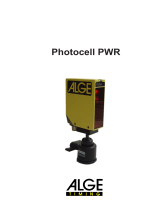
Photocell
Version-E16-06-02
Manual

Manual
PR1aW
Page 2
Important Information
General
Before using your ALGE-TIMING device read the complete manual carefully. It is part of the device and
contains important information about installation, safety and its intended use. This manual cannot cover
all conceivable applications. For further information or in case of problems that are mentioned not at all
or not sufficiently detailed, please contact your ALGE-TIMING representative. You can find contact details
on our homepage www.alge-timing.com
Safety
Apart from the information of this manual all general safety and accident prevention regulations of the
legislator must be taken into account.
The device must only be used by trained persons. The setting-up and installation must only be executed
according to the manufacturer’s data.
Intended Use
The device must only be used for its intended applications. Technical modifications and any misuse are
prohibited because of the risks involved! ALGE-TIMING is not liable for damages that are caused by im-
proper use or incorrect operation.
Cleaning
Please clean the outside of the device only with a smooth cloth. Detergents can cause damage. Never
submerge in water, never open or clean with wet cloth. The cleaning must not be carried out by hose or
high-pressure (risk of short circuits or other damage).
Liability Limitations
All technical information, data and information for installation and operation correspond to the latest
status at time of printing and are made in all conscience considering our past experience and knowledge.
Information, pictures and description do not entitle to base any claims. The manufacturer is not liable for
damage due to failure to observe the manual, improper use, incorrect repairs, technical modifications,
use of unauthorized spare parts. Translations are made in all conscience. We assume no liability for
translation mistakes, even if the translation is carried out by us or on our behalf.
Disposal
If a label is placed on the device showing a crossed out dustbin on wheels (see drawing),
the European directive 2002/96/EG applies for this device.
Please get informed about the applicable regulations for separate collection of electrical and
electronical waste in your country and do not dispose of the old devices as household
waste. Correct disposal of old equipment protects the environment and humans against
negative consequences!
Copyright by ALGE-TIMING GmbH
All rights reserved. Any duplication, either in full or in part, requires the prior written consent of the
copyright holder.

Manual
PR1aW
Page 3
Declaration of Conformity
We declare that the following products comply with the requirements of the listed standards.
We, ALGE-TIMING GmbH
Rotkreuzstrasse 39
A-6890 Lustenau
Declare under our sole responsibility, that the:
Photocell PR1aW
complies with the following standards/normative documents and in case of intended use com-
plies with the basic requirements of R&TTE 1999/5/EC:
Telecommunication (TC)terminal device
Short Range Device
Applied harmonized standards…
EN 60950-1: 2006 + A11:2009EMC:
EN300328 V1.71
EN 301489-1 V1.8.1 2008
EN 301489-3 V1.4.1 2002
EN55022:2006+A1:2007
EN55024:1998+A1:2001+A2:2003
EN61000 3-2:2006
EN61000 3-3:1995+A1:2001+A2:2005
Additional Information:
The product herewith complies with the requirements of the Low Voltage Directive 73/23/EEC,
also the EMC Directive 2004/108EG and accordingly carries the CE-marking.
Lustenau, 19.10.2012 ALGE-TIMING GmbH
Albert Vetter
(General Manager)

Manual
PR1aW
Page 4

Manual
PR1aW
Page 5
Contents
1 General ......................................................................................................................... 6
1.1 Functionality ......................................................................................................... 6
1.2 Photocell Features ................................................................................................ 6
1.3 Photocell Sets ....................................................................................................... 6
1.3.1 Reflection photocell PR1aW-R: ....................................................................................................... 7
1.3.2 Reflection photocell PR1aW-RT: ..................................................................................................... 7
1.3.3 One-way photocell PR1aW-dT: ....................................................................................................... 7
2 Operating Modes ......................................................................................................... 7
2.1 Reflection Photocell – NORM ............................................................................... 7
2.2 One-way Photocell ................................................................................................ 7
3 Power Supply .............................................................................................................. 8
3.1 External supply from ALGE timing devices ............................................................. 8
3.2 External Supply .................................................................................................... 8
3.3 Internal Battery ..................................................................................................... 8
3.3.1 Insert Batteries ................................................................................................................................. 9
3.3.2 Operating Time of Batteries ............................................................................................................. 9
4 LED-Operating Mode Indication ................................................................................. 9
5 Alignment of Photocell ............................................................................................. 10
5.1 Reflection Photocell ............................................................................................ 10
5.2 One-way Photocell .............................................................................................. 10
5.3 Setting of Delay Time ......................................................................................... 11
5.4 Synchronisation of two Photocells ...................................................................... 11
6 Weather protection .................................................................................................... 12
7 Radio Function .......................................................................................................... 13
7.1 Radio Power Output ........................................................................................... 14
7.2 Switching the Radio Module On or Off ................................................................ 14
7.3 Adjustment of Team Number .............................................................................. 14
7.4 Adjustment of Timing Channel ............................................................................ 15
7.5 LED for Radio ..................................................................................................... 15
8 Technical Data ........................................................................................................... 16
8.1 Photocell ............................................................................................................. 16
8.2 Built in Radio ...................................................................................................... 16

Manual
PR1aW
Page 6
General
The photocell PR1a combines highest precision and performance with smallest dimensions.
1.1 Functionality
The photocell transmitter sends a modulated light beam in infrared range. The receiver moni-
tors the light beam for disruptions. In case of a disruption of the infrared beam the receiver
releases a pulse. For multipurpose use the photocell can be operated in three different opera-
tion modes: reflection photocell, transmitter and receiver. The photocell can send the timing
impulse by cable or radio.
1.2 Photocell Features
• Releasing accuracy 1/10.000 second
• Diversity of types:
− Reflection photocell
− One-way photocell for large distances
• Large photocell range:
− Reflection photocell approx. 25 m
− Transmitter and receiver photocell more than 150 m
• Variable supply of the photocell:
− Battery operation
− Supply from ALGE timing device
− External supply from 4 to 18 VDC
• Battery condition indication with LED (green, yellow, red)
• Indication of the photocell alignment with LED (green, yellow, red)
• Indication for radio function
• Rotation switch to adjust the timing channel for radio use
• Rotation switch to adjust the radio frequency
• Synchronisation of two photocells (main and backup), to prevent interferences
• Setting of delay time (approx. 20 ms to 2 s /factory setting = 20 ms)
1.3 Photocell Sets
According to the photocell set it can consist of the following parts:
Photocell Reflector Mounting bracket Mounting bracket
PR1a PR1a-Ref BBG B-S1
Tripod TRI128 Photocell cable 001-10 Photocell cable 001-30

Manual
PR1aW
Page 7
Additional photocell accessory:
• Carrying case for photocell(s) and/or other accessory
• Two-core photocell cable with banana plug (different lengths)
• Cable reel with two-core steel cable with banana plug and/or banana socket
• Lengths: KT120 (120 m), KT150 (150 m), KT300 (300 m), KT500 (500 m)
• Charging set including 4 NiMH rechargeable batteries for photocell
• Reflector with centered screw hole (for mounting at wooden pole)
• Reflector with adhesive tape (for fixed reflector)
• Synchronisation cable for 2 photocells 163--5
1.3.1 Reflection photocell PR1aW-R:
In case transmitter and receiver are in one case, we refer to a reflection or two-way photocell.
The light beam is aimed from transmitter to a reflector. The reflector works like a mirror and
reflects the light beam to the receiver.
Range: approx. 25 m
Photocell set: 1 x PR1aW, 1 x PR1a-Ref, 2 x BBG, 1 x 001-10 (10m)
1.3.2 Reflection photocell PR1aW-RT:
Same as reflection photocell PR1aW-R, without mounting brackets BBG but with tripods and
30 m photocell cable.
Range: approx. 24 m
Photocell set: 1 x PR1aW, 1 x PR1a-Ref, 2 x TRI128, 1 x 001-30 (30 m)
1.3.3 One-way photocell PR1aW-dT:
Same as one-way photocell PR1aW-d, without mounting brackets BBG but with tripods and
30 m photocell cable.
Range: more than 150 m
Photocell set: 2 x PR1aW, 2 x TRI128, 1 x 001-30 (30 m)
2 Operating Modes
The photocell can be used in different operating modes.
• Reflection photocell
• Transmitter photocell TX
• Receiver photocell RX
2.1 Reflection Photocell – NORM
The reflection photocell PR1Wa sends from the transmitter an infrared light beam that is re-
flected by the reflector and analized by the receiver. The maximum range of the photocell is
25 m (distance between photocell and reflector).
This photocell requires the following parts:
• Photocell PR1Wa (Switch setting NORM)
• Reflector PR1a-Ref
2.2 One-way Photocell
For a working photocell set a transmitter PR1a (switch setting TX) and a receiver PR1aW
(switch setting RX – see below) is needed. The transmitter sends an infrared light beam to the
receiver. The maximum range is approx. 150 m. The receiver photocell must be the one with
integrated radio, since the receiver photocell will send the impulse to the timing device.

Manual
PR1aW
Page 8
3 Power Supply
The photocell can be supplied in different ways. The easiest supply is carried out
with the included cable 001-10 (or 001-30) directly from the ALGE timing device.
In radio mode the photocell must be supplied with batteries (2 x AA battery in
photocell).
Current consumption without battery: battery with 2,5 VDC: 20 - 46 mA
timing devices 5 Vstab: 9 - 20 mA
Current consumption with battery: battery with 2,5 VDC: 40 - 90 mA
timing devices 5 Vstab:18 - 40 mA
Connector pin assignment DIN socket:
1 ...... signal output
2 ...... signal output
3 ...... ground
4 ...... external supply (input 4 - 18 VDC)
5 ...... external supply (+5VDC stabilized – e.g. from ALGE timing devices)
3.1 External supply from
ALGE
timing devices
For a supply from the ALGE timing device use the photocell cable 001 (red) and/or 002 (green).
The ALGE timing device supplies a stabilized voltage of 5 VDC (pin 5).
ATTENTION:
The cable length is limited to approx. 100 m as otherwise the voltage drop would be too high.
3.2 External Supply
The photocell can be supplied by pin 4 (4 – 18 VDC) and pin 3 (ground). This is primarily of
advantage when several photocells have to be supplied by cable over large distance.
3.3 Internal Battery
The photocell can also be supplied by internal batteries (2 x AA battery).
The following types of batteries can be used:
Alkaline battery: Ideal in case the photocell is not used very often.
NiMH rechargeable batteries: Rechargeable batteries that is optimal in case the photo-
cell is used daily. These batteries have a long operating
time with very low temperatures.
NiCd rechargeable batteries: Not recommended for use in photocell.

Manual
PR1aW
Page 9
Switch on internal battery
The battery in the photocell is switched on with switch (on/off).
3.3.1 Insert Batteries
The battery cover is un-
derneath the photocell Press cover slightly inside
and pull forward Attention:
Mind the polarity of the
batteries! (sticker inside)
3.3.2 Operating Time of Batteries
The operating time of the photocell depends on different factors. Most importantly is what kind
of battery is used. The operating time becomes less with each additional photocell pulse. Also
important is whether the photocell is used as reflection photocell (transmitter and receiver)
and/or as transmitter or receiver.
-20°C 20°C -20°C 20°C
Alkaline Battery - 2,8 Ah apporx. 17 h apporx. 77 h apporx. 9 h apporx. 30 h
NiCd rechargeable - 1,1 Ah apporx. 11 h apporx. 28. h apporx. 6 h apporx. 14 h
NiMH rechargeable - 2,7 Ah apporx. 57 h apporx. 70 h apporx. 28 h apporx. 35 h
Battery Type
Photocell without Radio
Photocell with Radio
1 impulse per minute
1 impulse per minute
If the photocell PR1aW is used as a transmitter it almost has the same operating time as in
reflection photocell mode; for a receiver it is three times higher as for the reflection photocell.
4 LED-Operating Mode Indication
The LED of the photocell indicates several operating modes:
LED
Operating mode
NORM
Operating mode
RX
Operating mode
TX
permanently red Photocell misaligned
Photocell misaligned No indication
permanently yellow
Photocell not optimally
aligned
Photocell not optimally
aligend
No indication
permanently green
Photocell optimally
aligend
Photocell optimally
aligned
No indication
blinking red
Battery empty –
replace Battery empty –
replace
Battery empty –
replace
blinking yellow
Battery near empty
replace soon
Battery near empty –
replace soon
Battery near empty
replace soon
blinking green Battery full
Battery full Battery full

Manual
PR1aW
Page 10
5 Alignment of Photocell
5.1 Reflection Photocell
• If you use the photocell in the radio mode please check if you have full batteries in the
battery compartment.
• Adjust with rotation switch used Radio Team (same radio team as other network mem-
bers).
• Adjust with rotation switch the timing channel (e.g. start impulse = 0, finish impulse = 1).
• Screw mounting brackets BBG to wooden pole and/or position tripods TRI128
• Screw photocell and reflector on mounting brackets or tripods
• Align mirror of reflector straight to photocell
• Switch operating mode to <NORM>
• Switch on photocell:
− Batteries: Switch to <On>
− Supply from timing device: connect cable of timing device with photocell (red cable
001-xx or green cable 002-xx), switch on timing device
− External supply: connect external supply to photocell
• Operating mode LED must flash red
• Locate the reflector with the alignment notch
• Align the photocell until the operating mode LED flashes green
• After 5 seconds the operating mode LED has to blink green (indicates that the battery
and/or supply is okay). In case the LED blinks orange or red the battery should be re-
placed or the supply must be checked.
• After each photocell pulse the operating mode LED flashes green for several seconds
(indication for good photocell reception) before the battery condition is indicated again.
5.2 One-way Photocell
• If you use the photocell in the radio mode please check if you have full batteries in the
battery compartment.
• Photocell Receiver: Adjust with rotation switch used Radio Team (same radio team as
other network members).
• Photocell Receiver: Adjust with rotation switch the timing channel (e.g. start impulse = 0,
finish impulse = 1).
• Screw mounting brackets BBG to wooden pole and/or position tripods TRI128
• Screw photocells on mounting brackets or tripods
• Align photocells to each other
• Check if the operating mode is <NORM>. If not, switch to this position.
• Switch on photocells:
− Batteries: Switch to <On>
− Supply from timing device: connect cable of timing device with photocells (red ca-
ble 001-xx or green cable 002-xx), switch on timing device
− External supply: connect external supply to photocells
• Operating mode LED must flash red
• Locate the other photocell with the alignment notch
• Align the photocell until the operating mode LED flashes green
• After 5 seconds the operating mode LED has to blink green (indicates that the battery
and/or supply is okay). In case the LED blinks orange or red the battery should be re-
placed or the supply must be checked.
• Switch operating mode of transmitter photocell to TX - LED has to blink green, if supply
is okay.

Manual
PR1aW
Page 11
• Switch operating mode of receiver photocell to RX – LED works like the one of the reflec-
tion photocell.
• After each photocell pulse the operating mode LED of the receiver photocell flashes green
for several seconds (indication for good photocell reception) before the battery condition
is indicated again.
• Attention: The timing device has to be connected to the receiver photocell.
5.3 Setting of Delay Time
We recommend to set the delay time, if possible, at the timing device. At the factory, the delay
time of the photocell is set to the minimum which is 20 ms.
The delay time can be set with a screwdriver between 20 and 2000 ms. To reach it you have
to pull out the weather protection first.
Definition of delay time:
The delay time is the time during which the photocell is blocked after a photocell pulse. It starts
at that point when the light beam is no longer disrupted. This is necessary to prevent multiple
releases.
With this potentiometer the delay time can be set between 20 and 2000 ms
(Factory Setup = 20 ms)
5.4 Synchronisation of two Photocells
For using two photocells in parallel as system A and B, they should be synchronized. By syn-
chronization one photocell sets the cycle for the infrared pulses. By this it is guaranteed that
the photocells does not interfere each other. Connect cable 163--5 to both photocells. The LED
of the photocell that sets the synchronisation cycle flashes.

Manual
PR1aW
Page 12
6 Weather protection
The weather protection can be pulled out. With pulled out
weather protection the lenses are protected from snow and rain.
If the photocell is used on a glacier it is essential to pull out the
weather protection. Otherwise the increased UV radiation can
cause interferences.
Attention:
Direct solar radiation through the lense into the photocell has to
be prevented by all means. Direct solar radiation through the
lense can damage the photocell (burning glass effect).
Pull out weather protection

Manual
PR1aW
Page 13
7 Radio Function
The ALGE Wireless Timing Network WTN is a compact radio system for timing and is equipped
with the most updated technology. The photocell PR1aW has a WTN-radio module built in and
is fully compatible with other devices of the WTN-family.
A radio network consists of two or more devices of the WTN series. In such a network every
device communicates with every other device inside the network.

Manual
PR1aW
Page 14
The network is designed in such a way that you can transmit data to a display board (e.g.
ALGE GAZ or D-LINE), serial RS232 data (e.g. to a PC) and timing impulses at the same time.
When designing the Wireless Timing Network the ALGE development team concentrated on
features that make ALGE devices unique, but also on features that stand for ALGE products:
easy operation, highest reliability, rugged casing. Up-to-date technology, integrated in a solid
case, results in exceptional features.
Attention: Before using the device make sure that you are allowed to operate it in your country.
The radio power output must be adjusted so that it is legal to use it in the country you operate
it in.
The quality of the network status for a WTN system is crucial. Before you start to use the WTN
network check the connection quality of every WTN device used in the system. In order to work
in a stable network every WTN should show at least a good connection quality (the radio indi-
cation of the PR1aW should blink green).
7.1 Radio Power Output
The radio power output is adjusted to 10 mW. It can be adjusted between 10 mW and 100
mW. It is not possible to change the power output direct in the photocell. If you adjust the power
output in another device of the network (e.g. Wireless Timing Network WTN), than it will set all
devices in this network to the new adjusted power output (also as well the photocell PR1aW).
7.2 Switching the Radio Module On or Off
If you have the rotation switch on zero the radio is off. If you select other positions the radio is
on and you have selected a certain team number (frequency). Turn the radio here on
7.3 Adjustment of Team Number
This function is to select the team number of a WTN system. You can select between 15 team
numbers. There are 9 single teams (S) and 6 common teams (A). The factory setting is 1
(single mode). Adjust the team number her
Separate Teams <S> = SINGLE
Used for completely independent networks. If you operate two networks next to each other

Manual
PR1aW
Page 15
both networks work in this mode on different frequencies and do not communicate among each
other.
Single = rotation switch 1, 2, 3, 4, 5, 6, 7, 8 and 9
Joint Teams <A> = ALL
Used for networks that work independently next to each other. If different A teams with the
same radio channel are operated, the other A teams can be used for data transmission. The
data of the other team however is not used (e.g. for two show jumping grounds that are next
to each other).
All = rotation switch A, B, C, D, E and F
7.4 Adjustment of Timing Channel
For timing you can choose between 5 adjustable timing channels that are transmitted to the
receiver. The factory setting: C1
Selection: C0, C1, C2, C3 or C4 Adjust the timing channel here
For ALGE-TIMING the following timing channels are used:
0 = C0 = Start Channel
1 = C1 = Finish Channel
2 = C2 = Intermediate Time 1
3 = C3 = Intermediate Time 2 or Start Channel 2
4 = C4 = Intermediate Time 3 or Finish Channel 2
7.5 LED for Radio
The LED for the radio shows the communication status
with other devices in the same network (device with
the best reception).
LED status Function
off radio off or on network
red blinking very bad network reception
orange blinking bad network reception
green blinking good network reception

Manual
PR1aW
Page 16
8 Technical Data
8.1 Photocell
Range with reflector: 0.5 to 25 meter
Range with transmitter and receiver: 0 to over 150 meter
Pulse output: NPN Transistor, Open Collector, active low
Maximum output load: max. 250mW
max. 14V
max. 100mA
Reaction time: 300 µs, 1 ms set permanently
Pulse length: 20 bis 2000 ms adjustable (dead time)
Dimensions (without ball joint): approx. 118 x 87 x 44 mm
Weight PR1aW: approx. 0.3 kg
Weight PR1a-Ref: approx. 0.2 kg
Switch: On/Off switch for battery
Selector switch: for Norm, TX and RX
Power supply: from ALGE timing device: 5 VDC stabilized
external supply: 4 - 18 VDC
internal battery: 2 x AA batteries
Power consumption without radio: battery with 2.5 VDC: 20 - 46 mA
timing device with 5 Vstab: 9 - 20 mA
Power consumption with radio: battery with 2.5 VDC: 40 - 90 mA
timing device with 5 Vstab: 18 - 40 mA
Connector pin assignment DIN socket:
1 ...... signal output
2 ...... signal output
3 ...... ground
4 ...... external supply (input 4 - 18 VDC)
5 ...... external supply (+5VDC stabilized – e.g. from ALGE timing devices)
8.2 Built in Radio
Frequency: 2.4 GHz band (16 adjustable frequencies)
Power Output: 10 mW or 10 to100 mW (adjustable)
Timing Channels: 5 different timing channels (c0 (start), c1 (finish), c2, c3, c4)
Maximum Distance: about 300 m at free sight
Subject to changes
Copyright by
ALGE-TIMING GmbH
Rotkreuzstr. 39
6890 Lustenau / Austria
www.alge-timing.com
/


